Mega Machine BS-450HAS User manual

Automatic BANDSAWS
BS-450HAS
Full Stroke
INSTRUCTION MANUAL
MEGA MACHINE CO., LTD.
DOC NO:BS450HAS 全行程-100.U
CTRL NO:06
UPDATE:2009/6/17
DOC VER:A1

FOREWORD
We hope that the owner of this automatic circular sawing machine will
have years of trouble-free service. The machine has been built
to the highest standards to enable fast accurate cutting to be obtained.
In order that the best results can be achieved from your MEGA circular sawing
Machine, we would ask all operators and maintenance engineers to READ
THIS MANUAL CAREFULLY BEFORE STARTING THE MACHINE.
The manual contains full instructions on installation, operation, lubrication,
maintenance and trouble-shooting.
As MEGA MACHINE COMPANY LIMITED is constantly improving the
design of its machines, there may be some instance where this book differs
somewhat from the machine with which you are concerned. So, always
quote the Serial Number of your machine, when ordering spare parts
or in correspondence relating to the machine.
MODEL : BS450HAS
Serial Number :
Request for service and spare parts should be made to:
ADDRESS: NO. 180, INDUSTRIAL ROAD, TAI-PING CITY, 41107 TAICHUNG,
TAIWAN R. O. C.
URL: www.bandsaw.com.tw
TEL: 886 4 22712877(PRES.) FAX:886 4 22715016

TABLE OF CONTENTS
Item Unit Page
1 Introductory Illustrations 1-1
1.1 Principal parts 1-1
2 Specifications 2-1
2.1 Specifications 2-1
2.2 Standard Accessories 2-1
3 Installation 3-1
3.1 Moving and lifting 3-1
3.2 Foundation layout and Set-up 3-2
3.2.1 Foundation 3-2
3.2.2 Leveling 3-3
3.2.3 Cleaning and oiling 3-3
3.2.4 Power Source Connection 3-4
4 Operation
4.1 Control Panel 4-1
4.2 Operating preparation 4-3
4.3 Manual Operation 4-4
4.4 Automatic operation 4-5
4.5 Special Operation 4-5
4.6 Break -In Operation 4-6
Addition 1 Amplifying Valve 4-7
5 Maintenance 5-1
5.1 Hydraulic Circuit 5-1
5.2 Oiling and Lubrication 5-2
5.3 Others 5-3
6 Trouble Shooting Guide
6.1 Sawing Problems and Solution 6-1
6.2 Minor Operating Troubles and Remedies 6-2
6.3 Error information 6-2
7 Reference Charts
7.1 Standard cutting Chart 7-1
7.2 Standard cutting Chart 7-2
7.3 Standard cutting Chart 7-3
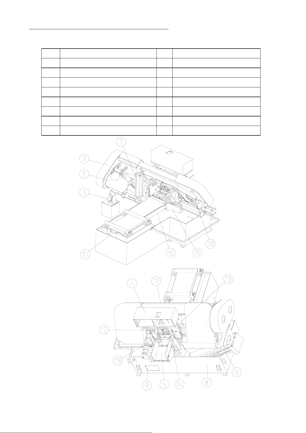
1. INTRODUCTORY ILLUSTRATIONS
1.1 Principal Parts
1 Coolant Pump 10 Hydraulic Blade Tension Set
2 Main Motor 11 Saw Frame
3 Pulley Cover 12 Guide Arm
4 Electric Control Box 13 Guide Arms Slide
5 Stock Tray 14 Quick Approach Rod
6 Chip Conveyance 15 Feed Assembly
7 Lift Cylinder 16 Slide Shaft
8 Water Trough 17 Feed Cylinder
9 Oil Tank 18 Vise
1 - 1
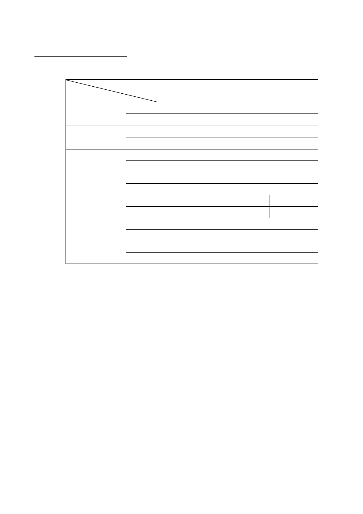
2 SPECIFICATIONS
2.1 SPECIFICATIONS
MODEL
SPECIFICATIONS BS-450HAS
(Mm) φ460 □460W*407H
Cutting Capacity (In) φ18” □18”*16”H
(Mm) 360W*255H
Bundle Cutting (In) 14“W*10”H
(Mm) 38W*1.3t *4880L
Blade Size (In) 1 1/2”W *0.05”t *192”L
(M/Min) 25,32,42,55,70,80 OPTIONAL 20 – 80
Blade Speed (F/Min) 82,105,138,180,230,260 OPTIONAL 65 – 260
(KW) Blade-5.6 HYD-1.5 Coolant-0.09
Motor Output (HP) Blade-7.5 HYD-2 Coolant- 1/8
(Mm) 2682L*2255W*1980H
Shipping Volume (Ft) 8.8L*7.4W*6.5H
KG 3100 / 3500
Weight Net/Gross Lb 6820 / 7700
Specifications subject to change without notice for improvement and modification.
2.2 STANDARD ACCESSORIES
1. Tools with tool box .............………….……..……....... 1 set
2. 7 ft.(2M) long roller table ...…………………..…......... 1 set
3. Band-cleaning wire brush ...…………………..….......... 1 pieces
4. Band saw blade .................…………………..……....... 1 piece
5. Instruction manual .............………………….……........ 1 copy
2 - 1
Table of contents
Other Mega Machine Saw manuals


