megapixel HELIOS User manual

HELIOS®
LED Processing Platform
Quickstart Guide
HELIOS v.21.05.0
May 7, 2021

HELIOS LED Processing Platform - Quickstart GUIDE i
For complete warranty and legal information please see the full HELIOS User Guide.
Legal
Copyright © Megapixel Visual Reality®.
The Megapixel VR®logo is a trademark of H2VR HoldCo, Inc. Other trademarks and trade names
may be used in this document to refer to products by other entities. Megapixel VR claims no
proprietary interest in trademarks and trade names owned by others.
Information and specications in this document are subject to change without notice. Megapixel VR
assumes no responsibility or liability for any errors or inaccuracies that may appear in this manual.
Contact
+1 818 884 5488
http://megapixelvr.com
support@megapixelvr.com
Warranty Information
Megapixel VR warrants the HELIOS Processing System, hardware products, against defects in
materials and workmanship under normal use for a period of one (1) year from the date of retail
purchase by the original end-user purchaser.
Megapixel VR does not warrant that the operation of the product will be uninterrupted or error free.
Megapixel VR is not responsible for damage arising from failure to follow product or installation
instructions.
Installation Environment
The HELIOS Processor is designed to be rack mounted in a central control room for xed
installations or ight cased for touring applications.
The unit has been qualied to operate in a dry environment within a temperature range of 10°C to
35°C (50°F to 95°F).
Certications
NOTE: Never obstruct the airow to the front/rear ventilation slots. The front lters need to be regularly
checked and cleaned.
5015417
Megapixel VR


HELIOS LED Processing Platform - Quickstart GUIDE 1
1
Power
2
Data
LAN
100-240VAC, 50/60 Hz, 3.8A In Out
13
2 4
13
2 4
5
6
7
8
Sync
Display Port HDMI
max. 250v~
1. Plug in (IEC to Edison cable included).
2. Switch ON.
Connect to the processor via the system control LAN. This can be done directly with a
laptop or for larger systems, with a wireless router.
LAN
100-240VAC, 50/60 Hz, 3.8A In Out
13
2 4
13
2 4
5
6
7
8
Sync
Display Port HDMI
max. 250v~

HELIOS LED Processing Platform - Quickstart GUIDE 2
3
WebUI
4
Login
1. Note the IP address of HELIOS on the front panel.
2. The HELIOS user interface is accessed with a modern web browser such as Chrome or
Safari. The computer running Chrome or Safari must be congured to be on the same
LAN as the HELIOS Processor. The IP address of the processor is reported on the front
display. Type the HELIOS IP into the search eld of a Chrome or Safari browser.
If security has been enabled, a login window will be shown. If the credentials are not
known, the HELIOS unit will need to be restored to factory defaults. Please see the full
HELIOS user guide appendix for more information about the factory defaults reset.
HELIOS LED Processing Platform - Quickstart GUIDE 3
5
Mapping
1. Physically connect the tiles with network cables in a repeating pattern. Often systems
connect tiles in columns left right / top down (viewed from the front of the display).
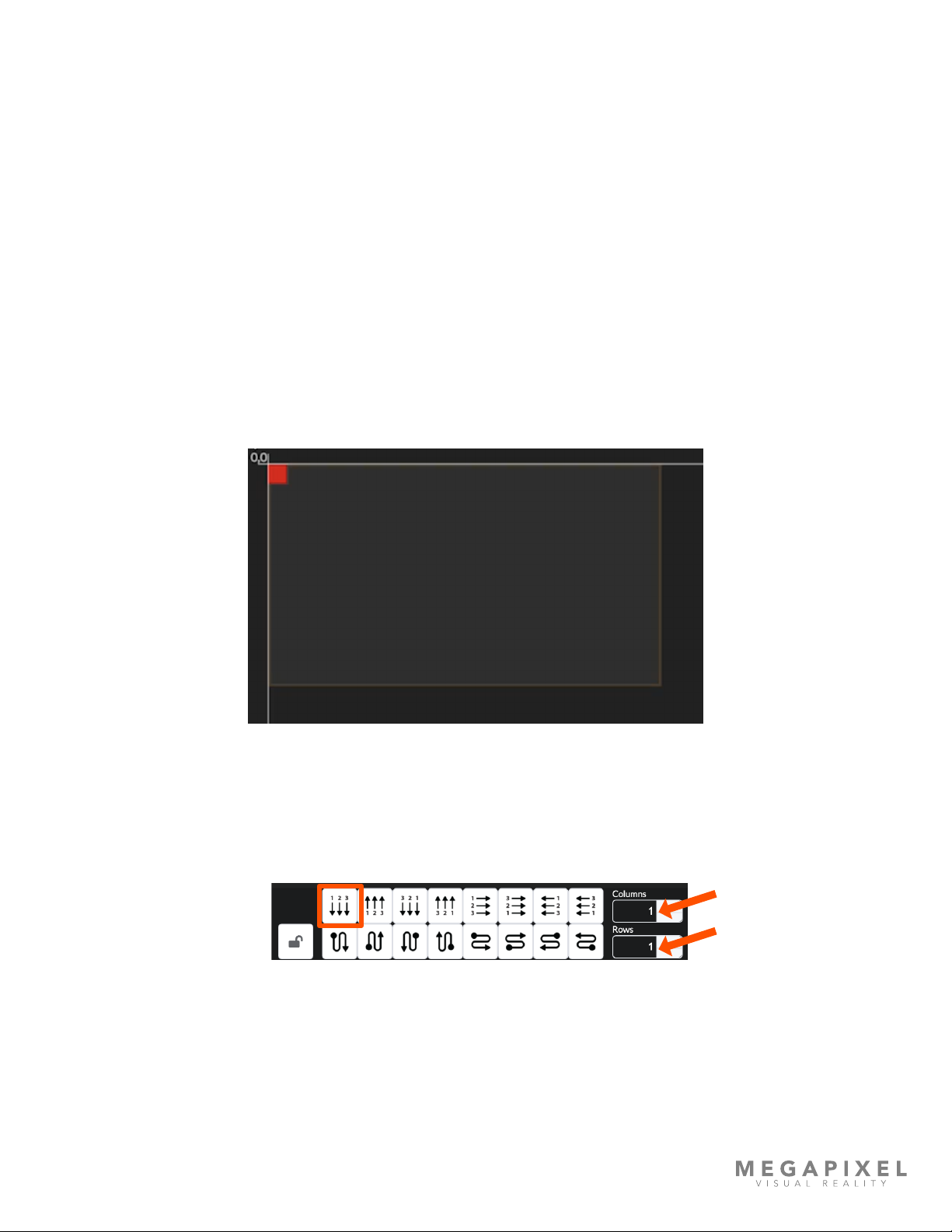
2. HELIOS will automatically recognize connected tiles and stack all tiles on top of each
other at the 0,0 position on the map. This helps get an image on all tiles, but it will be
the same duplicate image.
3. Select the stack of tiles at the (0,0) position, then select the cable topology from the
available icon buttons that represents the topology that was used to connect the tiles.
The left right / top down option is the rst one (highlighted).
4. To the right of the cable topology buttons (arrows above), enter the tile dimensions of
the display in columns and rows.


HELIOS LED Processing Platform - Quickstart GUIDE 5
7
Test Patterns
HELIOS systems can display two types of test patterns:
• Tile test patterns - recalled from the onboard memory of tiles.
• Video patterns - recalled from the onboard memory of HELIOS.
Tile test patterns are found on the Mapping pane under the Tile conguration accordion.


HELIOS LED Processing Platform - Quickstart GUIDE 7
8
HELIOS Indicators
HELIOS units have several small LED indicators on the rear of the units. Below are tables explaining
what each means.
VFMC Cards - Next to each VFMC video input connector is a small LED that indicates the status of
each VFMC input link.
Indicator Color Meaning
White System boot
Black No link (no cable)
Yellow Valid link, no video
Blue Valid link, valid video
Red Error detected in the last 1.25 sec
Green / Cyan / Magenta Training cycle
LAN
100-240VAC, 50/60 Hz, 3.8A In Out
13
2 4
13
2 4
5
6
7
8
Sync
Display Port HDMI
max. 250v~
HELIOS LED Processing Platform - Quickstart GUIDE 8
HELIOS Indicators (continued)
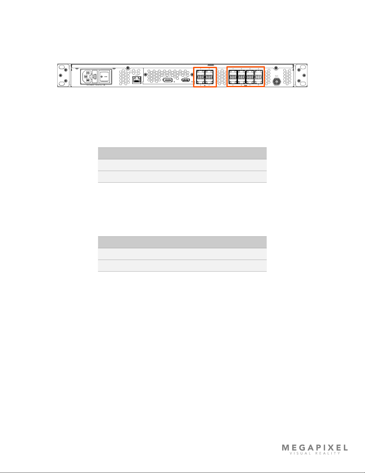
SFP+ I/O
SFP+ Inputs - Four (4) SFP+ slots provide copper SDI inputs. Each input requires a Megapixel 12G
SFP+ and supports formats up to 12G SDI. Indicators on each SFP+ show the status of the input.
SFP+ Outputs - HELIOS Standard units support up to eight Megapixel 10G ber SFP+ outputs for
data transmission to the display. Likewise, HELIOS Junior units support up to eight Megapixel 1G
copper SFP outputs. Indicators on each SFP+ slot show link status.
SFP+ Inputs SFP+ Outputs
LAN
100-240VAC, 50/60 Hz, 3.8A In Out
13
2 4
13
2 4
5
6
7
8
Sync
Display Port HDMI
max. 250v~
Indicator Color Meaning
Green Receiving a carrier signal
Blue Valid frame detected
Indicator Color Meaning
Green Link to switch
Blue Connected to tiles
HELIOS LED Processing Platform - Quickstart GUIDE 9
9
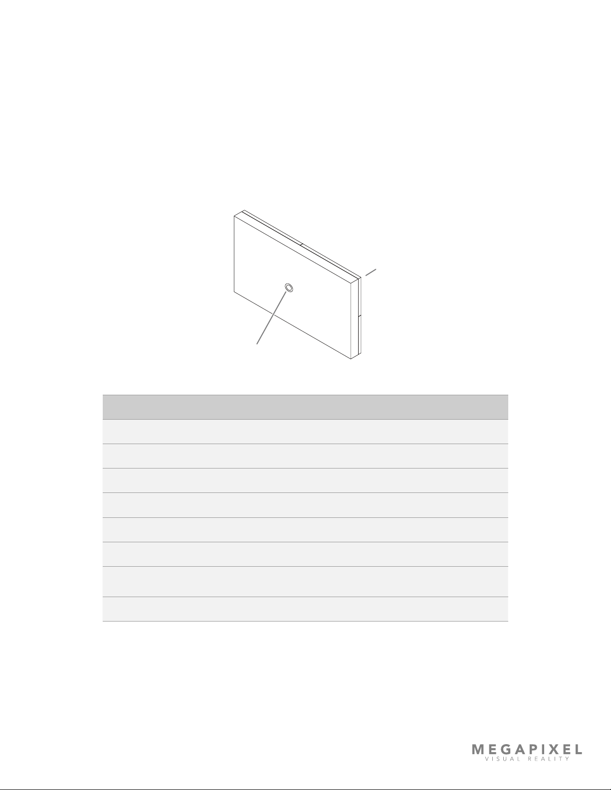
Display Tile Indicators
On the rear of each display tile is a multi color indicator button, the exact location varies by tile type.
The table below details the meaning of each of the colors and the function of the button.
Front
Status Indicator
Indicator Color Meaning
White Booting
Cyan Booted into safe mode
Green Ready (No network connection)
Blue Single Flash No HELIOS connection (1 tile link active)
Blue Double Flash No HELIOS connection (2 tile links active)
Blue Solid Connected to HELIOS (Normal operation)
Yellow Internal Pattern (press and hold center button 4 seconds to enter and
leave this mode). Press and release to advance to the next pattern.
Red Flash once every 10 sec to indicate a system error.
Other manuals for HELIOS
2
Table of contents


