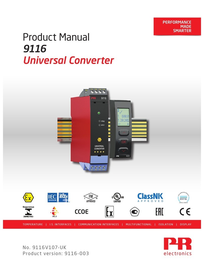
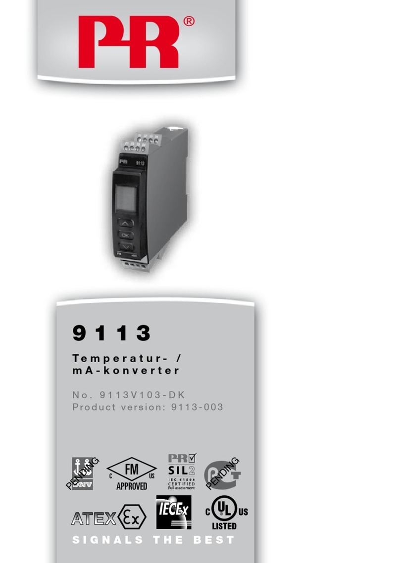
PR 9116 Series User manual

9116
Universal
converter
No. 9116V104-UK
Product version: 9116-003

1341
PR electronics A/S tilbyder et bredt program af analoge og digitale
signalbehandlingsmoduler til industriel automation. Programmet
består af Isolatorer, Displays, Ex-barrierer, Temperaturtransmittere,
Universaltransmittere mfl. Vi har modulerne, du kan stole på i selv
barske miljøer med elektrisk støj, vibrationer og temperaturudsving,
og alle produkter opfylder de strengeste internationale standarder.
Vores motto »Signals the Best« er indbegrebet af denne filosofi – og
din garanti for kvalitet.
PR electronics A/S oers a wide range of analogue and digital
signal conditioning devices for industrial automation. The product
range includes Isolators, Displays, Ex Interfaces, Temperature
Transmitters, and Universal Devices. You can trust our products in
the most extreme environments with electrical noise, vibrations and
temperature fluctuations, and all products comply with the most
exacting international standards. »Signals the Best« is the epitome
of our philosophy – and your guarantee for quality.
PR electronics A/S ore une large gamme de produits pour le
traitement des signaux analogiques et numériques dans tous
les domaines industriels. La gamme de produits s’étend des
transmetteurs de température aux acheurs, des isolateurs aux
interfaces SI, jusqu’aux modules universels. Vous pouvez compter
sur nos produits même dans les conditions d’utilisation sévères,
p.ex. bruit électrique, vibrations et fluctuations de température.
Tous nos produits sont conformes aux normes internationales les
plus strictes. Notre devise »SIGNALS the BEST« c’est notre ligne
de conduite - et pour vous l’assurance de la meilleure qualité.
PR electronics A/S verfügt über ein breites Produktprogramm an
analogen und digitalen Signalverarbeitungsmodule für die in-
dustrielle Automatisierung. Dieses Programm umfasst Displays,
Temperaturtransmitter, Ex- und galvanische Signaltrenner, und
Universalgeräte. Sie können unsere Geräte auch unter extremen
Einsatzbedingungen wie elektrisches Rauschen, Erschütterungen
und Temperaturschwingungen vertrauen, und alle Produkte von
PR electronics werden in Übereinstimmung mit den strengsten
internationalen Normen produziert. »Signals the Best« ist Ihre
Garantie für Qualität!
DK
UK
FR
DE

9116 - Product Version 9116-003 1
UNIVERSAL CONVERTER
9116
CONTENTS
Warning....................................................................................................... 2
Safety instructions................................................................................. 2
How to demount system 9000 ........................................................ 4
Advanced features................................................................................. 5
Application................................................................................................. 5
Technical characteristics...................................................................... 5
Applications............................................................................................... 6
PR 4501 Display / programming front........................................... 7
Ordering codes for 9116B .................................................................. 8
Accessories ............................................................................................... 8
Electrical specifications........................................................................ 8
Configuration of sensor error check................................................ 12
Input signal outside range.............................................................. 13
Sensor error detection...................................................................... 13
Hardware error..................................................................................... 14
Connections .............................................................................................. 16
Block diagram........................................................................................... 17
Signal error and cable fault indications
without display front......................................................................... 18
Configuration / operating the function keys............................... 19
Routing diagram...................................................................................... 24
Routing diagram, Advanced settings (ADV.SET)........................ 26
Scrolling help texts in display line 3............................................... 27
Graphic depiction of window ............................................................. 29
Graphic depiction of setpoint ............................................................ 30
Appendix.................................................................................................... 31
IECEx Installation Drawing.................................................................. 32
ATEX Installation Drawing .................................................................. 36
FM Installation Drawing....................................................................... 40
INMETRO Installation Drawing.......................................................... 44
Safety Manual .......................................................................................... 48

2 9116 - Product Version 9116-003
SYMBOL IDENTIFICATION
Triangle with an exclamation mark: Read the manual before installation
and commissioning of the device in order to avoid incidents that could lead
to personal injury or mechanical damage.
The CE mark proves the compliance of the device with the essential
requirements of the directives.
The double insulation symbol shows that the device is protected by
double or reinforced insulation.
Ex devices have been approved according to the ATEX directive for use in
connection with installations in explosive areas. See installation drawings
in appendix.
SAFETY INSTRUCTIONS
DEFINITIONS
Hazardous voltages have been defined as the ranges: 75...1500 Volt DC, and
50...1000 Volt AC.
Technicians are qualified persons educated or trained to mount, operate, and also
troubleshoot technically correct and in accordance with safety regulations.
Operators, being familiar with the contents of this manual, adjust and operate
the knobs or potentiometers during normal operation.
WARNING
The following operations should only be carried out on a discon-
nected device and under ESD-safe conditions:
General mounting, connection and disconnection of wires.
Troubleshooting the device.
Repair of the device and replacement of circuit breakers must
be done by PR electronics A/S only.
WARNING
Do not open the front plate of the device as this will cause dama-
ge to the connector for the display / programming front PR 4501.
This device contains no DIP-switches or jumpers.

9116 - Product Version 9116-003 3
RECEIPT AND UNPACKING
Unpack the device without damaging it and check whether the device type
corresponds to the one ordered. The packing should always follow the device
until this has been permanently mounted.
ENVIRONMENT
Avoid direct sunlight, dust, high temperatures, mechanical vibrations and shock,
as well as rain and heavy moisture. If necessary, heating in excess of the stated
limits for ambient temperatures should be avoided by way of ventilation.
The device must be installed in pollution degree 2 or better.
The device is designed to be safe at least under an altitude up to 2 000 m.
MOUNTING
Only technicians who are familiar with the technical terms, warnings, and instruc-
tions in the manual and who are able to follow these should connect the device.
Should there be any doubt as to the correct handling of the device, please contact
your local distributor or, alternatively,
PR electronics A/S
www.prelectronics.com
The use of stranded wires is not permitted for mains wiring except when wires
are fitted with cable ends.
Descriptions of input / output and supply connections are shown in the block
diagram and on the side label.
The device is provided with field wiring terminals and shall be supplied from
a Power Supply having double / reinforced insulation. A power switch shall be
easily accessible and close to the device. The power switch shall be marked as
the disconnecting unit for the device.
For installation on Power Rail 9400 the power is supplied by Power Control Unit
9410.
Year of manufacture can be taken from the first two digits in the serial number.
CALIBRATION AND ADJUSTMENT
During calibration and adjustment, the measuring and connection of external
voltages must be carried out according to the specifications of this manual. The
technician must use tools and instruments that are safe to use.
Other manuals for 9116 Series
2
Table of contents
Other PR Media Converter manuals
Popular Media Converter manuals by other brands

H&B
H&B TX-100 Installation and instruction manual

Bolin Technology
Bolin Technology D Series user manual

IFM Electronic
IFM Electronic Efector 400 RN30 Series Device manual

GRASS VALLEY
GRASS VALLEY KUDOSPRO ULC2000 user manual

Linear Technology
Linear Technology DC1523A Demo Manual

Lika
Lika ROTAPULS I28 Series quick start guide

Weidmuller
Weidmuller IE-MC-VL Series Hardware installation guide

Optical Systems Design
Optical Systems Design OSD2139 Series Operator's manual

Tema Telecomunicazioni
Tema Telecomunicazioni AD615/S product manual

KTI Networks
KTI Networks KGC-352 Series installation guide

Gira
Gira 0588 Series operating instructions

Lika
Lika SFA-5000-FD user guide
