MegaSquirt 2Extra User manual

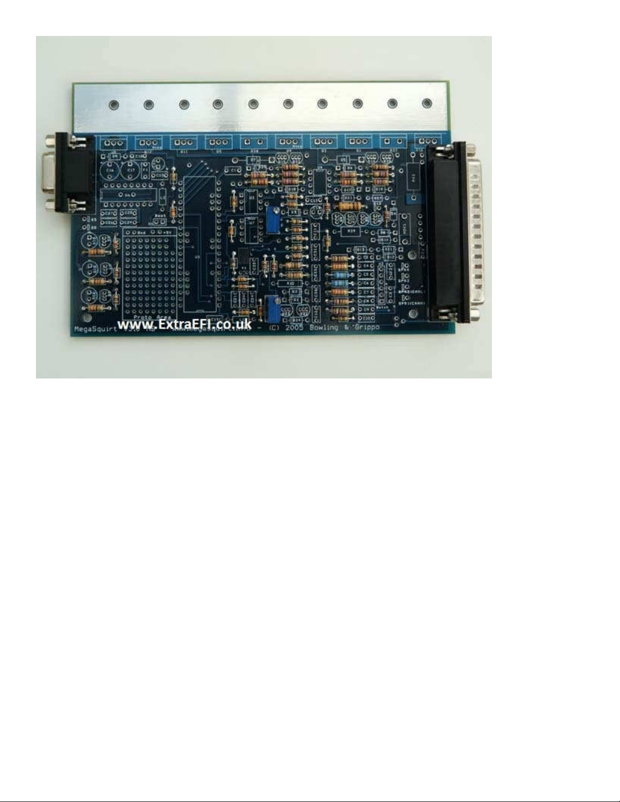
Megasquirt 2Extra (V3 board), 1997 Parallel Installation
Safety instruction from MS2 build manual (http://www.megamanual.com/ms2/V3assemble.htm):
Use an Ohmmeter (digital multi-meter set on resistance) to check the resistance between the three voltage
regulator holes. The voltage regulator is U5, near the DB9 connector in the top left side of the board (on the
heat sink). The resistance between any two of these three holes should be infinite. If it is not, contact the
supplier you bought the kit from. (This test ensures that the 12 Volt supply, 5 Volt internal supply, and ground
are not shorted together.)
MS2 Extra build instructions (http://www.msextra.com/doc/ms2extra/build_manual.htm)
3) Start the build by soldering in the 2 connectors (37pinned and 9 pinned items)
4) Next get all the bags of resistors together, keeping them in the bags. (R1, etc)
Find R12, R37, R38, R43, R39 and R57. Put them out of the way, you don’t need any of them, but R43 may
come in handy later. Solder the holes on the board for R39 so you don't accidentally fit it. (The rest will be fine
as you shouldn't find these in the parts to fit if you've put them to one side)
Note from JBPerf.com: If using the external injectors, remove
R21, R22,R23.
BM Note: If it’s a parallel install, don’t install R4 and R7 or the Coolant and Intake temp signals will be
incorrect for the stock ECU. Removing these means these inputs won’t work if you’re running on a
Stimulator.
5) Now solder all of the rest of the resistors in place. Note: There is no polarity for resistors, so they can fit in
either way round.
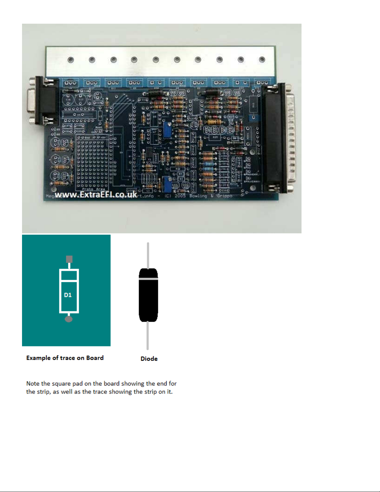
6) Next get all the bags of diodes together, keeping them in the bags. (D1, etc) Note, ALL of the diodes have a
strip on them that MUST go the same side as the strip marked on the board!
7) Remove D1 and D2 from the bags and put them to one side. Keep both these diodes as you may need them
(FIdle output mods). Note, D1 may need installing if your using a coil -ve triggering setup.
8) Now solder the 4 holes up on the main board for D1 and D2, so you don’t accidentally add them.
9) Find D8 and remove it from the bag. (Keep this to one side as you may need it later, it's a 22V Zener)
10) Now solder up the holes for D8 on the main board.
11) Next you can fit all the rest of the diodes (BM note: including the LED’s!)
12) Next get all the bags of capacitors together, keeping them in the bags (C1, etc).
If you’re using the coil –ve as the trigger input go to step 15 (This is rare now)
13) As long as you’re NOT using the coil –ve as the trigger input (Fuel only) find C30 and put it out of the way.
14) Solder the 2 holes up on the main board for C30 so you can’t fit a capacitor into the holes by accident.
Note from JBPerf.com: If using the external injectors, remove
C20,C21,C24,C25.
15) Find C22 and C14, C16 and C17. Solder these in. Note, these are polarised, ensure the lead with the “+”

next to it on the component goes into the square pad on the board, this is also labelled with a ”+” on the board.
16) Now solder all the rest of the capacitors in.
16B) Solder in the two polyfuses F1 and F2. Solder in the two inductors L1 and L2, leave a little gap
underneath. Solder in MOV1 (looks like a big round capacitor.) (Not shown installed in this photo.)
17) Now find the bag with all the chips in it, U6, U3, U7 and U4. Solder these in place, be careful to get them
the correct way round!
Note, the notch in the component must line up with the notch shown on the board. All notches face the top of the
board, U6 notch to the left.
18) Find Q16, (Ignition Transistor), D14, D15 and D16 (LEDs) Q4 and Q20 (small transistors) and U1 (black
40 pinned chip for MS1 or small daughter board for MS2) put these to one side, don’t lose them!!
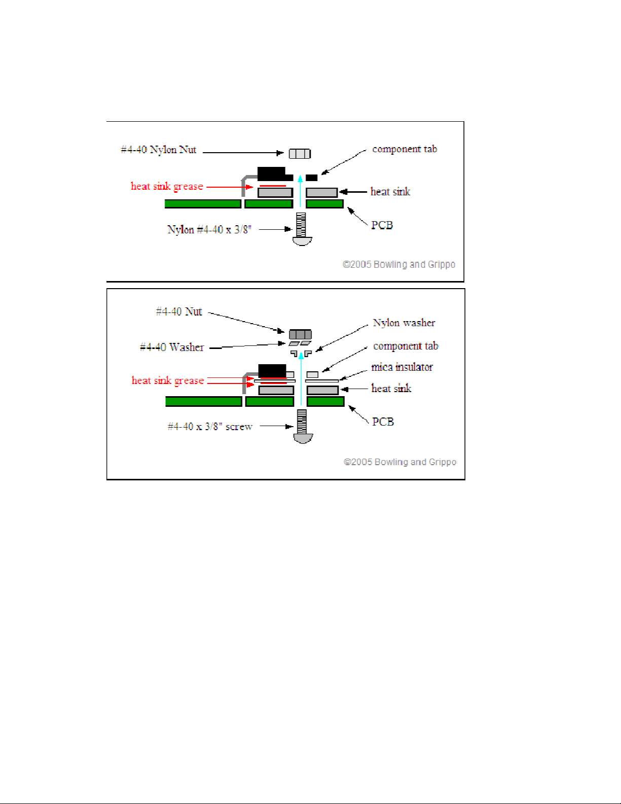
19) Now place the metal strip (heatsink) in place and start fitting the main power transistors, remembering Q9
and Q12 have a piece of mica insulation under them to stop them touching the heatsink!
Note, you can put a screw through R36 and R37’s hole to hold the heatsink in place whilst you put the
transistors in.
Without mica
<>
With mica
<>
20) Find Y1 (crystal) this is very very small. If your building an MS2 then you don't need this so put it out of
the way. If you're building an MS1 then fit it so that the body of the crystal lays on the metal pad above the
holes. You should glue this to the board or very carefully solder it so it doesn't move about.
21) You can now fit all the other components, except for those that you put to one side! I fit the MAP sensor
last, don’t forget to bolt it in place with the plastic screws then solder it in once it's secure. Note, if using metal
screws, don’t tighten them up too much or the sensor case will distort and read incorrectly. This is installed
with the writing facing you, the 'round' side goes towards the board. One of the pins has a small notch out of it
which goes in the hole with 'notch' next to it.

22) R37 and R38 are 'sense' resistors for the current limiting circuits on the injector drivers. Normally these
should be installed.
(If, however, you prefer to do without the current limiting and want to make two spaces on the heatsink bar,
then you can instead link out R37 and R38 by soldering a copper wire between the 2 holes in each. Ensure the
link is flat to the board as you may need a component on the heat sink later on in the build. Remember that
without these current sense resistors, there is no over-current protection on the injector circuits.)
Note: I installed R37 and R38
23) R43 is intended to allow coil current to be measured if you are using the Q16 high current coil driver.
Unless you have access to an oscilloscope and plan on performing this test you won't need it. Either install R43
or link it out. Most people seem to leave it out without the link, so this is what I’ve done.
Testing Stage:
24) The board is now built to a basic level and is ready for a few tests:

a) Start by looking at ALL of the diodes and ensure they are the right way round.
b) Check that you fitted the mica insulators under Q9 and Q12 on the heatsink
and that they look ok.
c) Now you can plug it into your Stim and measure the voltage on the 40 pin
connector U1:
Put the -ve probe of your voltmeter on pin 32 of the 40pin connector (U1) Note,
this is WITHOUT the MS1 or MS2 microprocessor in place!
Put the +ve probe onto pin 20 (Top pin right side)
Ensure you read 5V (+- 0.1V)
d) Keep the +ve probe on pin 20 and move the -ve probe to pin 19 and pin 2,
ensure you have 5V on the meter for both measurments. If its OK goto stage 25.
e) If you don't get 5V then put the -ve probe on the 0V on the proto area and put
the +ve probe onto the left pin of U5 (top left hand side on heatsink) check the
voltage on the meter, it should be 12V (9V if using a battery) if this isn't there
then you have a stim/battery problem as the ECU isn't getting any power. It could
also be a diode in the wrong way round, so check D10, D11, D12 and D13!
f) If they are all OK then check the mica insulation on Q9 and Q12, with an
ohmmeter (mulitmeter) put one probe on the metal heatsink and another on the
metal tab of Q9 and Q12, you should read 300+ Ohms. If you read less then you
have a short, remove the insulator and fix the issue with a new one.
If you have any smoke then its likely you’ve put a diode in the wrong way round,
this will mean finding it and fitting a new component. Once any component
smokes it is no longer any use!

25) MS2 ONLY (MS1 jump to Step 26)
Solder a wire between s12c and JS9, this feeds the stepper motor driver on the MS2 daughter board. Even if
you’re not going to use a stepper idle valve, it is needed to use the outputs for other items,
like tacho, etc, so you might as well fit it now. DON’T FIT THIS LINK IF YOUR USING AN MS1 (black
40 pinned microprocessor)!! You will blow it up!
26)
Idle valves
: Note, you can use the PWM Idle Valve wiring diagram for boost control on MS2 if you're
NOT using a PWM idle valve, it can also be used to drive a relay).
i)
Stepper Idle Valve (MS2 ONLY)
: If using an MS2 and a 4 wired idle device then solder
wires from:
a) JS0 to IAC1A
b) JS1 to IAC1B
c) JS2 to IAC2A
d) JS3 to IAC2B
e) Solder components Q4, Q20 and R39 in place. Note, this gives you a programmable output
that can drive a relay e.g. cooling fan on FIdle (Pin 30 of the db37)
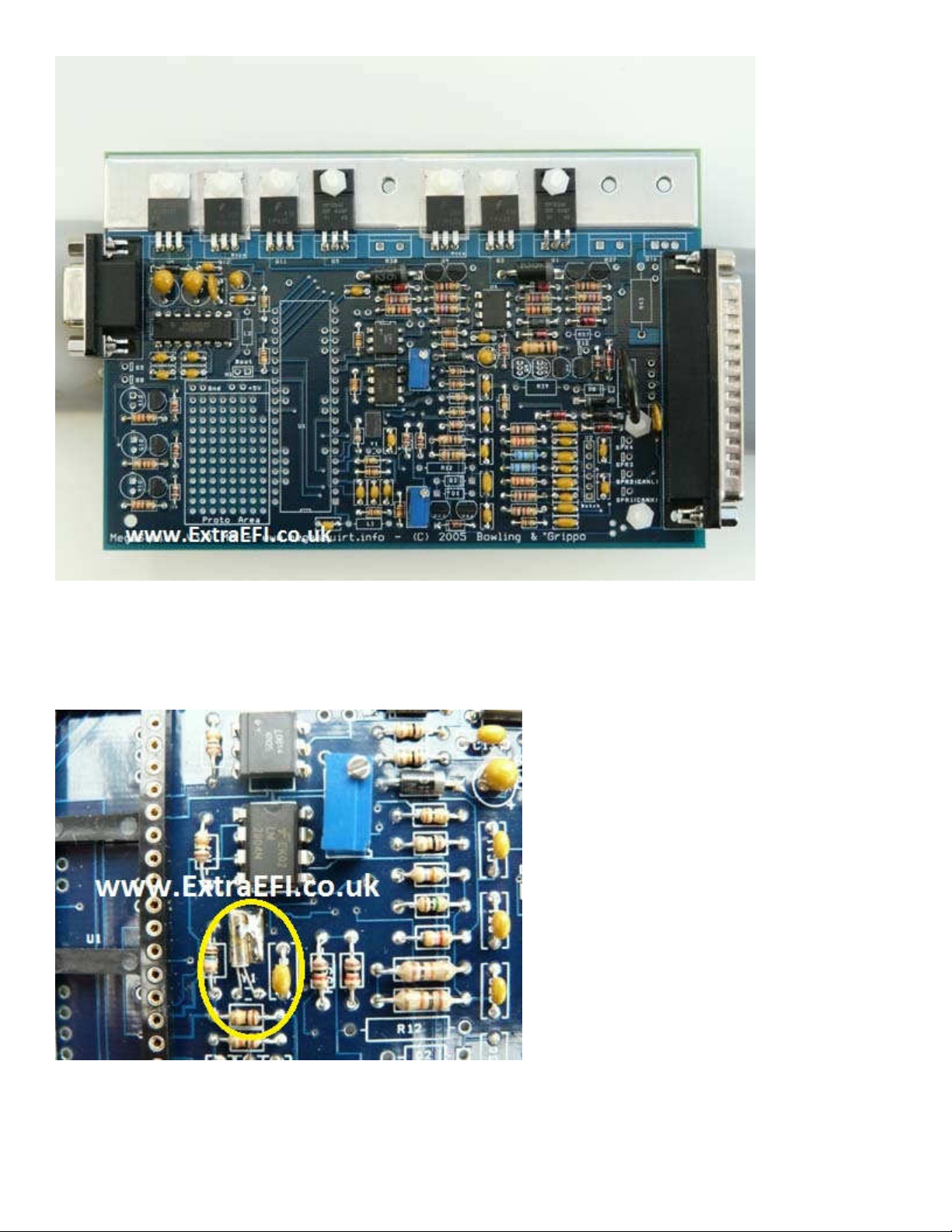
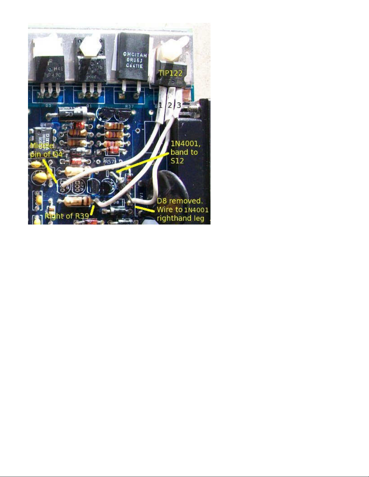
ii) PWM Idle Valve: (MS1 or MS2) 2, 3 wired devices need a TIP122 and mica insulation.
a) Cut the legs of the TIP122 so they are half the length they were as new.
b) Fit a piece of mica insulation under it and using plastic screws bolt it to the heatsink in a
spare position, or bolt onto the case.
c) Solder a wire from the centre pin of Q4 to the pin 1 of the TIP122.
d) Solder a wire from the right of R39 to the pin 3 of the TIP122
(Some installs might connect pin 3 to the bottom of R43, that's fine too.)
e) Ensure D8 is not fitted or remove it if it is.
f) Get an IN4001 (you should have a spare from D2) and install the non banded end into the
right hole of D8 and the banded end to S12.
g) Solder a wire from the non-banded side of the 1N4001 diode to pin 2 of the TIP122.
iii) No Idle Valve: (MS1 and MS2)
a) Solder components Q4, Q20 and R39 in place. Note, this gives you a programmable output
that can drive a relay e.g. cooling fan on FIdle (Pin 30 of the db37)
26)
Trigger input:
Remember you have already decided between VR, Hall or coil –ve. Note, Hall input
covers all inputs like VAST, EDIS PIP, GM HEI, etc.
See the specific manual for you’re engine's input to find out if it’s 5V or 12V. If in doubt measure the voltage
with the engine stopped and ignition on.
Hall sensors Only
(EDIS, VAST, luminition, etc):
a) Link OPTOOUT to TSEL
b) Solder a wire between TACHSELECT and XG1
c) For 5V inputs fit a 470R resistor into the position of R12
d) For 5V inputs solder a wire between the top hole of C30 and 5V on the proto area.
Following section is from http://www.msextra.com/doc/ms2extra/MS2-Extra_4g63.htm:
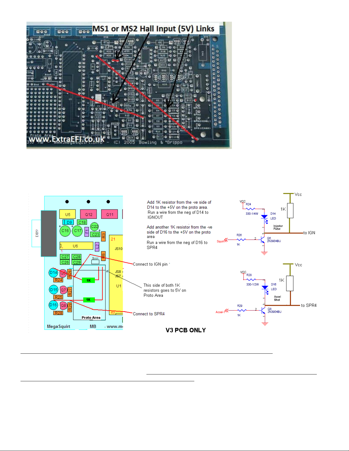
Output Mods for V3.0 PCB
Spark Invert mod from http://www.miataturbo.net/megasquirt-18/better-spark-out-circuit-33 64/
The solution is to configure the spark outputs such that they are on when the CPU’s output pins are on,
and off when the CPU’s output pins are off. We could achieve this by using a PNP transistor on the CPU
output pin PNPs have the opposite control polarity of NPNs) (edit: no, that wouldn't work) however since
NPNs are already a part of the the modkit packages of the various distributors, I’ve chosen a route which
will achieve the same results at the same cost, without requiring that new devices be added to anybody’s
inventory.
So essentially what I have done is to place a second set of NPN transistors after the first set, to un-invert
the signals which Q6 and Q8 have inverted:

BM note:
Invert spark A and spark B on MS board so Spark A goes to pin 31 and Spark B goes to pin 36.
(http://www.miataturbo.net/megasquirt-18/ms2-standalone-stock-ignitor-70414/).
As you can see, we’re using the natural pullup of the existing LED to drive the base of the new transistor,

which is connected to the collector of Q6/Q8 where the old spark output used to be. In this configuration,
the output at the collector of the new transistors is exactly the opposite of what’s happening at the
collectors of Q6/Q8, which is turn have always been the opposite of what’s happening at the CPU pins
driving them. So, if the CPU is inactive, the spark outputs will be off.
NOTE: Having performed this modification, YOU MUST SET “SPA K OUTPUT INVE TED = YES”.
Back to MS2 Extra build:
27) Next we need to check that everything is OK before we plug in the microprocessor. Plug the board into your
stim and power it up.
Ensure you have 0-5V on TSEL, if you get any more than 5V you have a wiring issue with the trigger input
side. As long as you have 0-5V you can proceed to step 28.
28) Now your ready to test the board with the microprocessor in place. Fit U1 (black 40 pinned microprocessor
for MS1 or a daughter board for MS2) into the 40 pin connector.
Plug the ECU into your stim and turn the power on.
Feel the top row of power transistors, if they get hot at all turn the power off and check for faults.
If the microprocessor gets hot then turn it off. Slightly warm is OK, if any part is too hot to touch then there is a
fault!
29) Next you need to figure out your ignition driver(s) See the MS1-Extra Ignition Manuals or MS2-Extra
manuals for information specifically for your setup. BM Note: done this above.
30) Once the spark drivers are sorted, your ready to load the code into your MS-Extra ECU.
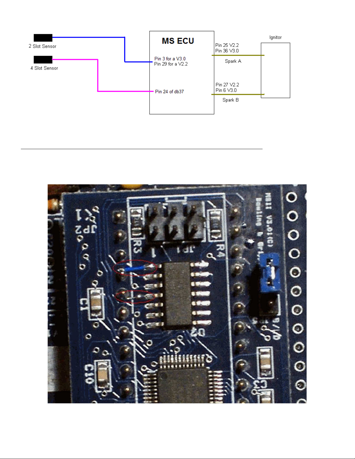
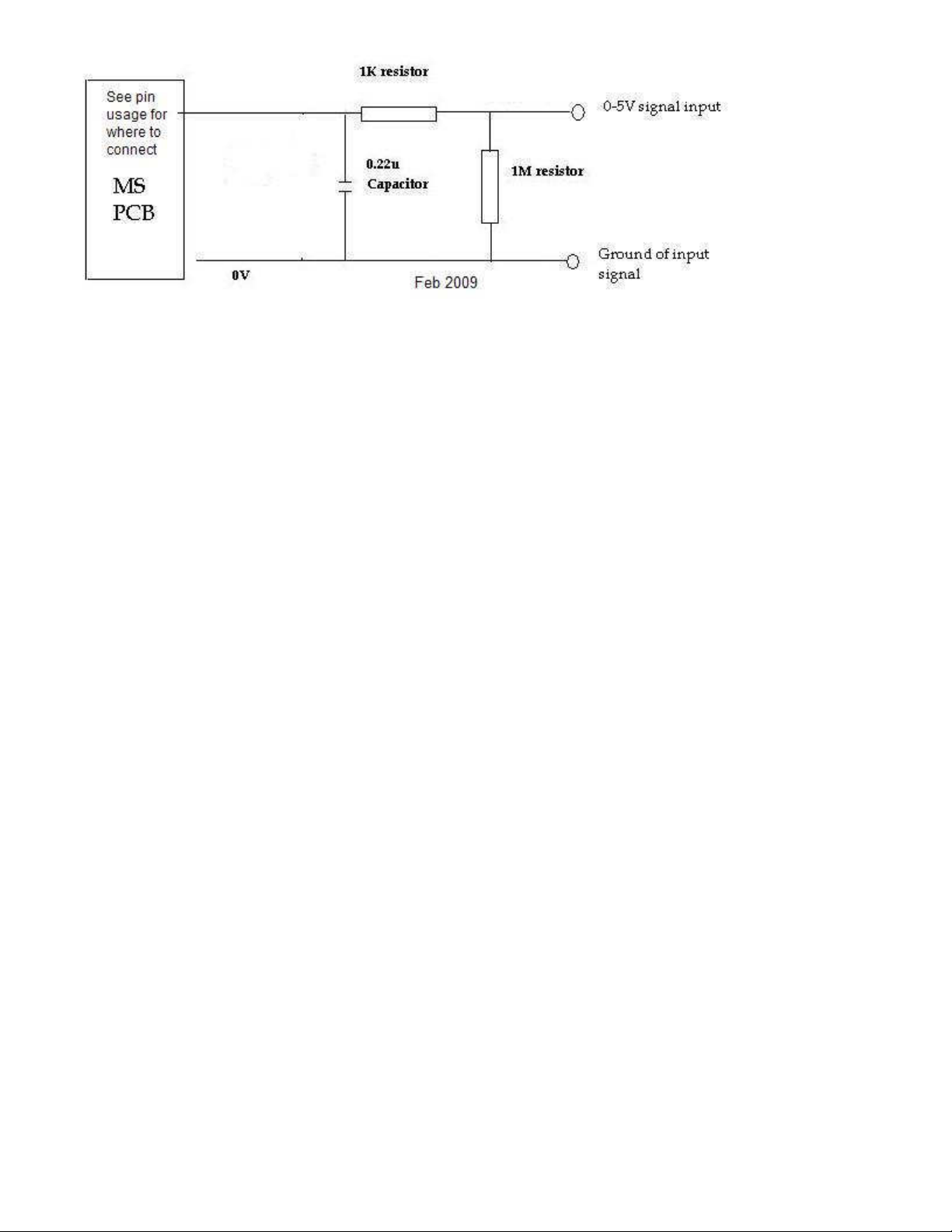
Check Miata 4G63 second input circuit (http://www.msextra.com/doc/ms2extra/MS2-Extra_4g63.htm#2hall)
Second Trigger Input (2 slot Sensor on CAS)
Second Hall Sensor Circuit - this needs to be built for Both V3.0 and V2.2 Boards.
2 slot sensor input for CAS on pin3 of the DB37 connector on a V3.0 PCB
2 slot sensor input for CAS on pin29 of the DB37 connector on a V2.2 PCB
BM Note: 1k resistor already exists on MS2 daughterboard.
Schematic:
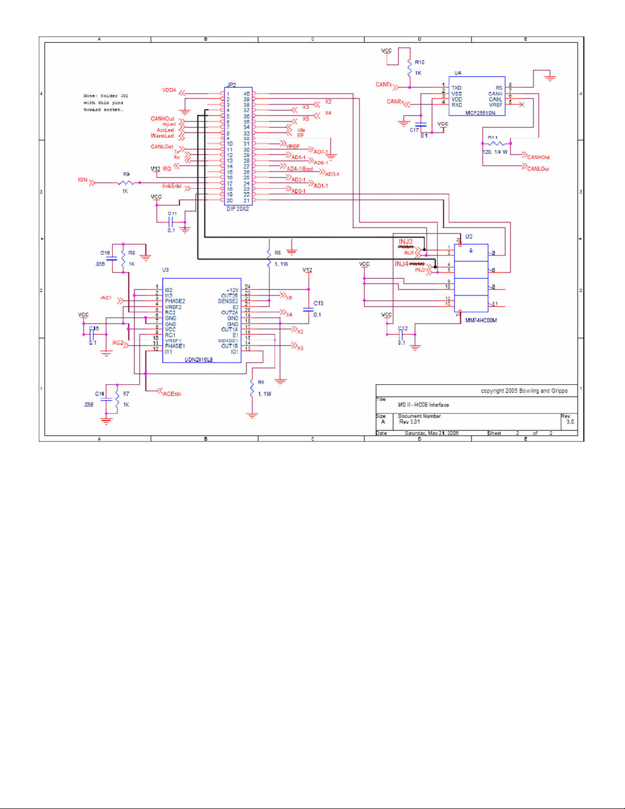
Installation of 4-channel injector board (http://jbperf.com/sequential/index.html#ms2mods):
The picture below shows the modification which connects pin 1 of the NAND gate chip (U2) on the MS2 card to pin
of the 0-pin header and pin of U2 to pin 5 of the header.
With that modification, pins 3 and 7 of the MS2 CPU can be used for injector channels 3 and , respectively, as shown
below.

These new signals are taken at the input of the NAND gat chip since it a much more convenient location (closer to the
header pins and more space to solder jumpers). The black lines in the schematic below show the new jumpers
connection. It should be noted also that the CPU pins corresponding to injector channels 1 and 2 are already directly
connected to the 0-pin header at pins 39 and 0.
The picture below shows the placement on the V3.0 board of the injector channels. The standard injector drivers
components can be left on the board but will be unused and will not interfere with injector channels 1 and 2. The
injectors channels 3 and connect to pads originally used for the MS1 clock circuit and require the removal of those
components for proper and safe operation. The injector channel 3 shows 2 pads because they correspond to the same
electrical location (use either one). The components to remove are: R21,C20,C21,R22,R23,Y1,C2 ,C25

MAF Sensor Input (http://www.msextra.com/doc/ms2extra/maf.html)
MAF sensors have at least three wires. GND, power supply, signal.
The power supply is typically 12V and should be taken from a fused source from the main relay.
Signal GND should connect to Megasquirt sensor ground.
If present, Power GND should connect to the engine block along with the other Megasquirt power grounds.
You may choose from either pin 'JS5 (ADC6)' or 'JS4 (ADC7)' either requires a hardware modifications inside
the Megasquirt case. BM Note: I chose JS4.
Assemble the circuit on the prototype area of the mainboard and connect your MAF signal into the case through
a spare pin on the DB37 connector. e.g. One of SPR1,2,3,4 if they are free. BM Note: I chose SPR2, normally
allocated to CAN.


