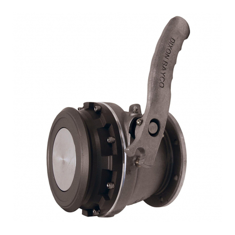
Meggitt F145 Series User manual

Maintenance Manual
PRESSURE FUELLING NOZZLE
F145 Series
MMF145
Revision 6.4
05 January 2015
Meggitt (North Hollywood), Inc. Proprietary Information
The information contained in this document is disclosed in confidence. It is the property of Meggitt (North Hollywood), Inc. and shall not be used,
disclosed to others, or reproduced in whole or in part without the express written consent of Meggitt (North Hollywood), Inc. If consent is given, this
notice shall appear in any such reproduction. These commodities, technology, or software were exported from the United States in accordance with
the export administration regulations. Diversion contrary to U.S. law is prohibited.
SENSITIVE BUT UNCLASSIFIED-EXPORT CONTROLLED-EAR RESTRICTED.
These commodities, technology or software are exported from the United States of America in accordance with the Export Administration
Regulations. ECCN EAR99. Diversion contrary to U.S. law is prohibited.
Copyright © 2015 Meggitt (North Hollywood), Inc.
BASIC MODEL SHOWN

Meggitt Fuelling Products
Maintenance Manual (MMF145)
Pressure Fuelling Nozzle –F145 Series
USE OR DISCLOSURE OF DATA ON THIS PAGE IS SUBJECT TO THE RESTRICTIONS ON THE TITLE PAGE OF THIS DOCUMENT
05 Jan 2015 Revision 6.4 RR
REVISION RECORD
Keep this record in the front of the manual. When you get the revisions, put the revised pages in the
manual. Write the revision number, date issued and your initials on this page.
REV NO.
PAGES
AFFECTED
DESCRIPTION OF CHANGE
DATE
APPROVED
BY
Original 1.0
ALL
Initial Release
02/16/2011
A.B
1.1
ALL
See DCN
05/02/2011
A.B
2.0
ALL
See DCN
05/30/2011
A.B
3.0
ALL
See DCN
06/15/2011
A.B
4.0
ALL
See DCN
09/30/2011
A.B
5.0
ALL
See DCN
01/15/2013
A.B
6.0
ALL
See DCN
01/16/2014
A.B
6.1
ALL
See DCN
03/31/2014
J. M
6.2
RR, B, 35, 39 and 47
See DCN
10/02/2014
J. M
6.3
RR, 4, 6, 38 and 46
See DCN
11/25/2014
J. M
6.4
Title, RR, 28, 31 and 41
See DCN
02/11/2015
J.M

Meggitt Fuelling Products
Maintenance Manual (MMF145)
Pressure Fuelling Nozzle –F145 Series
USE OR DISCLOSURE OF DATA ON THIS PAGE IS SUBJECT TO THE RESTRICTIONS ON THE TITLE PAGE OF THIS DOCUMENT
05 Jan 2015 Revision 6.4 i
TABLE OF CONTENTS
SUBJECT PAGE
IMPORTANT SAFETY INSTRUCTIONS...................................................................................................... A
INTRODUCTION...........................................................................................................................................1
DESCRIPTION AND OPERATION ...............................................................................................................2
SPECIAL TOOLS AND TEST EQUIPMENT .................................................................................................9
TEST........................................................................................................................................................... 10
FAULT ISOLATION..................................................................................................................................... 13
MAINTENANCE ..........................................................................................................................................15
DISASSEMBLY...........................................................................................................................................16
CLEANING..................................................................................................................................................19
CHECK/INSPECTION.................................................................................................................................21
REPAIR....................................................................................................................................................... 24
ASSEMBLY................................................................................................................................................. 30
ILLUSTRATED PARTS LIST....................................................................................................................... 34
LIST OF ILLUSTRATIONS
FIGURE PAGE
Figure 1. Pressure Fuelling Nozzle.............................................................................................................3
Figure 2. Shoulder Bolt Detail................................................................................................................... 23
Figure 3. Latch Ring (3-Slot and 6-Slot) Detail..........................................................................................23
IPL Figure 1. Pressure Fuelling Nozzle (Sheet 1 of 3) ............................................................................. 36
LIST OF TABLES
TABLE PAGE
Table 1. Leading Particulars...................................................................................................................... 5
Table 2. Nozzle Variations (Mod Code Group after F145) .........................................................................6
Table 3. Coupling Variations (Type Number between the Mod and Type Letter Groups)...........................7
Table 4. Swivel Body Inlet Variations (End Type Letter) ............................................................................8
Table 5. Special Tools and Test Equipment ..............................................................................................9
Table 6. Fault Isolation ............................................................................................................................13
Table 7. Parts Information .......................................................................................................................15

Meggitt Fuelling Products
Maintenance Manual (MMF145)
Pressure Fuelling Nozzle –F145 Series
USE OR DISCLOSURE OF DATA ON THIS PAGE IS SUBJECT TO THE RESTRICTIONS ON THE TITLE PAGE OF THIS DOCUMENT
05 Jan 2015 Revision 6.4 ii
LIST OF TABLES - CONTINUED
TABLE PAGE
Table 8. Recommended Cleaning Materials ............................................................................................19
Table 9. Component Checks ...................................................................................................................21

Meggitt Fuelling Products
Maintenance Manual (MMF145)
Pressure Fuelling Nozzle –F145 Series
USE OR DISCLOSURE OF DATA ON THIS PAGE IS SUBJECT TO THE RESTRICTIONS ON THE TITLE PAGE OF THIS DOCUMENT
05 Jan 2015 Revision 6.3 A
IMPORTANT SAFETY INSTRUCTIONS
SAVE THESE INSTRUCTIONS!
This manual contains important instructions that should be followed during installation and maintenance of
the Pressure Fuelling Nozzle (nozzle). The following are general safety precautions that are not related to
specific procedures and therefore do not appear elsewhere in this publication. These are recommended
precautions that personnel must understand and apply during maintenance.
The nozzle is a mechanical device and can be dangerous if incorrectly operated or maintained.
Safety Alert Symbols
Safety alert symbols are used in this manual to identify potential or immediate personal injury hazards. The
safety alert symbol words are explained below:
- indicates an imminently hazardous situation which, if not
avoided, will result in injury or serious injury.
- indicates a potentially hazardous situation which, if not avoided,
could result in injury or serious injury.
- indicates a potentially hazardous situation which, if not avoided,
may result in minor or moderate injury.
- used without the safety alert symbol indicates a potentially
hazardous situation which, if not avoided, may result in
property damage.
WEAR PROTECTIVE CLOTHING
Wear protective clothing (gloves, apron, etc.) approved for the materials and tools being used.
USE APPROVED SAFETY EQUIPMENT
Use only approved equipment and make sure firefighting equipment is readily available.

Meggitt Fuelling Products
Maintenance Manual (MMF145)
Pressure Fuelling Nozzle –F145 Series
USE OR DISCLOSURE OF DATA ON THIS PAGE IS SUBJECT TO THE RESTRICTIONS ON THE TITLE PAGE OF THIS DOCUMENT
05 Jan 2015 Revision 6.3 B
GIVE CLEANERS SPECIAL CARE
When cleaners are being used read and follow the material safety data sheet (MSDS) instructions for
correct handling.
Equipment Safety Information
The following safety information briefly discusses hazards peculiar to the equipment, which are likely to be
encountered during maintenance activity.
GENERAL OPERATING LOCATION PRECAUTIONS
Use only authorized replacement parts or hardware.
Obey Lock-Out/Tag-Out procedures when working on the nozzle and make sure that personnel
protection equipment such as electrical grounds are installed.
Avoid hazardous voltage situations that can result from unsafe conditions such as, but not limited, to
the following:
o Incorrect grounding
o Handling electrical leads or devices with wet hands or on wet ground.
o Damaged electrical wire insulation.
o Incorrect connection of the power terminals.
o Short circuits to ground.
OPERATION AND MAINTENANCE OF FUEL SYSTEMS
BEFORE TURNING THE OPERATING LEVER; MAKE SURE ALL 3 LUGS
OF AIRCRAFT FUELING ADAPTER ARE PROPERLY ENGAGED IN THE
F145J NOZZLE. REFER TO SAFETY BULLETIN 7872 FOR MORE DETAILS.
Protect all fuel lines from damage or puncture. Do not operate the nozzle if a fuel leak is detected.
Do not use flammable solvents for cleaning parts.
Check for tools, rags, or loose parts left in the area before resuming operation.
Do not attempt to remove the nozzle from the system without first isolating it from the line pressure and
venting all of the trapped internal pressure.

Meggitt Fuelling Products
Maintenance Manual (MMF145)
Pressure Fuelling Nozzle –F145 Series
USE OR DISCLOSURE OF DATA ON THIS PAGE IS SUBJECT TO THE RESTRICTIONS ON THE TITLE PAGE OF THIS DOCUMENT
05 Jan 2015 Revision 6.4 1
INTRODUCTION
1. General
The information and procedures contained in this manual have been prepared to assist qualified repair
personnel in off-aircraft maintenance of the Pressure Fuelling Nozzle. The instructions provide
information necessary to perform maintenance functions. The nozzle is manufactured by Meggitt (North
Hollywood), Inc., 12838 Saticoy Street, North Hollywood, California 91605.
2. Scope
The instructions contained in this manual do not claim to cover all details or variations in equipment.
They do not provide for every problem that could occur during installation, operation, or maintenance. If
further information is required, contact Meggitt (North Hollywood), Inc., Product Support Department.
3. Standard Shop Practices
Use approved procedures and safety precautions to prevent damage to the equipment and injury to
personnel.
4. Weights and Measurements
Weights and measurements in this manual are expressed in both English (U.S. customary) and
Metric (SI) units.
5. Revision Service
This manual will be revised, as necessary, to reflect current information.

Meggitt Fuelling Products
Maintenance Manual (MMF145)
Pressure Fuelling Nozzle –F145 Series
USE OR DISCLOSURE OF DATA ON THIS PAGE IS SUBJECT TO THE RESTRICTIONS ON THE TITLE PAGE OF THIS DOCUMENT
05 Jan 2015 Revision 6.4 2
DESCRIPTION AND OPERATION
1. Description
The Pressure Fuelling Nozzle (nozzle) (see Figure 1) provides the means of controlling the flow of fuel
in pressure fuelling operations. The nozzle inlet port couples to a fuelling hose. The outlet port attaches
to the inlet adapter of the system being fueled. The nozzle provides a leak proof connection between
the system being fueled and the fuel supply.
2. Operation
A. Uncoupled
When the nozzle is not coupled to a mating fuel system inlet adapter, its poppet valve is closed, so
that there is no flow or leakage of fuel from the outlet port. The flow control handle that operates
the poppet valve remains locked in the CLOSED position until the nozzle is coupled to the mating
fuel system inlet adapter.
B. Coupling and Opening
When the nozzle is coupled to the mating fuel system inlet adapter, the nose seal of the nozzle is
compressed against the sealing surface of the inlet adapter to form a fluid-tight connection. When
the nozzle is fully engaged and locked to the bayonet flange of the inlet adapter, the flow control
handle is unlocked. Rotation of the flow control handle to the OPEN position opens the poppet
valve, providing a flow passage into the system being fueled. As the system is being fueled, fuel
pressure acts on the floating nose seal of the nozzle to increase the sealing force.
C. Closing and Uncoupling
Rotation of the flow control handle to the CLOSED position closes the poppet valve and the flow
passage into the system being fueled. When the nozzle is unlocked and disengaged from the
bayonet flange of the inlet adapter, the flow control handle is locked in the CLOSED position.
D. Adapters
Suitable attachment adapters such as swivels and/or hose end control valves (HECV) may be
used to adapt the nozzle to any fuel system.

Meggitt Fuelling Products
Maintenance Manual (MMF145)
Pressure Fuelling Nozzle –F145 Series
USE OR DISCLOSURE OF DATA ON THIS PAGE IS SUBJECT TO THE RESTRICTIONS ON THE TITLE PAGE OF THIS DOCUMENT
05 Jan 2015 Revision 6.4 3
Figure 1. Pressure Fuelling Nozzle
(Sheet 1 of 2)
BASIC MODEL
SHOWN
FLOW CONTROL CAM HANDLE
(
SHOWN CLOSED
)
TO OPEN ROTATE HANDLE TO
OPPOSITE SIDE
NOZZLE BODY
DUST COVER
HANDLE ASSEMBLY
(
2
places
)

Meggitt Fuelling Products
Maintenance Manual (MMF145)
Pressure Fuelling Nozzle –F145 Series
USE OR DISCLOSURE OF DATA ON THIS PAGE IS SUBJECT TO THE RESTRICTIONS ON THE TITLE PAGE OF THIS DOCUMENT
05 Jan 2015 Revision 6.4 4
GROUNDING CABLE
(MODEL A)
VACUUM
BREAKER
(MODEL B)
PRESSURE
GAUGE
(MODEL M)
DRAG RING
(MODEL F)
STIRRUP HANDLES
(MODEL C)
BASIC MODEL
F145
SWIVEL ADAPTER
(MODEL G1, H1, L1, N1, P,
Q, R, 3, 3†, 4, 4†, 6†, 7, 7†)
INTERLOCK STORAGE
BRACKET
(MODEL S)
(Alternate locations Model B, M)
SWIVEL ADAPTER
(MODEL 8†, 9, 9†)
COUPLING ASSY
(MODEL 9, 9†)
LONG HANDLES (10")
(MODEL K)
STRAINER
(MODEL T, U, V,
3, 3†, 4, 4†, 6†, 7,
7†, 8†, 9, 9†)
HECV
(MODEL G1, H1,
L1, N1)
COUPLING ASSY
(MODEL 3, 3†, 4,
4†, 6†, 7, 7†)
DRYBREAK ASSY
(MODEL 8†)
SPECIAL
COUPLING
WITH O-RING
(MODEL Q)
FLIGHT
ADAPTER
ASSY
(MODEL R)
Figure 1. Pressure Fuelling Nozzle
(Sheet 2)

Meggitt Fuelling Products
Maintenance Manual (MMF145)
Pressure Fuelling Nozzle –F145 Series
USE OR DISCLOSURE OF DATA ON THIS PAGE IS SUBJECT TO THE RESTRICTIONS ON THE TITLE PAGE OF THIS DOCUMENT
05 Jan 2015 Revision 6.4 5
3. Leading Particulars
For the leading particulars refer to Table 1.
Table 1. Leading Particulars
Service Fluid ........................................................................................... Automotive and Aviation Fuels
Performance:
Operating Pressure ........................................................................................ 120 psig (827 kPaG)
Temperature:
Ambient.................................................................................................. -40 to 165°F (-40 to 74°C)
Fluid ....................................................................................................... -40 to 165°F (-40 to 74°C)
Mating Inlet Swivels ....................................................................... F595 HECV, F575/F584, F577/F582,
F581 Swivels, F1516/F596 Dry Disconnect
4. Model Variations
The F145 series nozzle is a straight-in fuelling nozzle with a swivel inlet. It is equipped with bicycle-type
grip handles and a dust cover. A flanged swivel adapter is not supplied with the basic nozzle, but can
be ordered as a variation. Refer to Tables 2, 3, and 4 for the available F145 series nozzle variations. An
explanation of the F145 series part numbering system is as follows:
BASIC PART NUMBER
MODIFICATION LETTER GROUP
COUPLING TYPE
SWIVEL BODY TYPE
F145 XXX X X
P/N
P/N Example: F145APV7A - This nozzle is equipped with a ground cable and has a flanged swivel
adapter and a 100 mesh strainer. The coupling is the 2.5 inch aluminum type with wire raceways to
mate with the F577/F582 swivel body. The swivel body has a 2.5 inch NPT inlet.

Meggitt Fuelling Products
Maintenance Manual (MMF145)
Pressure Fuelling Nozzle –F145 Series
USE OR DISCLOSURE OF DATA ON THIS PAGE IS SUBJECT TO THE RESTRICTIONS ON THE TITLE PAGE OF THIS DOCUMENT
05 Jan 2015 Revision 6.4 6
Table 2. Nozzle Variations (Mod Code Group after F145)
Examples: F145APV7A, F145BG7A
NOZZLE MOD
LETTER
DESCRIPTION
A
Adds Ground Cable
B
Adds Vacuum Breaker
C
Changes to Stirrup Handles
D
Change nose seal to F117 (1 Piece)
E
Ring Handles
F
Adds Drag Ring
G1
Adds 45 PSI HECV (Flanged)
G2
(Inactive)
G3
Adds additional 45 PSI HECV (Flanged Connection)
H1
Adds 35 PSI HECV (Flanged)
H2
(Inactive)
H3
Adds additional 35 PSI HECV (Flanged Connection)
J
Six (6) Slot Configuration
K
Changes to 10” Long Handles
L1
Adds 50 PSI HECV (Flanged)
L2
(Inactive)
L3
Adds additional 50 PSI HECV (Flanged Connection)
M
Adds 0-100 PSI Pressure Gauge
N1
Adds 55 PSI HECV (Flanged)
N2
(Inactive)
N3
Adds additional 55 PSI HECV (Flanged Connection)
P
Adds Flanged Swivel Adapter
Q
Adds Adapter for J.C.C. Inlet Flange
R
Adds Flight Adapter
Note: Use of a 100 mesh filter (Customer Furnished Equipment CFE))
is recommended.
S
Interlock Storage Bracket
T
Adds 40 Mesh Strainer

Meggitt Fuelling Products
Maintenance Manual (MMF145)
Pressure Fuelling Nozzle –F145 Series
USE OR DISCLOSURE OF DATA ON THIS PAGE IS SUBJECT TO THE RESTRICTIONS ON THE TITLE PAGE OF THIS DOCUMENT
05 Jan 2015 Revision 6.4 7
Table 2. Nozzle Variations (Mod Code Group after F145) (continued)
NOZZLE MOD
LETTER
DESCRIPTION
U
Adds 60 Mesh Strainer
V
Adds 100 Mesh Strainer
W
TBD
X
TBD
Y
TBD
Z
TBD
Table 3. Coupling Variations (Type Number between the Mod and Type Letter Groups)
Examples: F145APV7A (Basic model w/ grounding cable, swivel adapter flange, 100 mesh 3”
strainer, F582E coupling assembly with 2-1/2 NPT inlet,
COUPLING TYPE
NUMBER
DESCRIPTION
3
Standard 3-inch aluminum coupling with corrosion resistant steel wire
races to mate with F575/F584 swivel body (uses 3-inch strainer)
*When ordering less HECV must include “P” modification
4
Standard 3-inch aluminum coupling with corrosion resistant steel wire
races to mate with F596 dry disconnect swivel assembly (uses 3-inch
strainer)
*When ordering less HECV must include “P” modification
6
Standard 2½-inch aluminum coupling with corrosion resistant steel wire
races to mate with F1516 dry disconnect swivel body (uses 2½-inch
strainer)
*When ordering less HECV must include “P” modification
7
Standard 2½-inch aluminum coupling with corrosion resistant steel wire
races to mate with F577/F582 swivel body (uses 2½-inch strainer)
*When ordering less HECV must include “P” modification
8
Adds F1516 dry disconnect with integral coupling
*Option can only be ordered less HECV mod
9
Adds 2½” integral coupling, straight
*Option can only be ordered less HECV mod

Meggitt Fuelling Products
Maintenance Manual (MMF145)
Pressure Fuelling Nozzle –F145 Series
USE OR DISCLOSURE OF DATA ON THIS PAGE IS SUBJECT TO THE RESTRICTIONS ON THE TITLE PAGE OF THIS DOCUMENT
05 Jan 2015 Revision 6.4 8
Table 4. Swivel Body Inlet Variations (End Type Letter)
Examples: F145APV7A
SWIVEL BODY TYPE
LETTER
DESCRIPTION
A
2½-inch ANPT inlet. Available for coupling types 3, 4, 6 or 7 only.
B
2½-inch BSPPL inlet. Available for coupling types 3, 4, 6 or 7 only.
C
3-inch ANPT inlet. Available for coupling types 3, 4, 6 or 7 only.
D
2-inch ANPT inlet. Available for coupling types 3, 4, 6 or 7 only.
E
3-inch BSPPL inlet. Available for coupling types 3, 4, 6 or 7 only.
F
2-inch BSPPL inlet. Available for coupling type 6 only.
G
3-inch BSPPL inlet. Available for coupling type 7 only.
K
4-inch ANPT inlet. Available for coupling type 7 only.
T
2-inch female Camlock inlet. Available for coupling type 7 only.
U
4-inch female Camlock inlet. Available for coupling type 7 only.
V
3½-inch ANPT inlet. Available for coupling type 7 only.
X
2-inch BSPPL inlet. Available for coupling type 7 only.

Meggitt Fuelling Products
Maintenance Manual (MMF145)
Pressure Fuelling Nozzle –F145 Series
USE OR DISCLOSURE OF DATA ON THIS PAGE IS SUBJECT TO THE RESTRICTIONS ON THE TITLE PAGE OF THIS DOCUMENT
05 Jan 2015 Revision 6.4 9
SPECIAL TOOLS AND TEST EQUIPMENT
1. General
For special tools and test equipment recommended for maintenance of the nozzle refer to Table 5.
Table 5. Special Tools and Test Equipment
PART
NUMBER
CAGE
DESCRIPTION
APPLICATION
F65-0-1130
79318
Nose Seal Test Fixture
Leakage testing of the nose seal
F65-0-2083
79318
Test Fixture
To accommodate fluid pressure source
GTP-8963
32218
Gammon Gauge
Check for wear on mating 3 lug adapter
T-90465
79318
Ball Tool
For removal and installation of swivel ball bearing
T-90466
79318
Nose Seal Removal Tool
For removing nozzle seat in 3 and 6 slot nozzles
2878018
79318
Test Plug, 3-inch ANPT
Leakage testing of 3-inch NPT connections
2878019
79318
Test Plug, 3-inch BSPPL
Leakage testing of 3-inch BSPPL connections
2878020
79318
Test Plug, 2½-inch ANPT
Leakage testing of 2½-inch NPT connections
2878021
79318
Test Plug, 2½-inch BSPPL
Leakage testing of 2½-inch BSPPL connections

Meggitt Fuelling Products
Maintenance Manual (MMF145)
Pressure Fuelling Nozzle –F145 Series
USE OR DISCLOSURE OF DATA ON THIS PAGE IS SUBJECT TO THE RESTRICTIONS ON THE TITLE PAGE OF THIS DOCUMENT
05 Jan 2015 Revision 6.4 10
TEST
1. General
Perform all tests using Stoddard solvent (or equivalent) as the test fluid, supplied by a 0 to 180 psig
(0 to 827 kPaG) test stand. Use only petroleum jelly as a lubricant to aid in the assembly of seals and
O-rings.
2. Functional Test
To functional test the nozzle (see IPL Figure 1), do as follows:
A. Place the nozzle in the test fixture (P/N F65-0-1130) and use handles (52, 52A or 52B) to rotate
nozzle clockwise and lock nozzle to test fixture.
B. Use knob (36) on cam handle (38) to set the position to OPEN and then to CLOSED.
Note: The cam handle (38) shall operate freely with no mechanical interference or binding. If
binding occurs refer to REPAIR section.
C. Use the handles (52, 52A or 52B) to rotate the nozzle counter clockwise to unlock it from the test
fixture.
Note: The nozzle shall lock and unlock freely from the test fixture without binding. If binding
occurs refer to REPAIR section. The nozzle body shall rotate approximately 30° when
connecting to the adapter. If nozzle over rotates, refer to the REPAIR section.
D. Do steps A thru D three times.
3. Leakage Test (Basic, G1, G2, H1, H2, L1, L2, N1, N2, and P)
Note: Adapter Swivel Assembly (71) must be installed on “BASIC” nozzle for leakage test. For Mods;
G, H1, L1, L2, N1 and N2; the lockout device p/n 941020-101 shall be installed in the vent port
of the nose end control valve.
A. Make sure the nozzle is in the CLOSED position (see Figure 1).
B. Place the nozzle in the test fixture (P/N F65-0-1130) and rotate nozzle clockwise to lock nozzle to
test fixture.

Meggitt Fuelling Products
Maintenance Manual (MMF145)
Pressure Fuelling Nozzle –F145 Series
USE OR DISCLOSURE OF DATA ON THIS PAGE IS SUBJECT TO THE RESTRICTIONS ON THE TITLE PAGE OF THIS DOCUMENT
05 Jan 2015 Revision 6.4 11
C. Use knob (IPL Figure 1, 36) and cam handle (38) to set the nozzle in the open position.
D. Place the test fixture (P/N F65-0-2083) on Adapter Swivel Assembly (71) and secure with
washer (74) lock washer (73) and screws (72).
E. Test fixture (P/N F65-0-2083) has a 1/4 inch NPT port for pressure source. Attach applicable
adapter to connect pressure source to test fixture (P/N F65-0-2083).
F. Test fixture (P/N F65-0-1130) has a 1/4 inch NPT tap for a test plug. Fill nozzle with test fluid and
let air bleed thru the hole in test fixture (P/N F65-0-1130). Plug up test fixture (P/N F65-0-1130)
after all air has escaped from the nozzle.
G. Apply 180 psig of fluid pressure to the nozzle for 5 minute. Then reduce pressure to 0 psig.
H. Use knob (36) on handle (38) to set the nozzle in the closed position.
I. Disconnect nozzle from test fixture (F65-0-1130).
J. Apply 180 psig of fluid pressure to the nozzle for 5 minute. Then reduce pressure to 0 psig.
K. There must not be any leakage from the exterior of the nozzle, thru any seals or from the plugs (3).
L. Remove all test fixtures from the nozzle.
4. Leakage Test (3, 3†, 4, 4†, 6, 6†, 7, 7†, 8 and 9)
A. Make sure the nozzle is in the CLOSED position (see Figure 1)
B. Place the nozzle in the test fixture (P/N F65-0-1130) and rotate nozzle clockwise to lock nozzle to
test fixture).
C. Rotate knob (IPL Figure 1, 36) on cam handle (38) and place the nozzle in the open position.
D. Install matching test plugs (P/N‟s 2878018, 2878019, 2878020 or 2878021) in the inlet port of the
nozzle under test.
E. Test plugs (P/N‟s 2878018, 2878019, 2878020 or 2878021) have a 1/4 inch NPT port for pressure
source. Attach appropriate connector to connect pressure source to the test plugs (P/N‟s 2878018,
2878019, 2878020 or 2878021).

Meggitt Fuelling Products
Maintenance Manual (MMF145)
Pressure Fuelling Nozzle –F145 Series
USE OR DISCLOSURE OF DATA ON THIS PAGE IS SUBJECT TO THE RESTRICTIONS ON THE TITLE PAGE OF THIS DOCUMENT
05 Jan 2015 Revision 6.4 12
F. Test fixture (P/N F65-0-1130) has a 1/4 inch NPT tap for a test plug. Fill nozzle with test fluid and
let air bleed thru the hole in test fixture (P/N F65-0-1130). Plug up test fixture (P/N F65-0-1130)
after all air has escaped from the nozzle.
G. Apply 180 psig of fluid pressure to the nozzle for 5 minute. Then reduce pressure to 0 psig.
H. Use knob (IPL Figure 1, 36) on handle (38) to set the nozzle in the closed position.
I. Disconnect nozzle from test fixture (P/N F65-0-1130).
J. Apply 180 psig of fluid pressure to the nozzle for 5 minute. Then reduce pressure to 0 psig.
K. There must not be any leakage from the exterior of the nozzle, or from the plugs (3).
L. Remove all test fixtures and test plugs from the nozzle.

Meggitt Fuelling Products
Maintenance Manual (MMF145)
Pressure Fuelling Nozzle –F145 Series
USE OR DISCLOSURE OF DATA ON THIS PAGE IS SUBJECT TO THE RESTRICTIONS ON THE TITLE PAGE OF THIS DOCUMENT
05 Jan 2015 Revision 6.4 13
FAULT ISOLATION
1. General
This section contains fault isolation procedures for the nozzle. Operate the nozzle in accordance with
the Operation section, if the nozzle fails to operate correctly refer to Table 6 and select the appropriate
action. Table 6 identifies the Fault, Probable Cause and Corrective Action.
Table 6. Fault Isolation
FAULT
PROBABLE CAUSE
CORRECTIVE ACTION
Leakage at the poppet seat when
closed
Damaged or worn nose seal seat
(IPL Figure 1, 2 and 68)
Check condition and if necessary
replace nose seal seat.
Damaged or worn poppet (20)
Check condition and if necessary
replace the poppet.
Damaged or worn O-ring (4)
Check condition and if necessary
replace the O-ring.
Damaged or worn shoulder bolt (31)
Check condition and if necessary
replace the shoulder bolt.
Leakage past nose seal when
coupled
Nose seal seat (2, 68) damaged
Check condition and if necessary
replace the nose seal seat.
Mating flange and locking lugs on
airplane fuel system inlet adapter
damaged or worn
Check the three locking lugs of the
bayonet flange for wear,
straightness, and alignment. If they
are damaged, the airplane inlet
adapter must be replaced.
Leakage past flow control handle
shaft
O-ring (25) or backup ring (26)
damaged, twisted, or incorrectly
installed
Check condition and if necessary
replace the O-ring or backup
ring (26)

Meggitt Fuelling Products
Maintenance Manual (MMF145)
Pressure Fuelling Nozzle –F145 Series
USE OR DISCLOSURE OF DATA ON THIS PAGE IS SUBJECT TO THE RESTRICTIONS ON THE TITLE PAGE OF THIS DOCUMENT
05 Jan 2015 Revision 6.4 14
Table 6. Fault Isolation (continued)
FAULT
PROBABLE CAUSE
CORRECTIVE ACTION
Leakage at swivel adapter
Damaged or worn O-ring (6)
Check condition and if necessary
replace the O-ring.
Damaged or worn cap seal (76)
Check condition and if necessary
replace the cap seal.
This manual suits for next models
1
Table of contents
Other Meggitt Control Unit manuals
Popular Control Unit manuals by other brands

Emerson
Emerson Fisher Baumann 87000 instruction manual

Quantum Data
Quantum Data 980 Application guide
Quanser
Quanser Q1-cRIO quick start guide
Sirona
Sirona XIOS XG Operating instructions and installation
Aventics
Aventics CL03 operating instructions
Control Techniques
Control Techniques EMERSON DeviceNet user guide
