Section I / Page 4
INSTALLATION
Before installing the PowerMaster® Valve, all air lines in
the system should be blown clean to remove any
moisture or loose material. To further ensure long,
trouble-free service, an efficient filter should be installed
in the air line on the supply side of the valve. Although
the valve is lubricated at the factory, an air line lubricator
is also recommended for high-cyclic applications. See
Catalog SC-500 for complete air line conditioner units.
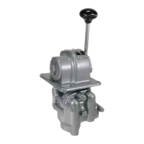
Install the valve in any convenient position but, if installed
with the spool axis vertical, a spring-returned model
provides more positive operation. The preferred
mounting for all models is horizontal.
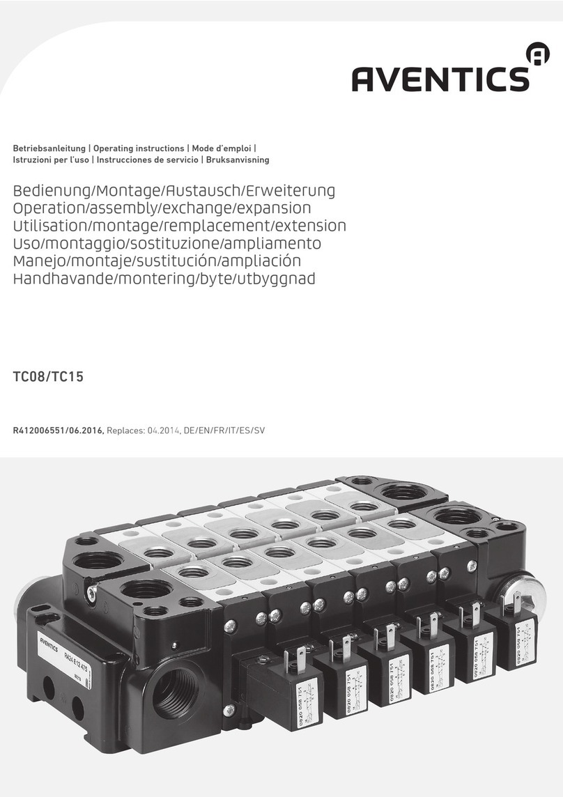
The valve is offered in four port sizes, both tapped body
and subplate mounted models. Port sizes are 1/4, 3/8,
1/2 & 3/4, inches NPTF. Port numbers or designations
are marked on the top of the valve body.
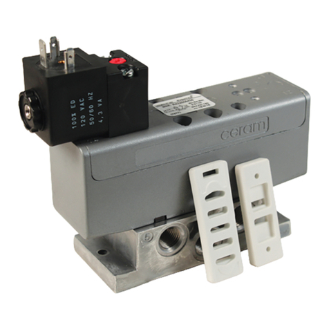
Solenoid operated models have an external pilot port in
the operator that is tapped 1/4-18 inch NPTF. This port is
plugged on solenoid operators when the valve is
internally piloted.
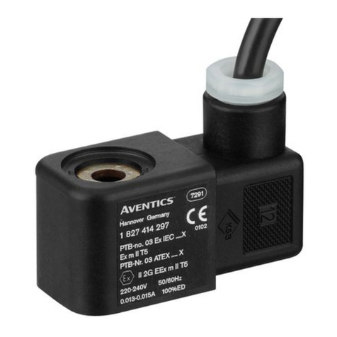
Prior to connecting power supply, be sure that the coils
match the power supply. Voltage characteristics for
solenoid operators are indicated by the suffix of the piece
number on the nameplate of the valve. Voltage of a
solenoid coil is indicated on the coil nameplate.
OPERATION
Temperature Range - 20°F to +160°F (+29°C to 71°C)
Pressures
Valve inlet and air pilot maximum air pressure: 150 psi
(10.3 bar) Minimum air pilot pressure: 15 psi (1.0 bar)
without return springs; 50 psi (3.4 bar) for 1/4” and 3/8”
valves with return springs; 40 psi (2.8 bar) for 1/2” and
3/4” valves with return springs.
Any PowerMaster Valve can be provided to obtain either
two or three position operation.
Three-position valves offer a choice of center functions,
determined by the spool used (see Page 3). These
functions are closed center (all ports blocked), inlet open
center (supply port open to both delivery ports), and
exhaust open center (delivery ports open to the exhaust
port).
The air pilot signal is controlled in solenoid operators by
energizing the solenoid coil to open and close a 3-way
valve in the operators. When electrical power is not
present, the valve may be operated by depressing the
manual override button located on the side of the operator.
Although the solenoid coil may be energized for extended
periods of time, it is better practice to design your electrical
circuit so the coil is de-energized for the extended period,
and energized for the shorter period.
ADJUSTMENTS
No adjustments are require on the PowerMaster Valve.
MAINTENANCE
Tapped body valves may be serviced by shutting off and
venting the main air supply, but removal of the valve from
its mounting is recommended. On subplate mounted
models, the complete valve portion can be removed from
the subplate for servicing without disconnecting piping;
however, air pressure must be shut off and vented.
If a solenoid operated valve fails to operate, depressing the
manual override button on the end of the operator should
quickly indicate whether the trouble is electrical or
mechanical. If required, the solenoid coil can be easily
replaced by removing the top lock nut & slipping off the
solenoid.
PowerMaster Valves are lubricated at the factory for long,
trouble-free service. An efficient air line lubricator will
further extend the service life of the valve. When no
additional lubrication is provided, the valve should be
disassembled every one million cycles for lubrication,
cleaning, and inspection. Clean all metal parts with a
nonflammable solvent and wash all rubber parts with soap
and water. Rinse thoroughly and blow dry with a low-
pressure air jet. When applicable, check the internal pilot
ports in the valve body to make sure the passages are
open.
Replace any parts that are damaged or worn, giving
particular attention to the seal rings (8) in the valve portion.
Repair parts for valve portions and solenoid operators
(Page 3), are available in convenient repair kit form as
shown under the appropriate parts list.
When reassembling the valve portion, one new spacer (9)
should be installed in the stack of spacers and sealing
rings (8) to make the necessary compression in the post
sockets and assure a tight seal stack. Place the new
spacer in the center of the valve body, with sealing rings
and spacers added on each side as assembly of the stack
proceeds. Lubricate each seal with Dow Corning 55M. Tilt
the sealing rings as they are inserted into the valve body to
avoid cutting or damage from sliding over port openings.
Lubricate all metal-to-metal surfaces with Number 107
Lubriplate and all rubber parts with Shell Alvania EP-RO
Grease.
SERVICE INFORMATION
