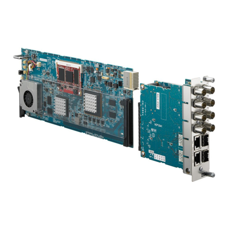
Sony BVE-700 User manual

Editing Control Unit
BVE-700
Operation Manual
1st Edition (Revised 1) [English]

WARNING
To prevent fire or shock hazard,
do not expose the unit to rain or
moisture.
To avoid electrical shock, do not
open the cabinet. Refer
servicing to qualified personnel
only.
THIS APPARATUS MUST BE EARTHED.
For the customers in the USA
This equipment has been tested and found
to comply with the limits for a Class A
digital device, pursuant to Part 15 of the
FCC Rules. These limits are designed to
provide reasonable protection against
harmful interference when the equipment is
operated in a commercial environment.
This equipment generates, uses, and can
radiate radio frequency energy and, if not
installed and used in accordance with the
instruction manual, may cause harmful
interference to radio communications.
Operation of this equipment in a residential
area is likely to cause harmful interference
in which case the user will be required to
correct the interference at his own
expense.
You are cautioned that any changes or
modifications not expressly approved in
this manual could void your authority to
operate this equipment.
The shielded interface cable recommended
in this manual must be used with this
equipment in order to comply with the limits
for a digital device pursuant to Subpart B of
Part 15 of FCC Rules.
This symbol is intended to
alert the user to the
presence of important
operating and maintenance
(servicing) instructions in the
literature accompanying the
appliance.
WARNING: THIS WARNING IS
APPLICABLE FOR USA ONLY.
If used in USA, use the UL LISTED power
cord specified below.
DO NOT USE ANY OTHER POWER
CORD.
Plug Cap Parallel blade with ground
pin
(NEMA 5-15P Configuration)
Cord Type SJT, three 16 or 18
AWG wires
Length Less than 2.5 m (8 ft 3 in)
Rating Minimum 10 A, 125 V
Using this unit at a voltage other than 120V
may require the use of a different line cord
or attachment plug, or both. To reduce the
risk of fire or electric shock, refer servicing
to qualified service personnel.

AVERTISSEMENT
Afin d’éviter tout risque
d’incendie ou d’électrocution, ne
pas exposer cet appareil à la
pluie ou à l’humidité.
Afin d’écarter tout risque
d’électrocution, garder le coffret
fermé. Ne confier l’entretien de
l’appareil qu’à un personnel
qualifié.
CET APPAREIL DOIT ÊTRE RELIÉ À LA
TERRE.
VORSICHT
Um Feuergefahr und die Gefahr
eines elektrischen Schlages zu
vermeiden, darf das Gerät
weder Regen noch Feuchtigkeit
ausgesetzt werden.
Um einen elektrischen Schlag
zu vermeiden, darf das
Gehäuse nicht geöffnet werden.
Überlassen Sie
Wartungsarbeiten stets nur
qualifiziertem Fachpersonal.
DIESES GERÄT MUSS GEERDET
WERDEN.
For the customers in Europe
This product with the CE marking complies
with both the EMC Directive (89/336/EEC)
and the Low Voltage Directive (73/23/EEC)
issued by the Commission of the European
Community.
Compliance with these directives implies
conformity to the following European
standards:
• EN60950: Product Safety
• EN55103-1: Electromagnetic Interference
(Emission)
• EN55103-2: Electromagnetic
Susceptibility (Immunity)
This product is intended for use in the
following Electromagnetic Environment(s):
E1 (residential), E2 (commercial and light
industrial), E3 (urban outdoors) and E4
(controlled EMC environment, ex. TV
studio).
Pour les clients européens
Ce produit portant la marque CE est
conforme à la fois à la Directive sur la
compatibilité électromagnétique (EMC)
(89/336/CEE) et à la Directive sur les
basses tensions (73/23/CEE) émises par la
Commission de la Communauté
européenne.
La conformité à ces directives implique la
conformité aux normes européennes
suivantes:
• EN60950: Sécurité des produits
• EN55103-1: Interférences
électromagnétiques (émission)
• EN55103-2: Sensibilité
électromagnétique (immunité)
Ce produit est prévu pour être utilisé dans
les environnements électromagnétiques
suivants:
E1 (résidentiel), E2 (commercial et
industrie légère), E3 (urbain extérieur) et
E4 (environnement EMC contrôlé ex.
studio de télévision).

Für Kunden in Europa
Dieses Produkt besitzt die CE-
Kennzeichnung und erfüllt sowohl die
EMV-Direktive (89/336/EEC) als auch die
Direktive Niederspannung (73/23/EEC) der
EG-Kommission.
Die Erfüllung dieser Direktiven bedeutet
Konformität für die folgenden
Europäischen Normen:
• EN60950: Produktsicherheit
• EN55103-1: Elektromagnetische
Interferenz (Emission)
• EN55103-2: Elektromagnetische
Empfindlichkeit (Immunität)
Dieses Produkt ist für den Einsatz unter
folgenden elektromagnetischen
Bedingungen ausgelegt:
E1 (Wohnbereich), E2 (kommerzieller und
in beschränktem Maße industrieller
Bereich), E3 (Stadtbereich im Freien) und
E4 (kontrollierter EMV-Bereich, z.B.
Fernsehstudio)

1
Table of Contents
Overview........................................................................................2
Features of the BVE-700 ........................................................2
Features of the BKE-701 HD Switcher Board (Option).........3
System Configuration .............................................................4
Names and Functions of Parts—Processor Unit........................9
Front Panel..............................................................................9
Rear Panel.............................................................................10
Connections .................................................................................15
Basic System.........................................................................15
A/B-Roll Editing System......................................................16
Specifications...............................................................................17

2
Overview
The BVE-700 Editing Control Unit is a
video editor that enables advanced editing
through simple operations.
The BVE-700 is comprised of a control
panel and a processor unit. The control
panel has operation buttons arranged
according to function, making it easy to
use even for operators who are new to
video editing.
The optional BKE-701 HD Switcher
Board can be installed in the processor
unit to enable advanced effects such as
wipes and dissolves.
Features of the BVE-700
Control of up to four VTRs
The BVE-700 enables remote control of
up to three player VTRs and one recorder
VTR. VTRs to be controlled can be
selected simply by pressing buttons on the
control panel.
Numeric keypad and scratchpad
The numeric keypad facilitates rapid entry
of edit points, durations, wipe pattern
numbers, etc. Data entered with the
numeric keypad is displayed on the
scratchpad, allowing you to modify the
data while viewing the scratchpad.
Pre-read editing
A/B-roll editing can be conducted using
only two VTRs: one player VTR and a
recorder VTR with a pre-read function.
EDL editing
EDLs (Edit Decision Lists) created on this
unit can contain up to 100 edits. The unit
is equipped with an EDL export port,
allowing EDL data (BVE-9100 EDL
format) to be imported from and exported
to external devices.
Two search dials
The unit is equipped with two search dials.
The search dials enable simultaneous
control of two VTRs, for quick location of
edit points.
Three time counter display panels
The unit is equipped with three time
counter display panels: one for the
recorder and two for player VTRs. This
allows you to check time data for up to
three VTRs in a single glance.
Split editing
Video and audio IN points can be set at
different points. Either the video IN point
or the audio IN point can be selected as the
reference point.
Dynamic Motion Control (DMC)
VTRs that support Dynamic Tracking
(DT) can be used for DMC playback, in
which playback speed can be varied freely
across the DT playback range. DMC
playback speeds can be registered to allow
playback at the registered speed during
editing.
Control of external video switcher
In addition to the ability to install the
optional BKE-701 HD Switcher Board, the
unit features an interface to allow control
of an external video switcher such as the
DFS-700/700P.

3
Control of external audio mixer
The unit features an interface to allow
control of an external audio mixer. This
allows audio signals to be edited along
with video signals.
Control of external devices by GPI
pulses
Start pulses can be sent over the GPI
interface to external devices such as telop
cameras or telecine systems.
Setup menu
The setup menu allows easy configuration
of the BVE-700 system for your
environment and intended applications.
Features of the BKE-701
HD Switcher Board
(Option)
The optional BKE-701 HD Switcher
Board can be installed in the processor
unit to provide the following functions.
A/B-roll editing
In addition to cut editing, the BKE-701
enables A/B-roll editing of the playback
signals of two player VTRs.
Support for rich variety of video
signals
In addition to VTR playback signals,
support is provided for video output
signals of cameras and other devices, and
for color background or color bar signals
generated by the internal background
signal generator. The hue, saturation, and
luminance of color background signals can
be adjusted.
Dissolve and wipe effects
The BKE-701 allows effects such as wipes
and dissolves to be used in the transitions
between scenes.
Wipe patterns can be specified by pressing
a wipe selection button, or by entering a
wipe pattern number from the numeric
keypad. Wipe directions can be reversed,
pattern edges can be softened, and borders
can be added to the pattern.
Title insertion
The title function allows titles and telop
images to be superimposed over the video.
Status displays
When the 59.94-Hz video format is used,
VTR time data such as the current tape
position and edit point timecode can be
displayed on the video monitor used as the
main monitor. In setup mode, setup menu
items are displayed.

4
System Configuration
This section describes the configuration of
some editing systems using the BVE-700.
Basic system
The figure below shows a basic editing
system using the BVE-700. This system
has one player and one recorder, and
allows cut editing in assemble and insert
modes.
Video monitor Video monitor
Player Recorder
BVE-700
processor
unit
BVE-700
control panel
Overview

5
A/B-roll editing system
When the optional BKE-701 HD Switcher
Board is installed in the BVE-700
processor unit, HD VTRs can be used to
configure an A/B-roll editing system.
Effects such as wipes and dissolves can be
used to switch between the video of bus A
and bus B.
In a system with three players, two players
are selected for use in the edit.
Note
To control a VTR connected to the AUX/
PLAYER-3 connector in the SDI INPUT
section of the processor unit as player 3,
the “AUX | P3” item in the setup menu
(SET UP DATA > SYSTEM CONFIG)
must be set to P3.
This section describes the configuration of
two A/B-roll editing systems, one which
uses only HD VTRs, and one which uses
HD VTRs together with a Betacam/
Betacam SP VTR.

6
A/B-roll editing system
Reference sync signal (525 sync)
HD SDI
HD SDI
HD SDI
HD SDI
HD SDI
HD SDI
Player 1
(HDW-500)
Player 2
(HDW-500)
Player 3
(HDW-500)
4-channel audio
4-channel audio
4-channel
audio
4-channel audio
Audio mixer
Recorder
(HDW-500)
Serial interface
(ESAM protocol)
BVE-700
processor
unit
BVE-700
control panel BKE-701 HD
Switcher Board
(option)
Video monitor
(main monitor)
Overview

7
A/B-roll editing system using HD
VTRs and a Betacam/Betacam SP
VTR
HD SDI
HD SDI
HD SDI
HD SDI
HD SDI
HD SDI
Player 1
(HDW-500)
Player 2
(HDW-500)
Player 3
(Betacam/
Betacam SP VTR)
Up converter
4-channel audio
4-channel audio 4-channel audio
Audio mixer
Recorder
(HDW-500)
BVE-700
processor
unit
BVE-700
control panel BKE-701
HD Switcher
Board (option) Video monitor
(main monitor)
Reference sync signal (525 sync)
Serial interface
(ESAM protocol)

8
Pre-read editing system
When using a VTR with a pre-read
function as the recorder, an A/B-roll
editing system can be configured with one
player and one recorder.
Reference sync signal (525 sync)
HD SDI
HD SDI
HD SDI
Player
(HDW-500) Audio mixer Recorder
(HDW-500)
Audio Audio
Audio
HD SDI (program output)
Serial interface
(ESAM protocol)
BVE-700
processor
unit
BVE-700
control panel BKE-701
HD Switcher Board
(option)
Video monitor
(main monitor)
Overview

9
Names and Functions of Parts
—Processor Unit
This section explains the names and
functions of the parts of the processor unit. Refer to the User’s Guide for the names
and functions of the parts of the control
panel.
Front Panel
1Power indicator
2Power switch
1Power indicator
Lights green when the processor unit is
powered on.
2Power switch
Powers the processor unit on and off. To
power the processor unit on, press the “I”
side of the switch. The control panel is
powered on automatically whenever the
processor unit is powered on.

10
Rear Panel
1SDI INPUT section
MONITOR OUT
SDI OUTPUT
AC IN
VIDEO OUT2 VIDEO OUT1
REF VIDEO IN
TITLE
SDI INPUT
RECORDER AUX/PLAYER-3 PLAYER-2 PLAYER-1
SWER
PANEL GPI EDL
MIXER RECORDER PLAYER-3 PLAYER-2 PLAYER-1
1SDI INPUT section
2SDI OUTPUT
section
3LAN connector
4Control connector
section
5REF VIDEO IN connectors
6Uterminal
7-AC IN
TITLE
SDI INPUT
RECORDER AUX/PLAYER-3 PLAYER-2 PLAYER-1
1PLAYER-1 connector
2PLAYER-2 connector
3AUX/PLAYER-3 connector
4RECORDER connector
5TITLE connector
Names and Functions of Parts—Processor Unit

11
The connectors in this section input SDI
(Serial Digital Interface) format signals
from external devices. To use these
connectors, the optional BKE-701 HD
Switcher Board must be installed.
1PLAYER 1 connector (BNC type)
Inputs video signals for use in editing.
Connect to the SDI output connector of the
VTR to be used as player 1.
2PLAYER-2 connector (BNC type)
Inputs video signals for use in editing.
Connect to the SDI output connector of the
VTR to be used as player 2.
3AUX (auxiliary)/PLAYER-3
connector (BNC type)
Inputs video signals for use in editing.
Connect to the SDI output connector of a
camera or other device, or to the SDI
output connector of the VTR to be used as
player 3. When connecting a VTR, set the
AUX | P3 item in the setup menu (SETUP
DATA > SYSTEM CONFIG) to P3. The
VTR cannot be controlled from this unit as
player 3 unless this item is set to P3.
4RECORDER connector (BNC type)
Connect to the SDI output connector of the
VTR to be used as the recorder. Signals
input to this connector can be output to the
video monitor connected to the
MONITOR OUT connector in the SDI
OUTPUT section. This allows you to
check the contents of the edit on the main
monitor during previews and edit
execution.
5TITLE connector (BNC type)
When you want to superimpose titles,
telop images, or illustrations over the edit
video, connect the signals to superimpose
(SDI format) to this connector.

12
2SDI OUTPUT section
MONITOR OUT
SDI OUTPUT
VIDEO OUT2 VIDEO OUT1
1VIDEO OUT1 connector
2VIDEO OUT2 connector
2MONITOR OUT connector
The connectors in this section output SDI
(Serial Digital Interface) format signals.
To use these connectors, the optional
BKE-701 HD Switcher Board must be
installed.
1VIDEO OUT1 (output 1) connector
(BNC type)
Outputs the video edited on the BVE-700
(program output). Connect to the recorder
SDI input connector.
2VIDEO OUT2 (output 2) connector
(BNC type)
Outputs the same signals as the VIDEO
OUT1 connector.
3MONITOR OUT (output) connector
(BNC type)
Outputs the video signals selected in the
MON OUT section of the control panel.
Connect to the SDI input connector of a
video monitor. The video monitor
connected to this connector functions as
the main monitor.
3LAN connector (10BASE-T modular jack)
When installing the BVE-700 software,
connect a 10BASE-T cable.
Names and Functions of Parts—Processor Unit

13
4Control connector section
SWER
PANEL GPI EDL
MIXER RECORDER PLAYER-3 PLAYER-2 PLAYER-1
3PLAYER-3
connector
6SWER
connector
7PANEL connector
8GPI connector
9EDL connector
1PLAYER-1 connector
2PLAYER-2 connector
4RECORDER connector
5MIXER connector
1PLAYER-1 connector (D-sub, 9-pin)
Connect to the remote control connector
(D-sub, 9-pin) of the VTR to be used as
Player 1. This enables the BVE-700 to
control the VTR remotely.
2PLAYER-2 connector (D-sub, 9-pin)
Connect to the remote control connector
(D-sub, 9-pin) of the VTR to be used as
Player 2. This enables the BVE-700 to
control the VTR remotely.
3PLAYER-3 connector (D-sub, 9-pin)
Connect to the remote control connector
(D-sub, 9-pin) of the VTR to be used as
Player 3. This enables the BVE-700 to
control the VTR remotely.
4RECORDER connector (D-sub, 9-
pin)
Connect to the remote control connector
(D-sub, 9-pin) of the VTR to be used as
the recorder. This enables the BVE-700 to
control the VTR remotely.
5MIXER connector (D-sub, 9-pin)
When using an audio mixer, connect to the
remote control connector (D-sub, 9-pin) of
the mixer. This enables the BVE-700 to
control the mixer remotely.
6SWER (switcher) connector (D-sub,
9-pin)
When using an external video switcher,
connect to the remote control connector
(D-sub, 9-pin) of the switcher. This
enables the BVE-700 to control the
switcher remotely.

14
7PANEL connector (D-sub, 25-pin)
Connect to the EDITOR connector of the
control panel using the supplied BVS
cable.
8GPI (General-Purpose Interface)
connector (D-sub, 15-pin)
Outputs start pulses for control of telop
cameras, telecine, and other external
devices. Connect to the GPI input
connector of the external device.
9EDL (Edit Decision List) connector
(D-sub, 9-pin)
This connector is used to transfer EDL
data (BVE-9100 format) and BVE-700
setup data between the BVE-700 and
external devices.
Connect to the RS-232C connector of the
external device.
5REF (reference)VIDEO connectors (BNC type)
REF VIDEO IN
Connect an external reference video input
signal to one of these connectors. The two
connectors form a loop-through
connection.
6U(ground) terminal
Signals input to one connector are output
from the other.
Signal ground connector. Connect as
required to the ground connector of a rack,
etc.
7-AC IN (inlet)
Connect to an AC power outlet using the
optional power cord.
Names and Functions of Parts—Processor Unit

15
Connections
Basic System
MONITOR OUT
SDI OUTPUT
AC IN
VIDEO OUT2 VIDEO OUT1
REF VIDEO IN
TITLE
SDI INPUT
RECORDER AUX/PLAYER-3 PLAYER-2 PLAYER-1
SWER
PANEL GPI EDL
MIXER RECORDER PLAYER-3 PLAYER-2 PLAYER-1
EDITOR
VIDEO IN
MONITOR OUT
VIDEO IN
MONITOR
OUT
VIDEO IN
AUDIO IN
REF.VIDEO
IN
REF.VIDEO
IN
REF.VIDEO IN
PLAYER 1RECORDER
PANEL MIXER
EDITOR
REMOTE(9P) REMOTE(9P)
VIDEO OUT
AUDIO
OUT
Connection cables
75-ohm coaxial cable
9-pin remote control cable
BVS cable (supplied)
Audio cable
Video monitor Video monitor
Reference video signal (525 sync)
Recorder Player
BVE-700 control panel
BVE-700
processor
unit
Audio mixer

16
A/B-Roll Editing System
The figure below shows an example of
connections for A/B-roll editing system
using HDW-500 HD VTRs.
MONITOR OUT
SDI OUTPUT
AC IN
VIDEO OUT2 VIDEO OUT1
REF VIDEO IN
TITLE
SDI INPUT
RECORDER AUX/PLAYER-3 PLAYER-2 PLAYER-1
SWER
PANEL GPI EDL
MIXER RECORDER PLAYER-3 PLAYER-2 PLAYER-1
EDITOR
MONITOR OUT
REF.VIDEO IN
REF.VIDEO
IN
REF.
VIDEO
IN
REF.
VIDEO
IN
REF.VIDEO IN
PLAYER-1PLAYER-1
PLAYER-2
PLAYER-2
PLAYER-3
AUX/PLAYER-3
PANELMIXER
HD SDI OUT
HD SDI OUT
HD SDI OUT
HD SDI IN
HD SDI IN
HD SDI OUT
RECORDER
RECORDER
EDITOR
REMOTE(9P)
REMOTE
(9P)
REMOTE
(9P)
REMOTE (9P)
VIDEO OUT 1
Recorder
Player 1
Audio mixer
Player 2
Player 3
Video monitor
Connection cables
75-ohm coaxial cable
9-pin remote control cable
BVS cable (supplied) For details on audio mixer and VTR
connections, refer to the audio
mixer and VTR operation manuals.
BVE-700 processor unit
BVE-700 control panel
Reference video signal (525 sync)
Audio cable
Connections
Other manuals for BVE-700
2
Table of contents
Other Sony Control Unit manuals