Meggitt Whittaker C422355 User manual

NOTICE: PROPRIETARY INFORMATIONOF WHITTAKER CONTROLS,INC., A BUSINESS UNIT OF MEGGITT PLC.
THE INFORMATION CONTAINED IN THIS DOCUMENT IS DISCLOSED IN CONFIDENCE. IT IS THE PROPERTY OF
WHITTAKER CONTROLS, AND SHALL NOT BE USED, DISCLOSED TO OTHERS, OR REPRODUCED IN WHOLE
OR IN PART WITHOUT THE EXPRESS WRITTEN CONSENT OF WHITTAKER CONTROLS. IF CONSENT IS GIVEN
THIS NOTICE SHALL APPEAR IN ANY SUCH REPRODUCTION.
REVISION 1.0 – 11/01/2003
Installation and
Operation Manual
HIGH RECOVERY
GAS METERING VALVE
PART NUMBERS:
C422355
C422415

WHITTAKER CONTROLS, INC.
A MEGGITT PLC COMPANY
INSTALLATION AND OPERATION MANUAL
HIGH RECOVERY GAS METERING VALVE
C422355 • C422415
INDUSTRIAL PRODUCTS GROUP Revision 1.0 11/01/2003 Page 1
LIST OF EFFECTIVE PAGES
On a revised page, the portion of text or illustrations affected by the change is indicated by a vertical line
in the outer margin of the page. When a revision is issued, the entire document is reissued with the current
revision number and date shown on all pages. For major revisions, the basic number is incremented. For
minor revisions, the number following the decimal is incremented. Dates of issue for original and subse-
quent revisions are as follows:
Revision 1.0 ...........................................11/01/2003
The total number of pages in this technical document is 15 consisting of the following:
Title, A, 1 – 13
TABLE OF CONTENTS
SUBJECT PAGE
Introduction .......................................................................5
Description and Operation ...........................................................8
Installation ......................................................................12
LIST OF ILLUSTRATIONS
FIGURE PAGE
1. High Recovery Gas Metering Valve ............................................9
LIST OF TABLES
TABLE PAGE
1. General Characteristics/Specifications ..........................................6
2. Detailed Characteristics/Specifications ........................................11

WHITTAKER CONTROLS, INC.
A MEGGITT PLC COMPANY
INSTALLATION AND OPERATION MANUAL
HIGH RECOVERY GAS METERING VALVE
C422355 • C422415
INDUSTRIAL PRODUCTS GROUP Revision 1.0 11/01/2003 Page 2
IMPORTANT SAFETY INSTRUCTIONS
SAVE THESE INSTRUCTIONS!
This manual contains important instructions that should be followed during installation and maintenance
of the High Recovery Gas Metering Valve (valve). The following are general safety precautions that are
not related to specific procedures and therefore do not appear elsewhere in this publication. These are
recommendedprecautionsthatpersonnelmustunderstandandapplyduringmanyphasesofmaintenance.
Safety Alert Symbols
Safetyalertsymbols areusedinthismanualtoidentifypotentialorimmediatepersonal injury hazards. The
safety alert symbol words are explained below:
DANGERindicatesanimminentlyhazardoussituationwhich,ifnot
avoided, will result in injury or serious injury.
WARNINGindicates apotentially hazardoussituation which,ifnot
avoided, could result in injury or serious injury.
CAUTION indicates a potentially hazardous situation which, if not
avoided, may result in minor or moderate injury.
CAUTION used without the safety alert symbol indicates a poten-
tially hazardous situation which, if not avoided, may result in pro-
perty damage.
WEAR PROTECTIVE CLOTHING
!Wear protective clothing (gloves, apron, etc.) approved for the materials and tools being used.
USE APPROVED SAFETY EQUIPMENT
!When cleaners are being used, approved explosion-proof lights, blowers, and other equipment must
be used. Make sure that fire fighting equipment is readily available and in working order.

WHITTAKER CONTROLS, INC.
A MEGGITT PLC COMPANY
INSTALLATION AND OPERATION MANUAL
HIGH RECOVERY GAS METERING VALVE
C422355 • C422415
INDUSTRIAL PRODUCTS GROUP Revision 1.0 11/01/2003 Page 3
GIVE CLEANERS SPECIAL CARE
!Keepcleaners inspecialpolyethylenebottlesorinsafetycansandinminimumquantities. Discardsoil-
ed cleaning rags into safety cans.
Equipment Safety Information
The following safety information briefly discusses hazards peculiar to theequipment, which are likely to be
encountered during maintenance activity.
VALVE INSTALLATION PRECAUTIONS
!Thedesignofthepipingsystemmustprovideadequatepressureandtemperatureprotectiontoprevent
exceeding the limits of the valve.
!Flanged Piping Connections
CMake sure that the valve orientation is correct and install the valve in-line with the flanges. Make
sure that the piping flanges are properly positioned and spaced. Do not force the piping in order to
fit the valve. Do not use the flange bolting to pull the piping into the proper position.
CInstall the gaskets and the bolting, and torque per ANSI or API requirements.
CRe-torque the flange closure bolts after the first exposure to elevated temperature.
!Make sure that the valve cycles and operates correctly after installation.
VALVE OPERATION PRECAUTIONS
!Do not exceed the pressure/temperature limits of the valve.
!Do not lubricate the valve. Use of lubrication or sealants may void the warranty or cause pre-mature
failure of the valve.
VALVE MAINTENANCE PRECAUTIONS
!Do not loosen any fasteners or attempt to removal the valve from the line until all pressure is isolated
and released from the system, with valve halfway closed to release the body cavity pressure.
GENERAL OPERATING LOCATION PRECAUTIONS
!During and after operation, all of the valve components are hot. Touching hot components can cause
painful injury.

WHITTAKER CONTROLS, INC.
A MEGGITT PLC COMPANY
INSTALLATION AND OPERATION MANUAL
HIGH RECOVERY GAS METERING VALVE
C422355 • C422415
INDUSTRIAL PRODUCTS GROUP Revision 1.0 11/01/2003 Page 4
!Use only authorized replacement parts or hardware.
!Observe proper Lock-Out/Tag-Out procedures when working on the valve.
OPERATION AND MAINTENANCE OF HIGH PRESSURE COMPRESSED GAS SYSTEMS
!Protect all gas lines from damage or puncture. Do not operate the valve if a gas leak is detected – this
could indicate a loose or damaged high pressure fitting.
!Do not use flammable solvents for cleaning parts.
!Check for tools, rags, or loose parts left in the area before resuming operation.
!Do not attempt to remove the valve from the system without first isolating it from the line pressure and
venting all of the trapped internal pressure.

WHITTAKER CONTROLS, INC.
A MEGGITT PLC COMPANY
INSTALLATION AND OPERATION MANUAL
HIGH RECOVERY GAS METERING VALVE
C422355 • C422415
INDUSTRIAL PRODUCTS GROUP Revision 1.0 11/01/2003 Page 5
INTRODUCTION
1. Purpose of Manual
A. This technical manual contains instructions for operation and installation of the High Recovery
Gas Metering Valve (valve). This manual is intended to provide information in sufficient detail
to permit proper installation and operation of the equipment.
B. The valve operates as a component of a fuel metering system to control delivery of natural gas
to a gas turbine engine. Refer to Table 1 for system specifications/characteristics.
C. This technical manual covers the valve only. Theassociated actuator must be installed, adjust-
ed and calibrated in accordance with the actuator manufacturer’s documentation.
D. The valve is currently designed to accept an electro-hydraulic actuator.
2. Revision Service
This manual will be revised as necessary to show the current information.
3. Weights and Measurements
Weights and measurements in this manual are expressed in both English (U.S. customary) and
Metric (SI) units.
4. Scope of Manual
The technical manual is divided as follows:
Introduction – Describes the purpose and scope of this manual.
DescriptionandOperation–Containsaphysicaldescriptionoftheequipmenttogetherwithexplan-
ations of its operation and component functions and characteristics.
Installation – Provides information for installing, connecting, and preparing the equipment for use.

WHITTAKER CONTROLS, INC.
A MEGGITT PLC COMPANY
INSTALLATION AND OPERATION MANUAL
HIGH RECOVERY GAS METERING VALVE
C422355 • C422415
INDUSTRIAL PRODUCTS GROUP Revision 1.0 11/01/2003 Page 6
5. Symbols and Abbreviations
Symbols and abbreviations used in this technical manual are as follows:
C Centigrade (Celsius)
F Fahrenheit
kg Kilogram
kg/s Kilograms/second
kPa KiloPascal
mm Millimeter
NPT National Pipe Thread
P/N Part Number
psi Pounds per square inch
psia Pounds per square inch, absolute
psid Pounds per square inch, differential
psig Pounds per square inch, gage
Table 1. General Characteristics/Specifications
Application .................................... Gas Turbine Engine Combustion Systems
Service Fluid ........................................................... Natural Gas
Temperatures
Ambient .............................................. –20 to 180°F (–29 to 82°C)
Fluid (maximum) .................................................. 450°F (232°C)
Performance
Flow ................................................... Linear flow versus stroke
Internal Leakage ...................................... per ANSI Class IV, FCI 70-2
Failsafe Operation .................................................. Fails closed
DESCRIPTION WHITTAKER
PART NUMBER HAZARDOUS AREA RATING
High Recovery Gas Metering
Valve, 2-inch, 300-pound C422355-1 NEC Class I, Division 1, Groups C and D,
T4 Temp Code, CE PED Certified; Atex
Group II, Category 2, Zone 1 (II2G)C422355-2
C422355-3
C422355-4

WHITTAKER CONTROLS, INC.
A MEGGITT PLC COMPANY
INSTALLATION AND OPERATION MANUAL
HIGH RECOVERY GAS METERING VALVE
C422355 • C422415
INDUSTRIAL PRODUCTS GROUP Revision 1.0 11/01/2003 Page 7
Table 1. General Characteristics/Specifications (continued)
DESCRIPTION WHITTAKER
PART NUMBER HAZARDOUS AREA RATING
High Recovery Gas Metering
Valve, 3-inch, 300-pound C422415-1 NEC Class I, Division 1, Groups C and D,
T4 Temp Code, CE PED Certified; Atex
Group II, Category 2, Zone 1 (II2G)C422415-2
NOTE: This technical manual covers the valve only. The associated actuator must be installed, adjusted
and calibrated in accordance with the actuator manufacturer’s documentation.

WHITTAKER CONTROLS, INC.
A MEGGITT PLC COMPANY
INSTALLATION AND OPERATION MANUAL
HIGH RECOVERY GAS METERING VALVE
C422355 • C422415
INDUSTRIAL PRODUCTS GROUP Revision 1.0 11/01/2003 Page 8
DESCRIPTION AND OPERATION
1. Description and Operation (See Figure 1)
A. The High Recovery Gas Metering Valve (valve) is designed for use with a precision electro-
hydraulic or electric actuator. The actuator mount is a threaded boss that surrounds the valve
shaft. The valve shaft is threaded to mate with the actuator output ram.
B. The valve is a linear plug valve used to control gas flow into the combustion system within a
large frame industrial gas turbine engine. The valve is designed to fail closed.
C. The major components of the valve are the plug, the shaft and the body. The valve is designed
to accept the direct mount of a precision electro-hydraulic or electric actuator.
D. Gas flow is controlled by the linear positioning of the valve plug within it’s seat. The position
accuracy of the actuator and theprofile of the plug provides a high degree of flow precision and
improved pressure delivery.
2. Detailed Specifications (Refer to Table 2)
WHITTAKER CONTROLS, INC.
A MEGGITT PLC COMPANY
INSTALLATION AND OPERATION MANUAL
HIGH RECOVERY GAS METERING VALVE
C422355 • C422415
INDUSTRIAL PRODUCTS GROUP Revision 1.0 11/01/2003 Page 9
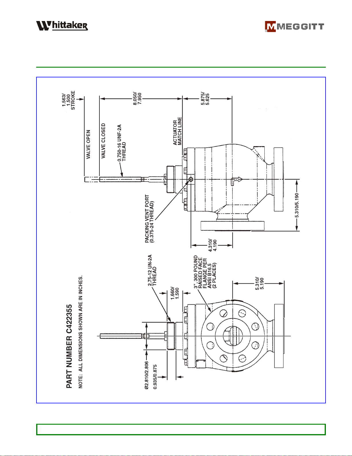
Figure 1. High Recovery Gas Metering Valve (Sheet 1 of 2)
WHITTAKER CONTROLS, INC.
A MEGGITT PLC COMPANY
INSTALLATION AND OPERATION MANUAL
HIGH RECOVERY GAS METERING VALVE
C422355 • C422415
INDUSTRIAL PRODUCTS GROUP Revision 1.0 11/01/2003 Page 10
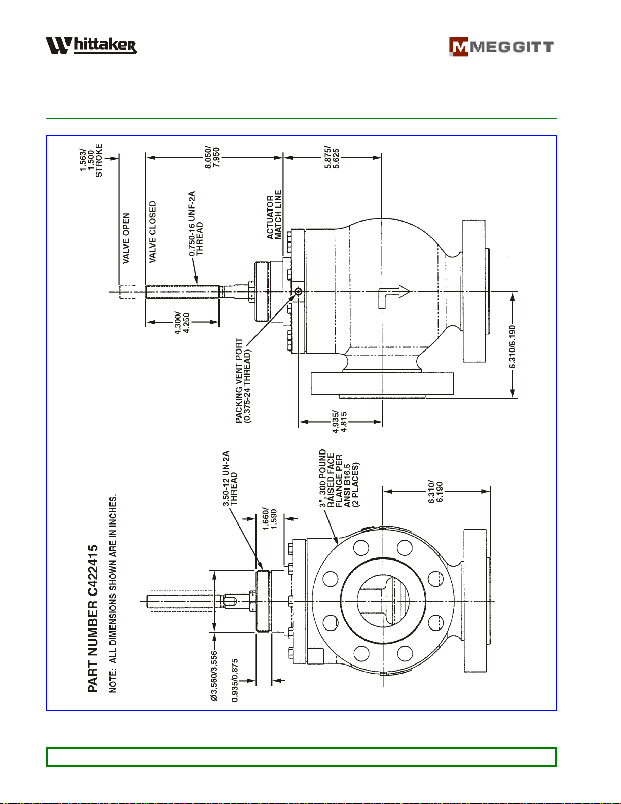
Figure 1. High Recovery Gas Metering Valve (Sheet 2 of 2)

WHITTAKER CONTROLS, INC.
A MEGGITT PLC COMPANY
INSTALLATION AND OPERATION MANUAL
HIGH RECOVERY GAS METERING VALVE
C422355 • C422415
INDUSTRIAL PRODUCTS GROUP Revision 1.0 11/01/2003 Page 11
Table 2. Detailed Specifications
Valve Type ........................................... Gas Flow Control, High Recovery
Service Fluid ......................................... Natural Gas, LPG, Process Gases
Pipe Size
Part Number C422355-[ ] ......................................... 2-inch (50,8 mm)
Part Number C422415-[ ] ......................................... 3-inch (76,2 mm)
Stroke .......................................... 1.500 to 1.563 inches (38,1 to 39,7 mm)
Pressures
Normal Range .................................... 250 to 450 psig (0 to 10 500 kPa)
Proof ..................................................... 750 psig (5 200 kPa)
Temperatures
Ambient .............................................. –20 to 180°F (–29 to 82°C)
Operating ............................................ 370 to 400°F (188 to 204°C)
Fluid (maximum) ................................................. 450°F (232°C)

WHITTAKER CONTROLS, INC.
A MEGGITT PLC COMPANY
INSTALLATION AND OPERATION MANUAL
HIGH RECOVERY GAS METERING VALVE
C422355 • C422415
INDUSTRIAL PRODUCTS GROUP Revision 1.0 11/01/2003 Page 12
INSTALLATION
1. General
This section contains information on installation and interfacing of the valve.
2. Inspection
Prior to installation, visually inspect the valve for shipping damage and general condition. Make sure
that there are no missing parts, loose fittings or fasteners, or any other obvious defects.
3. Actuator Interface
A. The actuator mounting boss external threads are 2.75-12 UNA.
B. The valve shaft external threads are 0.500-20 UNF-2A
4. Gas Inlet and Outlet Ports
A. Part Number C422355-[ ]:
Thegasinletandoutletflangesarenominal2-inch(ANSIB16.5,Class300,raised face)config-
uration. The gaskets and the associated attaching parts must be in accordance the applicable
ANSI standards. All piping interfaces of the high recovery valve are designed to interface with
standard flanges.
B. Part Number C422415-[ ]:
Thegasinletandoutletflangesarenominal3-inch(ANSIB16.5,Class300,raised face)config-
uration. The gaskets and the associated attaching parts must be in accordance the applicable
ANSI standards. All piping interfaces of the high recovery valve are designed to interface with
standard flanges.

WHITTAKER CONTROLS, INC.
A MEGGITT PLC COMPANY
INSTALLATION AND OPERATION MANUAL
HIGH RECOVERY GAS METERING VALVE
C422355 • C422415
INDUSTRIAL PRODUCTS GROUP Revision 1.0 11/01/2003 Page 13
5. Adjustments
A. The associated actuator must be installed, adjusted and calibrated in accordance with the
actuator manufacturer’s documentation.
B. No field adjustments to the valve are required.
This manual suits for next models
1
Other Meggitt Control Unit manuals

Popular Control Unit manuals by other brands


Autotrol
Autotrol Logix 740 Operation manual

Allmatic
Allmatic PROXIMA W quick start guide

H3C
H3C PSR450-12A user manual

Miller-Leaman
Miller-Leaman ATF Series Operation instructions

Festo
Festo DSMI-***-B Series operating instructions

Rockwell Automation
Rockwell Automation Allen-Bradley 1746-HSCE user manual