EC5000
Catalogue
- 1 -
TABLE OF CONTENTS
Chapter 1 Read Below Information Before Use
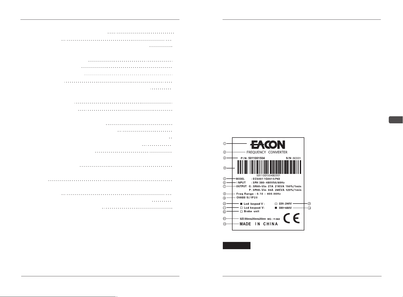
1.1 Delivery Inspection
1.2 Transport
1.3 Storage
1.4 Considerations for Choices of AC Drives
Chapter 2 Installation and Wire Layout
2.1 Installation Environment
2.2 Installation Conditions
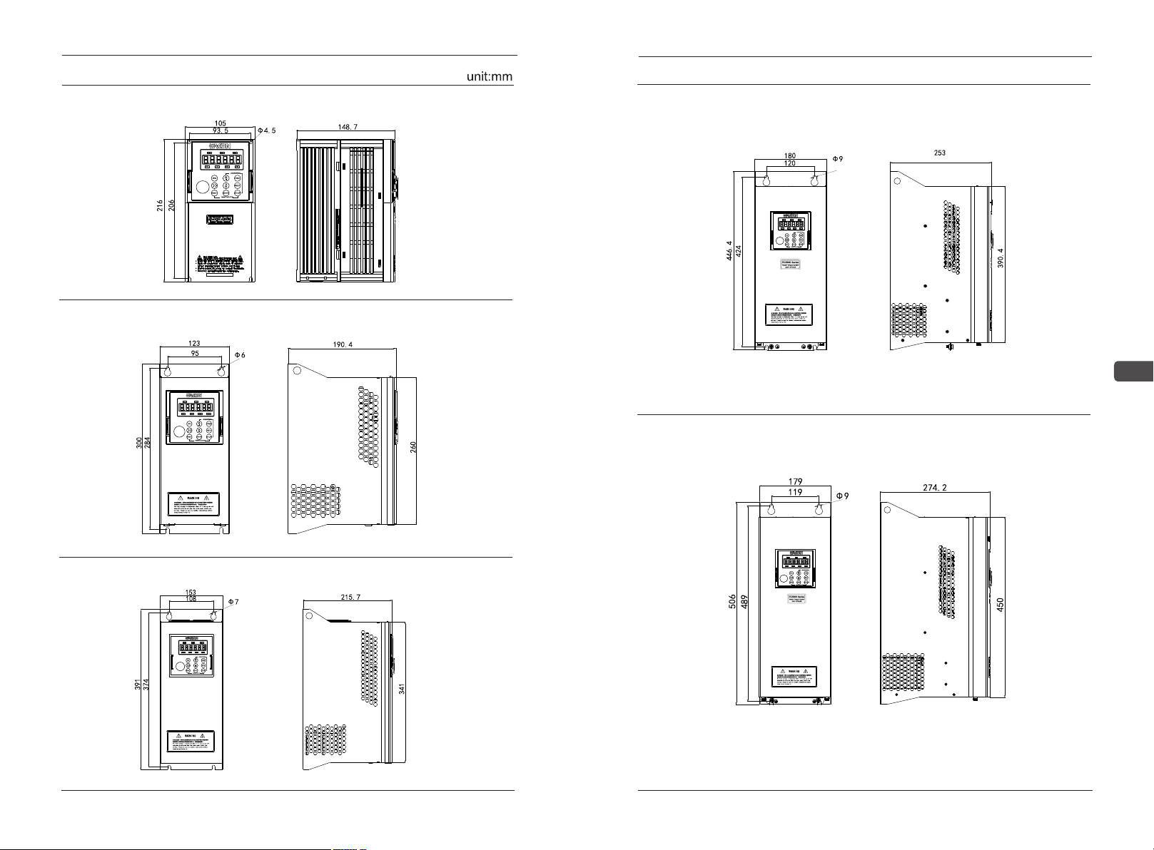
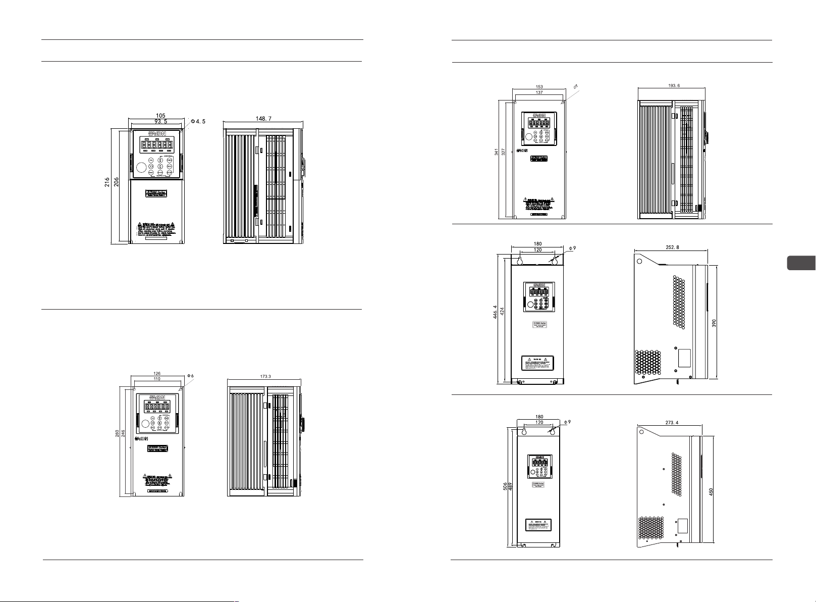
2.3 Installation Dimension of AC Drive
2.3.1 200V Installation Dimension of AC Drive
2.3.2 400V Installation Dimension of AC Drive
2.4 Instruction for Wire Layout
2.4.1 Basic Wire Layout
2.4.2 System Wiring Diagram
2.4.3 Main Circuit Terminal Connection
2.4.4 Control Terminal Connection
Chapter 3 Operation and Inspection
3.1 Check and Test before Operation
3.2 Running Way
3.3 Test Run
Chapter 4 Operation Keypad Panel
4.1Appearance & Operation Procedure of LED Keypad Panel
4.1.1 Appearance of LED Keypad Panel
4.1.2Operation Procedure of LED Keypad Panel
4.2 Appearance & Operation Procedure of LCD Keypad Panel
4.2.1 LCD Keyboard Panel Appearance
4.2.2 Operation Procedure of LCD Keypad Panel
Chapter 5 Description of Functional Parameter
5.1 Function Parameter List
5.2 Detailed Description of Functional Parameters
Chapter 6 MODBUS Communication Protocol
6.1 Communication Data Structure
6.2 Data Format Frame
6.2.1 Communication Address
Warning!
Notice!
1.Please do not test the voltage resistance of the interior components
of the driver, as the semiconductor of the driver is easy to be punctured
and damaged by high voltage.
2. The circuit board of the driver has CMOS IC which is extremely
easy to be damaged by static electricity, thus please do not touch the
circuit board with your hand before taking anti-static electricity measures.
3.Even if the motor is inactive, the main loop terminal of the driver
may still have dangerous high voltage.
4.Only the qualified motor professionals can install the driver, lay the
wire, repair and maintain the driver.
1.When certain functions of the driver are set, the motor may
immediately start after the power input.
2.Please choose a safe place to install the AC drive to avoid the high
temperature, direct sunlight, humidity and splash of water drops.
3.Please prevent the children or irrelevant people against being
close to the AC drive.
4.The AC drive can only be used in the places recognized by our
company, and the usage in an environment not recognized by our
company may lead to fire, gas explosion or electrification.
5.When the wire between the AC drive and the motor is too long, the
inter-layer insulation of the motor may be damaged, please use the
special AC motor for AC drive, or add a reactor between the driver and the
motor to prevent the AC drive from being burned due to the damage of
insulation.
6.he rated voltage of the power system for the driver can't be higher
than ±15% of the rated voltage of product, and the current can't be over
5000A RMS (The current of 40HP (30kW) type or above can't be over
10000A RMS).
1
2
3
4
6
6
7
7
11
16
16
21
26
27
31
31
32
33
33
34
35
36
36
40
53
97
98
96