Megmeet Dex CM3000 User manual

Dex Fully-digital Converter CO /MAG/MIG
2
Multi-function Welding Power Source
Dex CM3000
Dex PM3000
User Manual

Full-Digital Control CO2/MAG/MIG Multi-FunctionWelding Machine
User Manual
Model:Dex CM/PM 3000
Version:V1.0
Code :R33010360
Shenzhen Megmeet Electric Co., Ltd(Megmeet) provides customers with all-around technical supports,
including but not limited to opening CAN communications, welding process database software upgrading,
and after-sales service etc. Users can contact a nearby representative office or Customer Service Center of
Megmeet, or directly contact Megmeet Headquarter.
All rights reserved by Shenzhen Megmeet Electric Co., Ltd.
The contents are subject to change without further notice.
Shenzhen Megmeet Electric Co., Ltd.
Address: 5thFloor,Block B Unisplendour Information Harbor,LangshanRoad,shenzhen,518057,China
Website: www.megmeet.com
Customer servicehotline:4006662163
E-mail:Welder.4S@megmeet.com

Preface
Thank you for choosing the full-digital inverter CO2/MAG/MIG multi-function welding power
sourcemanufactured by Megmeet (hereinafter referred to as “welder”). This manual presents precautions on
installation and wire connection, parameters setting, troubleshooting and daily maintenance.
Please read this User Manual carefully before installation to ensure correct installation and operation of
the welder. Please keep it properly and deliver to the user.
Megmeet will consistently carry out product development and innovation. If the actual product is not in
conformity with the content, parameters, or diagrams in this document, the actual product shall prevail. This
document may subject to change without notice and Megmeetreserves the right of final interpretation of this
document.

Safety precautions
Safety Definition
In order to use the welding power source safely and correctly to prevent harm to you or others and other
damages, this manual uses various types of warning labels.Please be sure to follow theinstructions
carefully.
The following signs are classified according to the degree of danger or damage:
Danger
Please follow the instructions,otherwise it may cause death or serious injury.
Note
!
Please follow the instructions, otherwise it may cause moderate or minor injuries or
damage to property.
Before handling the welder, the input power supply of distribution box should be cut off.
Make sure that the machine casing has been firmly installedbefore handling of the welder.
Please install it on a noncombustible object, otherwise it may lead to fire hazard.
Do not put any combustible material around the welder, otherwise it may lead to fire hazard.
Do not install it in an environment containing explosive gas, otherwise it may lead to explosion hazard.
Wiring operation should be performed by professional qualified personnel, otherwise it may lead to electric shock
hazard.
Do not do wiring until confirming that the input power has been fully disconnected, otherwise it may lead to electric
shock hazard.
The machine casing should be covered up before power on, otherwise it may lead to electric shock hazard.
Do not touch the terminal with hands when the machine is powered on, otherwise it may lead to electric shock hazard.
Do not operate the welder with wet hands,otherwise it may lead to electric shock hazard.
Installation Precautions
DANGER
Wiring operation should be performed by professional qualified personnel, otherwise it may lead to electric
shock hazard.
Do not do wiring until confirming that the input power has been fully disconnected, otherwise it may lead to
electric shock hazard.
The machine casing should be covered up before power on, otherwise it may lead to electric shock hazard.
Do not touch the terminal with hands when the machine is powered on, otherwise it may lead to electric shock
hazard.
Do not operate the welder with wethands, otherwise it may lead to electric shock hazard.
Part replacement should be performed by professional personnel. It is forbidden to leave the wire head or metal
objects in the machine, otherwise it may lead to fire hazard.
After replacing the control panel, the parameters must be set correctly before running, otherwise it may cause
damage to property.
Use the exposed part of the cable nose for wiring. Wrap it up with insulating tape, otherwise it may lead to
electric shock hazard.
Maint
enance operation can only be carried out 5 minutes after disconnecting the power supply. At this time, the
welding power indicator light will be completely extinguished. Confirm that the positive and negative bus
voltage should be under 36V, otherwise it may lead to electric shock hazard.
It is prohibited to open the side cover of the machine by hand while storing or using the machine outdoorson
rainy days.
ATTENTION
!
Avoid the operation panel from falling off during handling process, otherwise it may lead to the risk of injury or
damage to property.
Fix the wheels firmlywhile handling the welder with a forklift truck.
The welding machinesShould be installed at a place which can support its weight, otherwise it may lead to the
risk of injury or damage to property if it falls off.
It is strictly forbidden to install the machine at a place with water pipes or others which may produce water
splashing; otherwise it may cause damage to property.
Don't put screws, gaskets and metal bars into the welder, otherwise it may lead to fire hazard or damage to
property.
If the welding machineis damaged or the components are not complete, the machine should not be installed and
used, otherwise it may lead to fire hazard or damage.
The quick plug of the main circuit terminal should be rotated to connect tightly, otherwise it maylead to damage
to property.
SafetyPrecautions
DANGER
In order to ensure safety, welding operation should be performed by personnel with safe operation knowledge
and welding skills.
Please do not use welding machinefor the purposes other than welding.
Installation, commissioning and maintenance of welding machinemust be carried out by professionals.
Operators who use a cardiac pacemaker shall not get close to the welder and welding operation site without the
permission of doctor.
Do not touch live parts, otherwise it may lead to electric shock hazard.
Do not use cable with insufficientsection area, exposed conductor or any damage.
Do not demount the shell while using the machine.
Please use intact insulating gloves with excellent insulating property.
Please take safety measuresfor high altitude operation.
Please turn off the power of welding machineand distribution box when it is not in use.
When weld in a narrow or confined space, please accept the supervision from inspectors and ensure sufficient
ventilation or use breathing apparatus; otherwise, the operator may get asphyxiated due to lack of oxygen.
Welding process will produce harmful fumes and gases. Therefore, please ensure adequate ventilation or use
breathing apparatus, otherwise, it will endanger your health.
Please do not weld pressure vessels such as pipes filled with gas or sealed tank.
Please do not keep thermal parts close to combustible materials.
Please do not weld around combustible materials.
Please put fire extinguishers around welding operation place.
Fix the gas cylinder with special brackets, otherwise the gas cylinder may topple over which will lead to
personal injury.
Please do not make the electrode contact the gas cylinder.
Please correctly use pressure-relief valve as required.
Disassembly and maintenance of pressure reducing valve should be performed by professionals.
Please do not contact the fan, wire feeding machine and other rotating parts, otherwise it may cause personal
injury.
While performing welding or supervising welding, please use protective equipment with sufficient shading
performance to prevent the arc from damaging eyes or skin.
Please use leather protective gloves for welding, long-sleeved clothes, welding spats, apron, glasses and other
protective equipment to prevent damage caused by arc, splash and welding slag etc.
Set protective barriers around the welding site to prevent the arc from hurting others.
Please use sound insulation instruments to prevent noise hazard.
ATTENTION
!
It is forbidden to use this welding machine on operations other than welding.
Please do not place heavy objects on the welder.
Please do not block the ventilation opening of welding machine.
Please place it in a place where spatter and other metal objects will not fall inside the welder.
Please keep the machine more than 30cm away from wall or other welders.
To prevent the wind from blowing the arc directly, please use a screen for shielding.
Please fix the wheels and avoid welding machine sliding.
In order to prevent electromagnetic hazard, perform electromagnetic shielding for cable and welding operation
site.
The inclination angle of welding machine installation plane should be less than 15°to prevent toppling of
machine.
Protection grade of welding machines IP23S. The operation environment requirements are as follows:
Operating temperature range: -10℃~+40℃;
Transportation and storage temperature range: -40℃~+70℃
Operating humidity range: Not exceed 75%RH at 40℃; not exceed 95%RH at 20℃.
Altitude shall not be higher than 2,000m.

Operating environment should be free ofobvious mechanical vibration or mechanical shock.
Inclination angle of welder shall not be more than 15 °.
Dust, metal dust and corrosive gases in ambient air shall not exceed the normal content
Avoid the
welding machine
exposed to rain or rainwater invasion to fan.
Precautions for Scrapping
Please note at welding machine scrapping that:
An explosion may occur during incineration of the electrolytic capacitor on the main circuit and
PCB.
Plastic parts such as front panel will generate toxic fumes during incineration.
Please handle the scrapped machine as industrial waste.

Contents
Chapter I Product Overview ................................................................................................................. 1
1.1 Brief Introduction ................................................................................................................... 1
1.2 System Composition............................................................................................................... 1
Chapter II Wiring Installation.............................................................................................................. 2
2.1 Unpacking ............................................................................................................................. 2
2.2 Installation Requirements....................................................................................................... 2
2.3 Precautions for Handling........................................................................................................ 2
2.4 Serial Number of Machine ..................................................................................................... 2
2.5 Machine Installation and Electrical Connection...................................................................... 2
2.5.1 380VAC Power Input Cable...................................................................................... 3
2.5.2 Welding Torch Connection ........................................................................................ 3
2.5.3 Welding Cable (Ground Wire) Connection beside the Workpiece............................... 3
2.5.4 Wire FeedingRollerInstallation.................................................................................. 4
2.5.5 Wire SpoolInstallation............................................................................................... 5
2.5.6 Regulation on Pressure Adjusting Rod....................................................................... 5
2.5.7 Air Supply System Connection.................................................................................. 5
Chapter III Dex CM3000Function Description and Operation ........................................................... 6
3.1 Front Panel ............................................................................................................................ 6
3.2 Buttons and Knobs................................................................................................................. 6
3.3 Wire Inching.......................................................................................................................... 6
3.4 Gas Detection........................................................................................................................ 6
3.5 Synergic/Separate.................................................................................................................. 7
3.6 Arc Dynamics........................................................................................................................ 7
3.7 Internal Menu ........................................................................................................................ 8
Chapter IV Dex PM3000Function Description and Operation...........................................................17
4.1 FrontPanel ............................................................................................................................17
4.2 Wire Inching.........................................................................................................................18
4.3 Gas Detection.......................................................................................................................18
4.4 Synergic /Separation.............................................................................................................18
4.5 Arc Dynamics.......................................................................................................................19
4.6 Arc Starting Parameter..........................................................................................................19
4.7 Arc Ending Parameter...........................................................................................................20
4.8 Welding Control ...................................................................................................................20
4.9 Storage and Invocation..........................................................................................................23
4.10 InternalMenu ........................................................................................................................23
Chapter V Troubleshooting..................................................................................................................33
5.1 Welding Machine FaultIndication.........................................................................................33
5.2 Fault Codes and Solutions.....................................................................................................33
Chapter VI Maintenance ......................................................................................................................35
6.1 Daily Inspection....................................................................................................................35
6.2 Periodic Inspection ...............................................................................................................36
6.3 After-Sales Services..............................................................................................................37
Annex I Technical Specifications..........................................................................................................38
Annex II Electrical Connection Diagram.............................................................................................39
Annex III System Configuration Table................................................................................................40
Annex IV Structural Detail Drawing ...................................................................................................42

Chapter I Product Overview 1
Full-Digital Control CO2/MAG/MIG Multi-FunctionWelding Machine
ChapterI Product Overview
1.1 Brief Introduction
Dex CM3000 and Dex PM3000 is a full digital control multi-functional integrated welding machine, It
applies to welding of car seats, motorcycles, sheet metal and medium thin plates, as well as backing (root
welding)weld of medium thick plates, etc.
With the functions of , MAG, MIG gas shielded welding and manual arc welding.
Special welding control method can be customized for customers.
Three-electrical level technique with an inverting frequency up to 180KHz is adopted.
Dex CM3000 can be used for welding with a variety of welding materials including carbon steel,
stainless steel, and galvanized sheet etc.
Dex PM3000 can be used for welding for carbon steel, stainless steel , pure aluminum ,aluminum and
other welding materials.
1.2 System Composition
Welding machine system is as shown in Fig. 1-1.
Fig. 1- 1System Composition

2 Chapter II Wiring Installation
Full-Digital Control CO2/MAG/MIG Multi-FunctionWelding Machine
ChapterII Wiring Installation
The chapter presented the installation requirements of welding machine, as well as the operation steps and
precautions associated with the installation.
2.1 Unpacking
The machine is packedwitha specially designed& durable package.
1. Please confirm whether the outer package of the product is intact.
2. After unpacking, please confirm whether the welder accessories, installation and operating instructions
are intact and whether the model is consistent with the order.
3. Packaging materials can be recycled.
2.2 Installation Requirements
Environmental requirements
The following items should be noted while selecting the installation environment:
1. It should be installed at a place with good ventilation and the vibration should be less than 5.9 m/s
(0.6 g).
2. Avoid installing the machine at a place with much dust and metal powder.
3. It is strictly prohibited to install the machine at a place with corrosive or explosive gas.
4. The environment temperature should be within the range of -10℃~+40℃. When the temperature
exceeds 40 ℃, external forced cooling or derating use is required.
5. The humidity should be lower than 95%, and should be free of water condensation. Pay attention to
wind prevention at the welding site.
6. Use a windshield or else if necessary, otherwise the welding process will be affected.
7. Prevent the machine fromexposure to rain and direct sunlight.
8. Please consult and confirm in advance if there are any special installation requirements.
9. Installation space requirements: It is recommended to place the welding power according to the
reserved space as specified in Table 2-1.
Table2- 1Reserved Space for Installation of Welding Power
Front Top Left Right Back
Reserved space ≥20cm ≥40cm ≥60cm ≥20cm ≥20cm
2.3 Precautions for Handling
Before handling the welding power supply, make sure to cut off the input power of the distribution box and
remove the wire inside the welder.
2.4 Serial Number of Machine
The serial number of the machine is unique and is marked on the nameplate. It is very importantinformation
for maintenance and spare parts ordering.
2.5 Machine Installation and Electrical Connection
Safety warning
1. Wiring connection should be performed by qualified and professional electrical operator.
2. Electrical connection should be carriedon when the distribution box switch is disconnected and safety can be ensured.
Chapter II Wiring Installation 3
Full-Digital Control CO2/MAG/MIG Multi-FunctionWelding Machine
3. Please use specified cable.
4. Do not touch the machine with wet hands.
5. Please do not put heavy objects on the cable.
6. Tap-water pipe and the building body steel bar may not be fully grounded. Please do not use it to connect the safety
ground wire.
7. Please connect this welding power source with the matching or specified welding gun and gas meter, otherwise it will
affect welding performance and welding quality.
8. Install a leakage protector when the workplace is wet and operating on iron plates or iron frames.
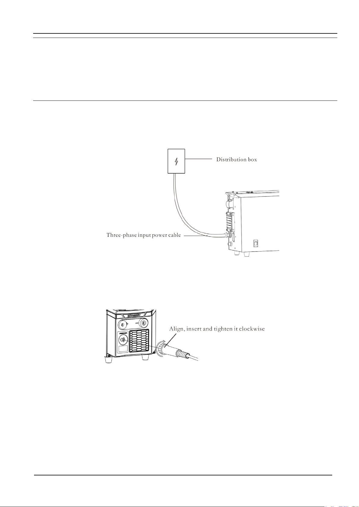
2.5.1 380VAC Power Input Cable
This welder is equipped with 3Mpower supply cable (plug excluded). Please arrange a professional
electrician to connect the input cable of the other end to the output terminal of the distribution box switch.
The selection of AC input cable shall strictly followAnnex I Technical Specifications.
Fig.2- 1380VAC Power Input Side Schematic Diagram
2.5.2 Welding Torch Connection
Align and insertthe welding torchto the socket and tighten withclockwise as shown in Fig. 2-2.
Fig.2- 2 Welding Torch Connection Schematic Diagram
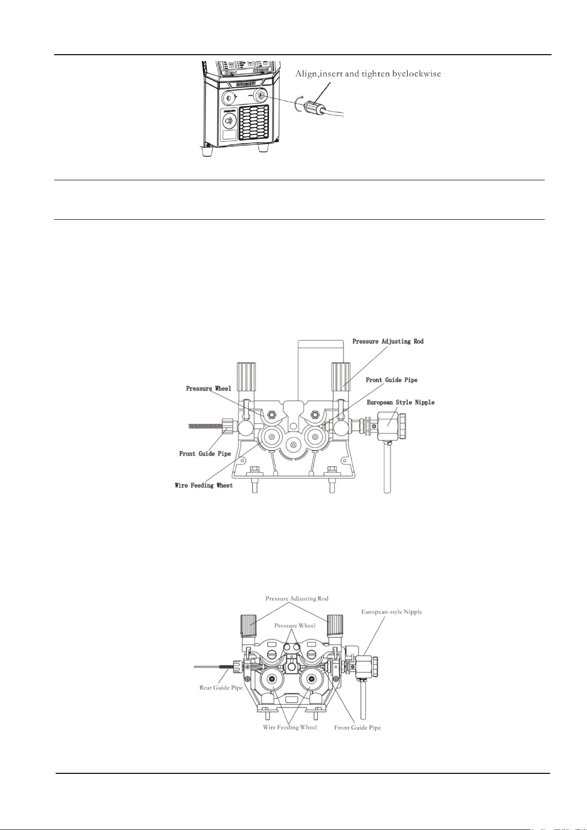
2.5.3 Welding Cable (Ground Wire) Connection beside the Work-piece
Align and insert the ground cable to the socket and tighten it clockwise, as shown in Fig. 2-3. Fasten the
other end to the work-piece. Keep the contact area on the work-piece as large as possible. The work-piece
surface should be no dirt or painting;otherwise the wire clamp will be burnt.
4 Chapter II Wiring Installation
Full-Digital Control CO2/MAG/MIG Multi-FunctionWelding Machine
Fig.2- 3GroundCable Connection SchematicDiagram
Attention
In order to ensure the welding performance and using life of the ground wire, it is suggested that the cross section of the
ground wire should be above 25mm2.
2.5.4 Wire FeedingRollerInstallation
Dex CM3000
Remove the black plastic knob from wirefeedrollerby counter-clockwisedirection. Install the wire-feeding
roller according to operation requirements. Afterwire feeding roller installation, tighten black plastic knob
by clockwise. Wire diameter is marked on the wire feed roller. The marked wire diameter is
correspondingslotdiameter of wire feeding roller.
Fig.2- 4Dex CM3000Schematic Diagram of Wire Driving Motor
Dex PM3000
Remove the screwfrom wire feeding rollerby counter-clockwisedirection. Install the wire-feeding roller
according to operation requirements. After wire feeding roller installation, tighten blackthe screw by
clockwise. Wire diameter is marked on the wire feed roller. The marked wire diameter is
correspondingslotdiameter of wire feeding roller.
Fig.2- 5Dex PM3000Schematic Diagram of Wire Driving Motor
Chapter II Wiring Installation 5
Full-Digital Control CO2/MAG/MIG Multi-FunctionWelding Machine
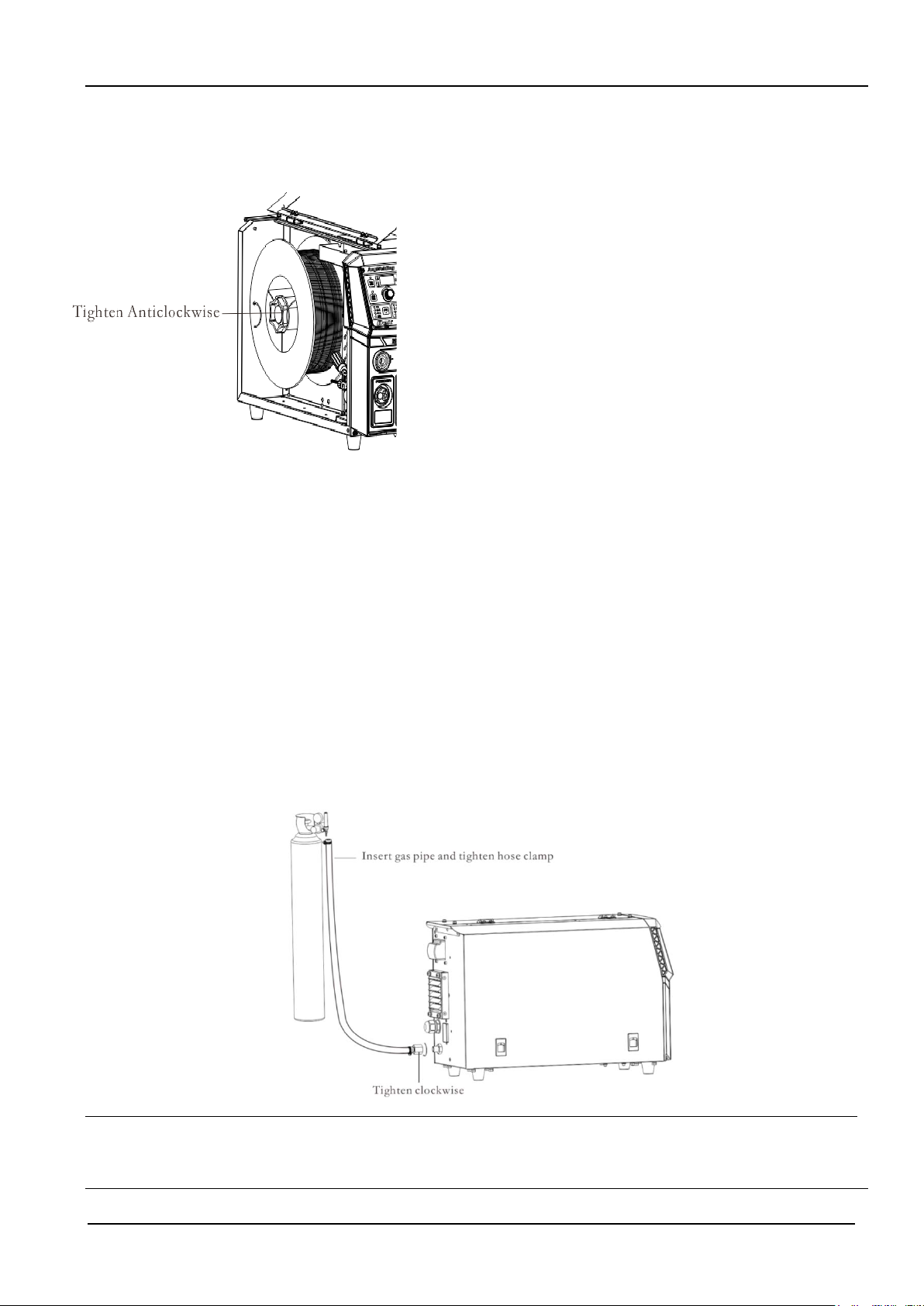
2.5.5 Wire SpoolInstallation
1. Rotate the end cover of the coil shaft by clockwise direction to loosen
the end cover.
2. Push in the wire coil;Align the slot of wire coil so that the slot can
successfully enter the terminal of disc shaft. In addition, pay attention to
the rotation direction of wire coil to avoid reverse direction of wire
feeding.
3. Rotate shaft end cover by anti- clockwise, and lock the wire
feedingcoil.
4. Select and install the suitable wire feed rollers.
5. Extract the wirehead from the wire coil, cut off the bending part. The
cut welding wirecould notfall into the machine. Straighten the welding
wire about 20cm and check whether there are anysharp corners at the end.
The sharp corners should be filed to avoid the wire feeding tube and
current contact nozzle being damaged.
6. Pull outa section of welding wire. Gothrough the slot and leading wire
tube to the welding torch from the rear guide wire. And clamp the wire
feed roll.
7. Hold the manual wire feeding on the machine panel, then deliver the
welding wire to the torch end. In case of slipping or wire flattening
during wire feeding process, please adjust through pressure adjustment
bar..
2.5.6 Regulation on Pressure Adjusting Rod
Regulate the black knob of pressure adjusting rod to make the welding wire equally pass through the wire
feeding liner and contact nozzle to the end of welding torch.Apply certain resistance to the wire reel after
welding wire delivery to preventwire feed roll slipping. If the pressure bar is adjusted too tight, the welding
wire will be flattened, the clad layer on the wire surface will be destroyed, and the service life of feeding
roller will be reduced, which will lead more resistance ,then worse welding instability. Please adjust the
pressing force reasonably.
2.5.7 Air Supply System Connection
Connect the gaspipe to the back panel of the machine, and tighten the hose clamp of gaspipe. Connect the
other end to the gas regulator, and tighten the hose clamp, as shown in Fig. 2-6.
Fig.2- 6Schematic Diagram of Gas Pipe Connection
Attentions:
1. If any protective gas containing CO2is used, please use CO2heating pressure reducing valve.
2. The gas pipes on welding machine and gas regulator should be firmlyfixed;otherwise there will be air leakage.
6 Chapter III Dex CM3000
Full-Digital Control CO2/MAG/MIG Multi-FunctionWelding Machine
ChapterIII Dex CM3000
Function Description and Operation
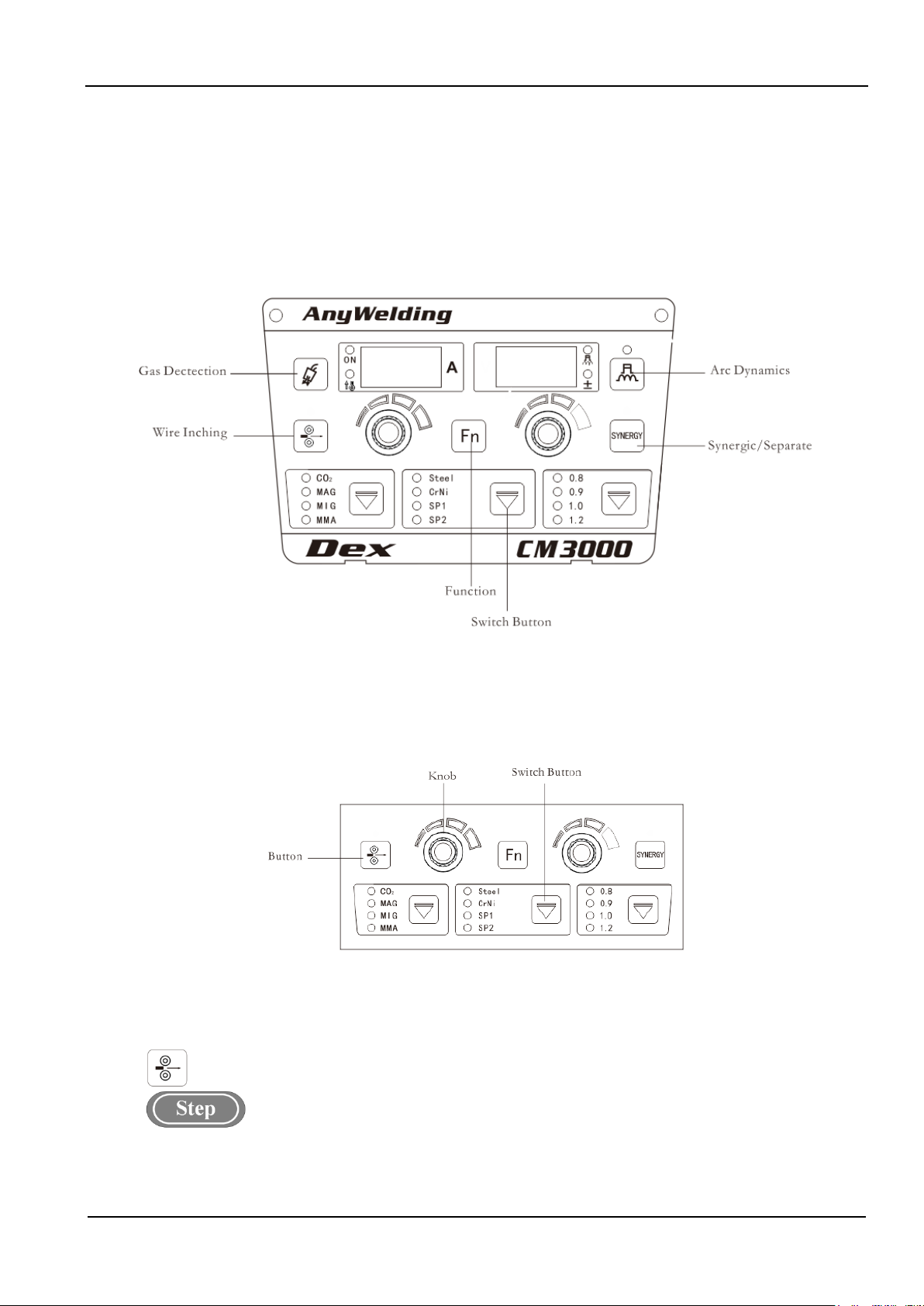
3.1 Front Panel
Function description offront panel is as shown in Fig. 3-1.
Fig.3- 1 Function Description of Front Panel
3.2 Buttons and Knobs
Button operation is divided into short-press (Touch) and long-press(Hold). Long-press must be hold more
than 3 seconds until the system responses.
Fig.3- 2 Buttons and Knobs
3.3 Wire Inching
Wire is sent to tip of welding torch by manual under non-welding condition.
1. Press on "Wire Inching" key,the LED light will be on.
The wire inching speed is rated wire feeding speed. The maximumwire inching speed is 8 meters/min.
2. Release the function button;LED light is off, then wire feeding stops.
Chapter III Dex CM3000 7
Full-Digital Control CO2/MAG/MIG Multi-FunctionWelding Machine
3.4 Gas Detection
Check whether there is gas or not, and gas flow rate.
1. Touch “Gas Detection” button, LED light will be on.
Gas starts to flow. Then gas flow ratecan be checked. Gas detection function will be shut downautomatically
30 second later.
2. Press thebutton again,light LED will be off and gas detection stopped.
3.5 Synergic/Separate
Under the synergic mode,the LED light will lasts on.
Short-Pressingthisbutton, theright nixie tubewill show switch between synergic correction value and
synergic voltage
Synergic:Welding voltage varies along with the changes of current. Standard synergic voltage modified
value is 0. Voltage modification range is ±30.
The rated voltage relationship as below:
The rated welding voltage=the synergic voltage+the voltage modification range %)×(thesynergic voltage)
Separation:Current& voltage is adjusted separately.
1. Long-pressing "Function" key more than 3seconds, then enter into internal menu.
2. Turn the left knob and regulate to FC3. (Synergic/Separation Switch)
3. Turn the right knob toswitch Synergic or Separation mode. The default value is OFF. (Synergic)
Attentions
Under the Synergic function, the voltage normal point should be set to zero. Current and voltage matching relationship
specified by the manufacturer is realized under normal point.
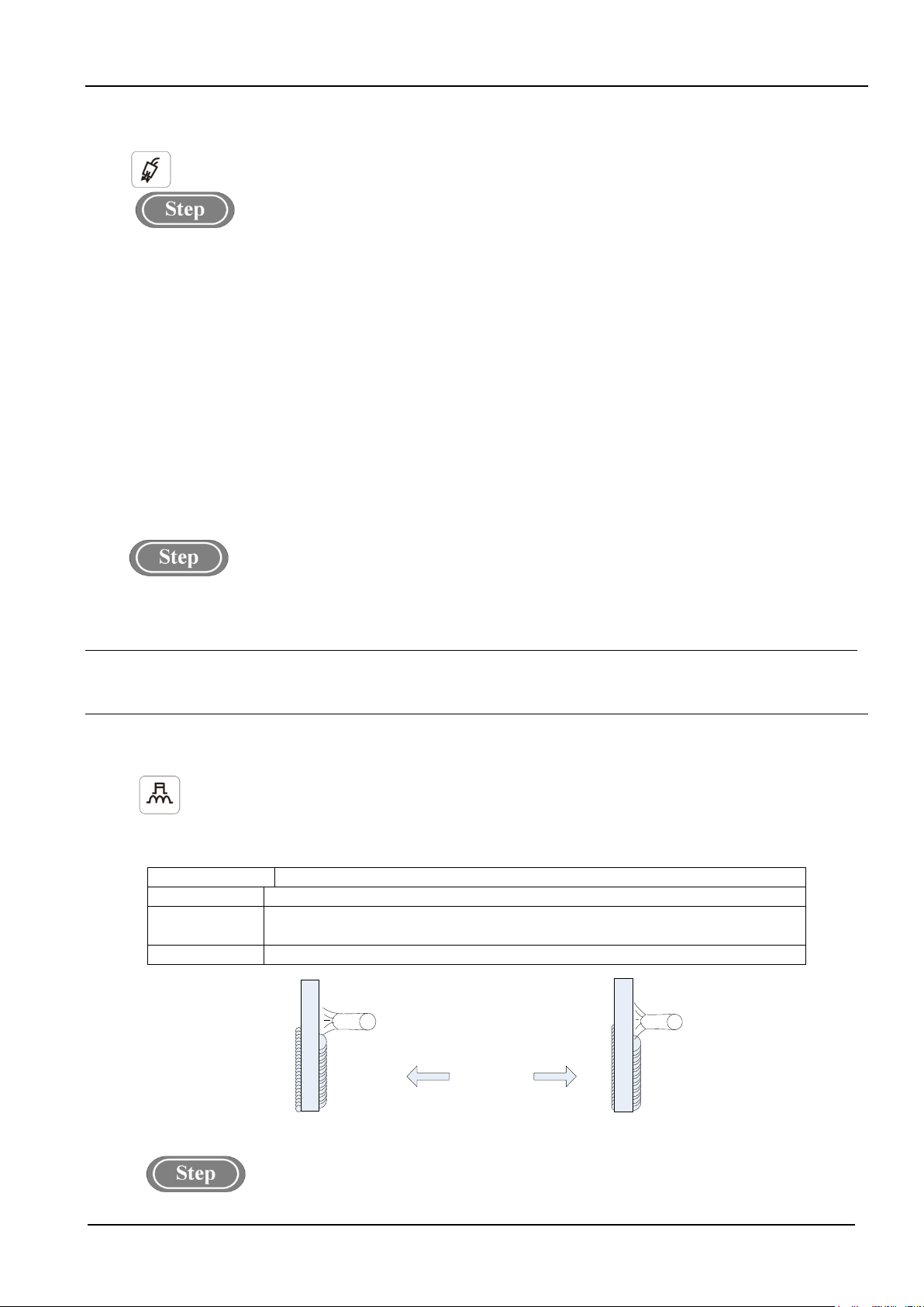
3.6 Arc Dynamics
Arc dynamicsis to adjust hardness of arc.
Harden the arc by adjusting in positive direction and soften arc by negative direction
Arc dynamics are described as shown in Table 3-1 andFig.3-3.
Table3- 1Arc Dynamics Description
Arc Dynamics
Functions
0 (Default value) Universal use, Default value
0~9 (hard arc) Deep and easy penetrated. Suitable for full position welding and high speed welding. The arc
stability also could be ensured under extended cable
0~-9 (soft arc)
Shallow and not easy to be fully penetrated. The values are suitable for welding of thin plate.
Positive direction Negative direction
0
Fig.3- 3 Schematic diagram of electric arc dynamics
1. Touch the “Arc Dynamics”button, LED will be on, then arc dynamicsfunction will be on.

8 Chapter III Dex CM3000
Full-Digital Control CO2/MAG/MIG Multi-FunctionWelding Machine
2. Under this circumstance, the LED will be onsimultaneously. Rotate the knob to adjust the range
of arc dynamics -9~0~+9.
3.7 InternalMenu
The button is to enter into internal menu.
1. Long pressing "Function" key more than 3 seconds to enter into internal menu.Short-Pressing the
button to exit the internal menu.
2. Under internal menu settings, turn the left knob and adjust the left nixie tube. Turn theright panel knob
and adjust theright nixie tube.
3. Once setting completed, short-press to exit internal menu.
Detailed information of internal menu is as shown in Table 3-2.
Table3- 2Internal Menu
Function
Code
Function Name and Meaning
Adjusting
Range
Step Length Default Value
F01 Restore factory settings
F10 Slow Wire Feeding Speed 1.4~18m/min. 0.1 m/min. 2.4m/min.
F11 Pre-Gas Time 0~25s 0.1s 0s
F12 Soft-Starting Time 0.001~0.999s 0.001s Automatic Match
F13 Transition Time of Wire Feeding Speed 0.01~9.99s 0.01s 0.1s
F14 Post-gasTime 0~25s 0.1s 1s
F15 ManualWire Feeding Speed 1.4~8 m/min. 0.1 m/min. AutomaticMatch
F20 DC Burn-Back Voltage 12~30V 0.1V 12V
F21 DC Burn-Back Time 0.00~1.00s 0.01s Automatic Match
F22 DC Chopping Time 0.00~1.00s 0.01s 0.24s
F23 Fast Rising Slope of DC Welding
Short-Circuit Current 1~300 1 Automatic Match
F24 Fast rising Amplitude of DC Welding
Short-Circuit Current
0~500A 1A Automatic Match
F25 Welding control 0~3
0FF(2 steps)
F26
Percentage of wire feeding speed in arc
starting stage 1~200 0FF(100)
F27 Synergic voltage corrected value in arc
starting stage
-30%~+30%
0
F28 Arc dynamics in arc starting stage -9~+9
0
F29 Arc starting time 0~10 seconds
0FF(0)
F50 Arc startingTime 0~10s 0.1s Temporarily not
Open
F51 Arc endingTime 0~10s 0.1s Temporarily not
Open
F52 MMAArc starting Current 0~400A 1A 300A
F53 MMAHot-StartingCurrent 0~60A 1A 50A
F54 MMAThrusting Current 0~50A 1A 30A
F55 DC Welding Energy Control 0~200 1 0
F2A
Percentage of wire feeding speed in arc
ending stage 1~200 0FF(100)
F2B Synergic voltage corrected value in arc
ending stage
-30%~+30%
0
F2C Arc dynamics in arc ending stage -9~+9
0
F2D Arc ending time 0~10seconds
0FF(0)

Chapter III Dex CM3000 9
Full-Digital Control CO2/MAG/MIG Multi-FunctionWelding Machine
F2E Spot welding time 0~10seconds
0FF(0)
FB0 Software Version Query
FB1 Error Record 0~199
FB2 Machine Model Query
FC0 Switch of Rapid Welding
Mode/Standard Welding Mode
OFF(Standard
Welding Mode)
FC2 MMASelection Switch
OFF
FC3 Synergic/Separation Switch
OFF (Synergic)
Slow Wire Feeding Speed(F10)
Check wire-feedingspeedbefore arc starting.
1. Long press "Function" key for more than 3 seconds to enter into internal menu; turn the left knob to
F10.
2. Turn right knob to adjust the F10 parameters (shown in table 3-3).
3. Short-press "Function" key to exit internal menu and F10 parameter settings is completed.
Table3- 3Parameter Table of Slow Wire Feeding Speed
Function Code Unit Adjusting Range Step Length Default Value
F10 m/min. 1.4~18 m/min. 0.1 m/min. 2.4 m/min.
Pre-Gas Time(F11)
Gas delivery time beforearc starting.
1. Long press "Function" key more than 3 seconds to enter into internal menu, turn the left knob to F11.
2. Turn the right knob to adjust parameters under F11 (shown in table 3-4).
3. Short press "Function" key to exit internal menu, F11 parameter settings is completed.
Table3- 4Parameter Table of Pre-gasTime
Function Code Unit Adjusting Range Step Length Default Value
F11 s 0~25s 0.1s 0.2s
Soft-startingTime (F12)
Adjust the time on slow wire feeding or arc starting wire feedingspeed.
1. Long press "Function" key for 3 seconds to enter interior menu, turn the panel knob and adjust the
knob to F12.
2. Turn the right knob to adjust F12 parameters(shown in table 3-5)
3. Short press “Function” key to exit from internal menuand F12 parameter settings is completed.
Table3- 5Parameter Table of Hot-start Time
Function Code Unit Adjusting Range Step Length Default Value
F12 s 0.01~0.999S 0.001S Automatic Matching
Transition Time of Wire Feeding Speed (F13)
Transition time from arcing feed wire speed to the given welding wire feeding speed or the transition time
from given wire feeding speed to arc ending wire feeding speed.
1. Long press "Function" key for 3 seconds to enter interior menu, turn the left panel knob and adjust the
knob to F13.
10 Chapter III Dex CM3000
Full-Digital Control CO2/MAG/MIG Multi-FunctionWelding Machine
2. Turn the knob on the right panel to adjust F13 parameters (shown in table 3-6).
3. Shortpress “Function” key to exit from internal menu and F13 parameter settings is completed.
Table3- 6Parameter Table of Transition Time of Wire Feeding Speed
Function Code Unit Adjusting Range Step Length Default Value
F13 s 0.01~9.99S 0.01s 0.1s
Post-gas Time (F14)
Post-gas time after arc ending.
1. Enter into internalmenu by holding on “Function” key 3 seconds; turn the panel knob to F14.
2. Adjust the F14parameters, press“Function” again, F14 parameter settings is completed.
Table3-7Parameter Table of post-gas Time
Function Code Unit Adjusting Range Step Length Default Value
F14 s 0~25s 0.1s 1s
Wire InchingSpeed (F15)
The speed in which the wire is sent to the tip of the torch under the non-welding condition.
1. Enter into internal menu; turn the panel knob to F15. Press “Function” key, then the right LCD will be
twinkled.
2. Adjust F15 parameters by rotating the right knob (Table 3-8).
3. Press “Function”key againto exit from internal menu, F15 parameter settings is completed.
Table3-8 Parameter Table ofManual Wire Feeding Speed
Function Code Unit Adjusting Range Step Length Default Value
F15 m/min. 1.4~8 m/min. 0.1 m/min. Automatic
Matching
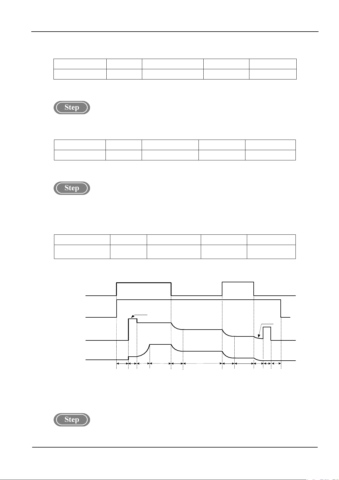
Logicdiagram of DC parameters.
As shown in the figure3-4.
Welding Torch
Switch
Gas Delivery
Welding
Voltage
Wire Feeding
Speed
(Welding Current)
Preflow
Gas
No-Load
Voltage
Arcing
Process Welding Process
DC
Burn-
Back
Time
OFF
ON
OFF
ON
OFF
Arc-
Retreating
Process
Soft-
Start
Time
Transition
Time of Wire
Feeding Speed
Slow
Wire
feeding
DC
Chopping
Time
Burn-Back
Voltage
Transition
Time of Wire
Feeding Speed
Lagging Gas
Delivery
Fig.3-4Logic Diagram of DC Parameters(2T)
DC Burn-Back Voltage(F20)
1. Enter into internal menu by long pressing “Function” key; turn the panel knob to F20.
Chapter III Dex CM3000 11
Full-Digital Control CO2/MAG/MIG Multi-FunctionWelding Machine
2. Adjust F20 parameters by rotating the right knob (table 3-9)
3. Press “Function” key again to exit from internal menu, F20 parameter settings is completed.
Table3-9ParameterTable of DC Burn-Back Voltage
Function Code Unit Adjusting Range Step Length Default Value
F20 V 12~30V 0.1V 12V
DC Burn-Back Time (F21)
1. Enter into internal menu by long pressing “Function” key; turn the panel knob to F21.
2. Adjust F21 parameters by rotating the right knob (table 3-10)
3. Press “Function” key again to exit from internal menu, F21 parameter settings is completed.
Table3-10Parameter Table of DC Burn-Back Time
Function Code Unit Adjusting Range Step Length Default Value
F21 s 0.00~1.00s 0.01s Automatic
Matching
DC Chopping Time(F22)
1. Enter into internal menu by long pressing “Function” key; turn the panel knob to F22.
2. Adjust F22 parameters by rotating the right knob (table 3-11)
3. Press “Function” key again to exit from internal menu, F22 parameter settings is completed.
Table3-11Parameter Table of DC Ball-Cleaning Time
Function Code Unit Adjusting Range Step Length Default Value
F22 s 0.00~1.00s 0.01s 0.24s
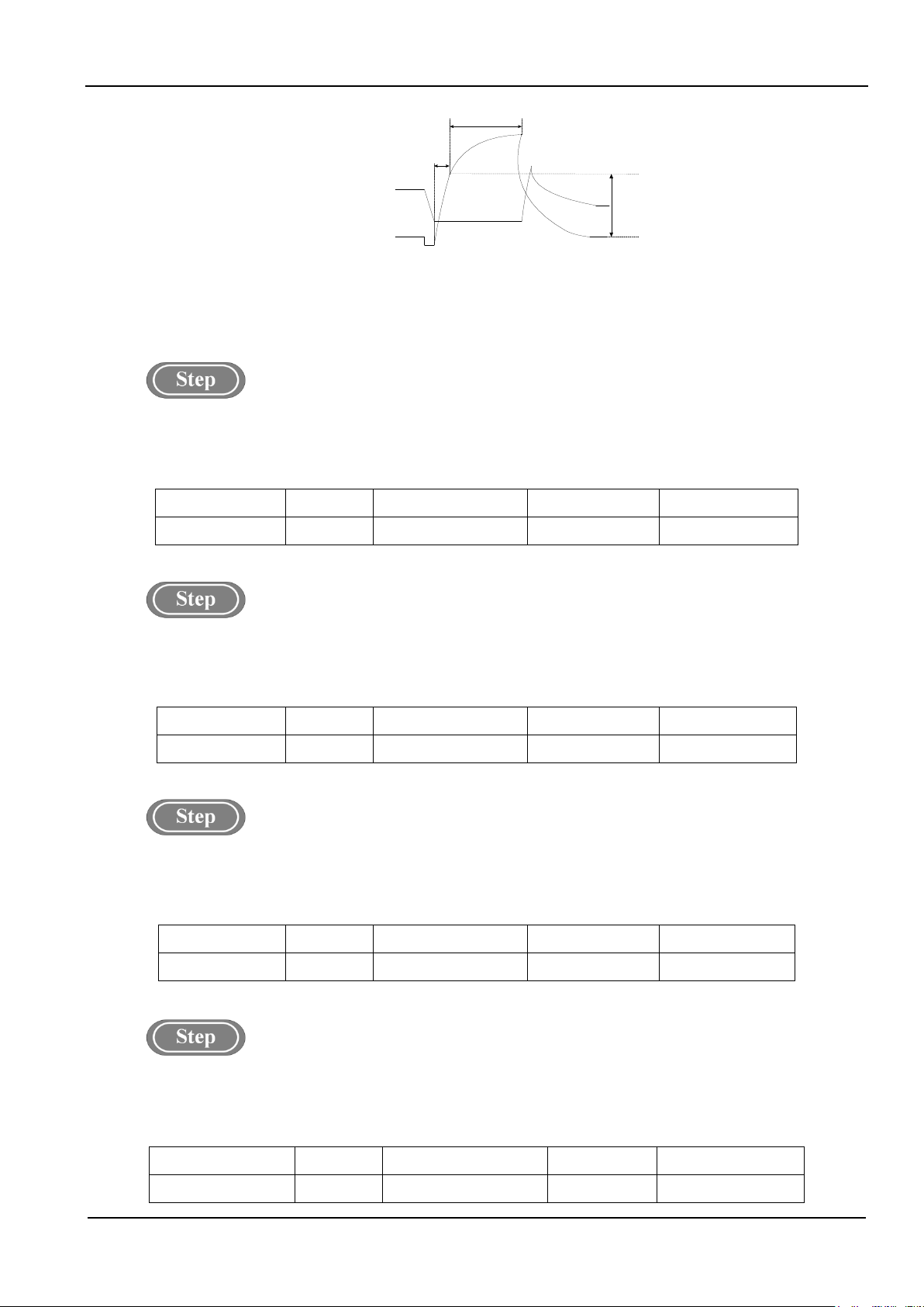
FastRising Slope of DC Welding Short-Circuit Current(F23)
Current rising speed changes during short-circuit time under DC welding status.
1. Enter into internal menu by long pressing “Function” key; turn the panel knob to F23.
2. Adjust F23parameters by rotating the right knob (table 3-12)
3. Press “Function” key again to exit from internal menu, F23parameter settings is completed.
Table3-12 Parameter Table ofQuick Rising Slope of DC Welding Short-Circuit Current
Function Code Unit Adjusting Range Step Length Default Value
F23 / 1~300 1 Automatic Matching
FastRising Amplitude of DC Welding Short-Circuit Current(F24)
Current rising speed amplitude during the short-circuit time under DC welding.
1. Enter into internal menu by long pressing “Function” key; turn the panel knob to F24.
2. Adjust F24parameters by rotating the right knob (table 3-13)
3. Press “Function” key again to exit from internal menu, F24 parameter settings is completed.
Table3-13Parameter Table ofQuickRising Amplitude of DC Welding Short-Circuit Current
Function Code Unit Adjusting Range Step Length Default Value
F24 A 0~500A 1A AutomaticMatching
12 Chapter III Dex CM3000
Full-Digital Control CO2/MAG/MIG Multi-FunctionWelding Machine
Voltage
Current
Slope
Amplitude
Arc Characteristic Slope
Fig.3-5Quick Rising Slope and Amplitude of Current
Welding Control(F25)
0 means two steps, 1 means four steps, 2 means special 4 steps, 3 means spot welding. Default value is
0(two steps)
1. Long press "Fn" key more than 3 seconds to enter into internal menu, turn the left knob to F25.
2. Turn the right knob to adjust parameters under F25 (shown in table 3-14).
3. Short press "Fn" key to exit internal menu, F25parameter settings is completed.
Table3-14 Welding Control Parameter
Function Code Unit Adjusting Range Step Length Default Value
F25 s 0~3 1 0 (2 Steps)
Percentage of wire feeding speed in arc starting stage (F26)
1. Long press "Fn" key more than 3 seconds to enter into internal menu, turn the left knob to F26.
2. Turn the right knob to adjust parameters under F26 (shown in table 3-15).
3. Short press "Fn" key to exit internal menu, F26 parameter settings is completed.
Table 3-15 Parameters for Percentage of wire feeding speed in arc starting stage
Function Code Unit Adjusting Range Step Length Default Value
F26 / 1~200 1 100
Synergic voltage corrected value in arc starting stage(F27)
1. Long press "Fn" key more than 3 seconds to enter into internal menu, turn the left knob to F27.
2. Turn the right knob to adjust parameters under F27 (shown in table 3-16).
3. Short press "Fn" key to exit internal menu, F27 parameter settings is completed.
Table3-16 Parameters of Synergic voltage corrected value in arc starting stage
Function Code Unit Adjusting Range Step Length Default Value
F27
-30~+30 1 0
Arc Dynamics in Arc Starting Stage(F28)
1. Long press "Function" key more than 3 seconds to enter into internal menu, turn the left knob to F28.
2. Turn the right knob to adjust parameters under F28 (shown in table 3-17).
3. Short press "Function" key to exit internal menu, F28 parameter settings is completed.
Table 3-17 Parameters of Arc Dynamics in Arc Starting Stage
Function Code Unit Adjusting Range Step Length Default Value
F28
-9~+9 1 0
This manual suits for next models
1
Table of contents
Popular Media Converter manuals by other brands

Apogee
Apogee DA-2000 Specifications

Globalmediapro
Globalmediapro HA-U1 Operation manual

Pepperl+Fuchs
Pepperl+Fuchs PCV-USB-RS485 quick start guide

Asus
Asus XONAR ESSENCE - Sound Card - 192 kHz quick start guide

SKYDANCE
SKYDANCE SA manual

Hall Research Technologies
Hall Research Technologies VHD-PCTV user manual


