Motrona IT210 User manual

Smart in Control –Sales@smartincontrol.com
IT210
Level Converter, Direction Signal Decoder and programmable pulse divider
Operating Manual
Product features:
•
Level Converter (RS-422, HTL Single Ended, HTL Differential,
TTL and andvice-versa
•
Implementation between the two types of representations for the direction
of rotation (A/B 90 °, A/B Direction and vice versa)
•
Adjustable division ratio of directional A / B pulses
•
Adjustable division ratio for the Z pulse
•
Reset of the Z divider by external input (defined setting)
•
Zero setting of the A / B / Z divider by external input (defined Start / Stop)
•
Z divider can also be used as an independent second divider
•
Limit frequency up to 1 MHz, depending on the input format
•
Push-pull outputs direct SPS control
•
9 to 30 VDC power supply

Smart in Control –Sales@smartincontrol.com
Page 2 / 23
Die deutsche Beschreibung ist verfügbar unter:
https://www.motrona.com/fileadmin/files/bedienungsanleitungen/It210_d.pdf
The English description is available at:
https://www.motrona.com/fileadmin/files/bedienungsanleitungen/It210_e.pdf
La description en français est disponible sur:
https://www.motrona.com/fileadmin/files/bedienungsanleitungen/It210_f.pdf
Version:
Description:
It210_01a/CF/ Oct 2018
Version 1
It210_01b/CF/ Feb 2019
First revision
It210_02a/AF/MBO/Dez 2019
IT210 extension
Legal notices:
All contents included in this manual are protected by the terms of use and copyrights of motrona GmbH. Any reproduction,
modification, usage or publication in other electronic and printed media aswell as in the internet requirespriorwritten
authorization by motronaGmbH.

Smart in Control –Sales@smartincontrol.com
Page 3 / 23
Table of Contents
Safety Instructions and Responsibility ................................................ 4
General Safety Instructions ....................................................................... 4
Use according to the intended purpose ......................................................... 4
Installation........................................................................................... 5
Cleaning, Maintenance and Service Notes ................................................ 5
Compatibility Hint ....................................................................... 6
Introduction .............................................................................. 7
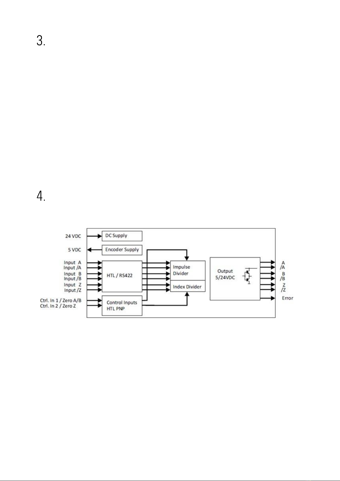
Block diagram ........................................................................7
Electrical Connections .................................................................. 8
DC Power Supply .............................................................................. 8
Auxiliary Voltage Output .......................................................................... 8
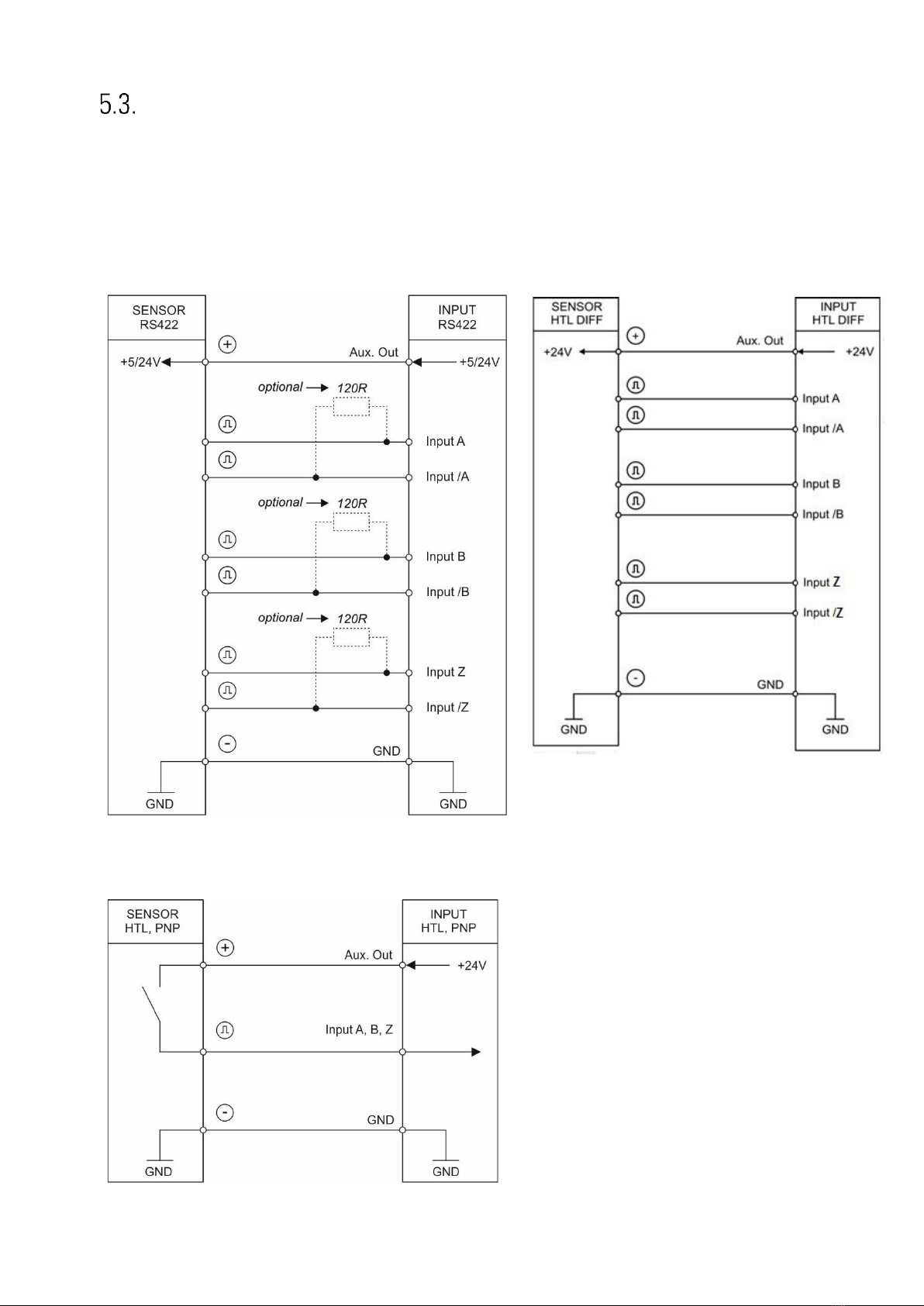
Incremental Inputs A, /A, B, /B, Z, /Z .......................................................... 9
Control Inputs ......................................................................................10
Pulse output ........................................................................................10
Error Ausgang.................................................................................11
LED .............................................................................................11
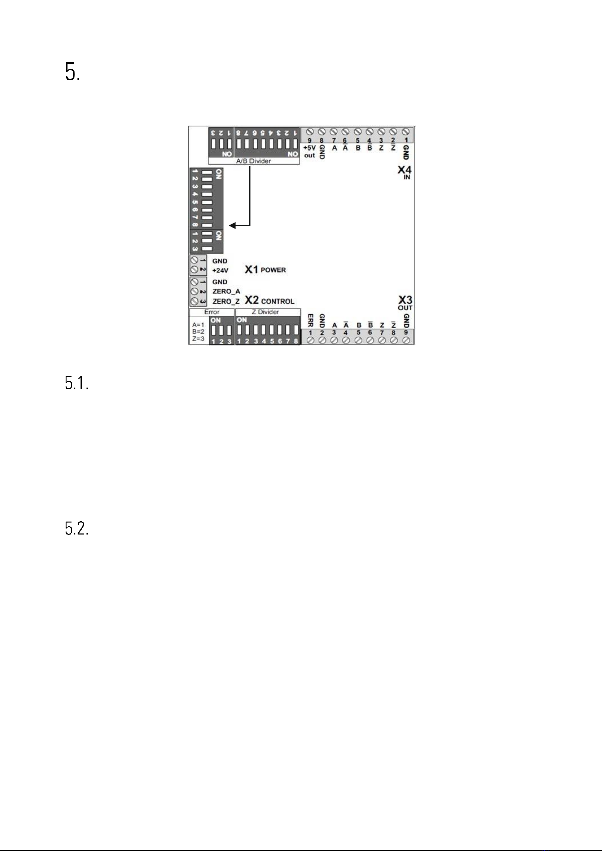
Input and output configuration ....................................................... 12
Level converter A/B Pulse (A/B Divider: All OFF).............................................13
Input/Output Mode Converter (A/B Divider: All OFF)........................................13
Adjustable divider A/B................................................................. 14
Setting the A/B Divider (at A/B Dir to A/B 90°) ...............................................14
Setting the A/B divider (for all other modes) .................................................15
Setting to zero the A/B divider with ZERO_A Signal..........................................17
Informationen over the signal change A/B Dir ................................................17
Adjustable divider Z .................................................................... 18
Pegel conversion Z Puls (Z Divider: all OFF) ...................................................18
Setting the Z Divider ..............................................................................18
Location and width of the Z pulse...............................................................19
Independent Z Divider ............................................................................20
Automatic generation of a Z pulse ..............................................................21
Reset the Z divider with ZERO_Z Signal ........................................................21
Dimensions.......................................................................... 22
Technical Specifications ............................................................... 23

Smart in Control –Sales@smartincontrol.com
Page 4 / 23
Safety Instructions and Responsibility
General Safety Instructions
This operation manual isa significant component of the unit and includes important rules and
hintsabouttheinstallation, functionandusage.Non-observancecanresultindamageand/or
impairment of the functions to the unit or the machine or even in injury to persons using the
equipment!
Pleasereadthe followinginstructionscarefullybeforeoperatingthedeviceandobserveall
safety and warning instructions! Keep the manual for later use.
Apertinent qualificationofthe respectivestaffisafundamental requirementinordertouse
these manual. The unit must be installed, connected and put into operation by a qualified
electrician.
Liability exclusion: The manufacturer is not liable for personal injury and/or damage to property
andforconsequentialdamage, duetoincorrecthandling, installation andoperation. Further
claims, due to errors in the operation manual as well as misinterpretations are excluded from
liability.
In addition the manufacturer reserve the right to modify the hardware, software or operation
manual at any time and without prior notice. Therefore, there might be minor differences
between the unit and the descriptions in operation manual.
The raiser respectively positioner isexclusively responsible for the safety ofthe system and
equipment where the unit will be integrated.
During installation or maintenance all general and also all country- and application-specific
safety rules and standards must be observed.
If the device is used in processes, where a failure or faulty operation could damage the system
orinjure persons, appropriate precautions toavoidsuchconsequences mustbetaken.
Use according to the intended purpose
The unit isintended exclusively for use inindustrial machines, constructions and systems. Non-
conforming usage does not correspond to the provisions and lies within the sole responsibility
of the user. The manufacturer is not liable for damages which has arisen through unsuitable
and improper use.
Please note that device may only be installed in proper form and used in a technically perfect
condition - in accordance to the “Technical Specifications” (see chapter 10). The device isnot
suitable for operation in explosion-proof areas or areas which are excluded by the EN 61010-1
standard.

Smart in Control –Sales@smartincontrol.com
Page 5 / 23
Installation
The device is only allowed to be installed and operated within the permissible temperature
range.Pleaseensureanadequateventilationandavoidalldirectcontactbetweenthedevice
and hot or aggressive gases and liquids.
Before installation or maintenance, the unit must be disconnected from all voltage-sources.
Further it must be ensured that no danger can arise by touching the disconnected voltage-
sources.
Devices which are supplied by AC-voltages, must be connected exclusively by switches,
respectively circuit-breakers with the low voltage network. The switch or circuit-breaker must
be placed as near as possible to the device and further indicated as separator.
Incoming as well as outgoing wires and wires for extra low voltages (ELV) must be separated
from dangerous electrical cables (SELV circuits) by using a double resp. increased isolation.
All selected wires and isolations must be conform to the provided voltage- and temperature-
ranges. Further all country- and application-specific standards, which are relevant for structure,
form and quality of the wires, must be ensured. Indications about the permissible wire cross-
sections for wiring are described in the Technical Specifications (see chapter 10).
Before first start-up it must be ensured that all connections and wires are firmly seated and
securedinthe screwterminals.All(inclusivelyunused)terminalsmustbefastenedbyturning
the relevant screws clockwise up to the stop.
Overvoltagesattheconnectionsmustbelimitedtovaluesinaccordancetotheovervoltage
category II.
Forplacement,wiring,environmentalconditionsaswellasshieldingandearthing/groundingof
thesupply lines thegeneralstandards of industrialautomation industryand thespecific
shieldinginstructions of the manufacturerare valid.Please find all respectivehintsandruleson
https://www.motrona.com/en/support
-->“[General EMC Rules for Wiring, Screening and
Earthing]”.
Cleaning, Maintenance and Service Notes
To clean the front of the unit please use only a slightly damp (not wet!), soft cloth. For the rear
nocleaning isnecessary. For an unscheduled, individual cleaning of the rear the maintenance
staff or assembler is self-responsible.
Duringnormaloperationnomaintenanceisnecessary.Incaseofunexpectedproblems,failures
ormalfunctions thedevice must be shipped for back tothe manufacturer forchecking,
adjustment and reparation (if necessary). Unauthorized opening and repairing can have
negative effects or failures to the protection-measures of the unit.

Smart in Control –Sales@smartincontrol.com
Page 6 / 23
Compatibility Hint
Themaindifferences between the IT210and therespective predecessor model IT251arelisted
below:
IT251
IT210
Housing
251
210
Input
RS422/DSUB
HTL/clamps
clamps
Input characteristics
RS422/HTL Single
RS422/HTL Diff/HTL
Single/TTL
Frequency
Max. 300kHz
1MHz/1MHz/350kHz/350kHz
Output
RS422/DSUB
HTL/clamps
Parallel outputs
clamps
Only 1 output
Encoder supply
5.5V/130mA
5.5V/250mA
Temperature
0..45°
0..60°
MTBF
55,4a
109,3a
Supply
18..30V
9..30V (supply determines the
nominal output level)
Input type
A/B90°
A/BDir
APuls/BPuls
A/B90°
A/BDir
-
A/B-divider
1:4096
1:4096
Z-divider
1:256
1:256
Zero pulse length
Adjustable
Adjustable

Smart in Control –Sales@smartincontrol.com
Page 7 / 23
Introduction
The IT210 isa universal interface using with incremental measuring systems.
The device allows the solution of the following problems:
•
Level conversion (RS-422, HTL single ended, HTL differential, TTL and vice versa)
•
Division of two-track A / B pulses with adjustable ratio 1: 1 to 1: 4096
•
Division of the Z pulse with adjustable ratio 1: 1 to 1: 256
•
External HTL signals for various functions
•
Implementation between the two types of representations for the direction of rotation
(A/B 90 °, A/B Dir and vice versa, Division possible)
•
Start /stop functionality via external ZERO_A signal
All settings are made on the DILL switches on the housing. The device consists of a compact
housing with screw terminals and can be mounted on a DIN rail.Block diagram
Block diagram

Smart in Control –Sales@smartincontrol.com
Page 8 / 23
Electrical Connections
The terminal screws should be tightened with a slotted screwdriver (blade width 2mm).
DC Power Supply
The device is supplied with a DC voltage between 9 ... 30 VDC via terminals 1 and 2 of X1. The
current consumption depends on the level ofthe supply voltage and the settings and is approx.
35 mA without load from the sensor supply and additional on the extracted encoder current at
the auxiliary voltageoutput.
All GND terminals are internally interconnected.
Auxiliary Voltage Output
At terminal 8 and 9 of X4 the auxiliary voltage as encoder / sensor supply is +5.5 VDC and can
be charged with max. 250 mA.

Smart in Control –Sales@smartincontrol.com
Page 9 / 23
Incremental Inputs A, /A, B, /B, Z, /Z
At terminal 2 ... 7 of X4, 3 pulse inputs are available for HTL / TTL / RS422 signals. The unused
inputsmust beopen (HTL single ended vs. HTL differential) or terminated (unused Ztrack in RS-
422 or HTL differentialformat).
Wiring of the incremental inputs:
RS422
HTL DIFFERENTIAL
HTL PNP

Smart in Control –Sales@smartincontrol.com
Page 10 / 23
Please note that all input and output signals refer to the same common
potential (GND) which at the same time is also the minus potential of the
power supply.
Atanytime, the totaltransmissioncharacteristicsofencoder, external
components and capacity of the cable must ensure proper signals at the
input terminals ofthe unit, with respect tothe levels, the shape and the
phase displacement A/B.
Control Inputs
Two control inputs with HTL PNP characteristics are available at terminals 2 and 3 of X2 and
are used for resetting the internal dividers
Unconnected control inputs are always “LOW”.
All inputs are designed to receive impulses from an electronic impulse source.
Notice for mechanical switching contacts:
When exceptionally mechanical contacts are used,pleaseconnectan external capacitor
between GND (-) and the corresponding input (+). A capacity of10 µF will reduce the input
frequency to
20 Hz and miscounting due to contact bouncing will be eliminated.
Pulse output
Depending on the DIL switch setting, the pulses are available in HTL or RS-422 format at the
outputs of screw terminal X3 and are independent of the used format. The height of the pulse
levelatthepush-pulloutputsintheHTLsettingcorrespondsapproximately totheinputvoltage
at the supply input X1.

Smart in Control –Sales@smartincontrol.com
Page 11 / 23
Error Ausgang
An HTL error signal (input error, only with RS-422 or HTL differential) isavailable at the X3
screw terminal 1. (Error = low).
The error is triggered by a line fault (short circuit or line break) by the input lines A, / A, B, / B or
Z, / Z. (Test mode OFF, DIL2 / 2 = OFF.
The DIL switch DIL3 (right, 3-pin) can be used to select the corresponding channel. If the DIL3 /
1 contact is set to OFF, no errors are evaluated on the A, / A line, DIL3 / 2 refers to the line B, /
B and DIL3 / 3 to the line Z, / Z.
An error can only be detected in RS-422 or HTL differential format, all other formats will not
trigger an error.
LED
Thegreen LEDindicatesoperational readiness(powersupplyswitchedon).
The yellow LED signals aninput error. (only with RS-422 or HTL differential)

Smart in Control –Sales@smartincontrol.com
Page 12 / 23
Changes in the settings on the DIL switches will only be taken over by the
device after the supply voltage has been switched on again!
Input and output configuration
Configuration
DIL1 (Front 8-pole)
Function
1
2
3
4
5
6
7
8
ON
Level for HTL Single Ended: UL< 10V / UH> 14V
OFF
Level for HTLSingle Ended: U < 5V/ U > 9V
ON
ON
Input format: TTL
ON
OFF
Input format: HTL Single Ended
OFF
ON
Input format: RS-422
OFF
OFF
Input format: HTL Differential
ON
ON
Z-pulse length:1 Z-Puls,independentofA/B
OFF
ON
Z-pulse length: ynchronized with AOUT / BOUT
ON
OFF
Z-pulse length: synchronized with AIN / BIN
OFF
OFF
Z-pulse length: 1 Z-Puls, a depending onA/B
ON
Input Mode : A/B Dir (Pulse / Direction)
OFF
Input Mode : A/B 90°
ON
Output Mode : A/B Dir (Pulse / Direction)
OFF
Output Mode : A/B 90°
ON
ZERO_A : Zero setting delayed, no errors
OFF
ZERO_A : Zero setting immediately, error
possible
ON
Highest divider for A / B divider on (2048)
OFF
Highest divider for A / B divider off (2048)
Configuration
DIL2 (Front 3-pole)
Function
1
2
3
ON
Z-pulse: Generation of a Z-pulse from AIN & BIN, AOUT & BOUT
OFF
Z-pulse: Z input is used
OFF
Test mode deactivated:OFF
ON
Output format : HTL Differential, HTL Single Ended (UX1(2) –2V)
OFF
Output format: RS-422, TTL (5V)

Smart in Control –Sales@smartincontrol.com
Page 13 / 23
Level converter A/B Pulse (A/B Divider: All OFF)
If the A/B pulse have to be switched unchanged from the input to the output (no division, no
change in length and position), then the DIL switch position listed below must be chosen. A
level conversion is only possible if the input mode (A/B 90 ° or A/B dir) corresponds to the
output mode. (DIL1/6 = DIL1/7).
Divider [A/B]
DIL5
(Left 8-pole)
DIL6
(Left 3-pole)
DIL1
(Front)
Comment
1
2
3
4
5
6
7
8
1
2
3
8
Binary value
1
2
4
8
16
32
64
128
256
512
1024
2048
OFF
OFF
OFF
OFF
OFF
OFF
OFF
OFF
OFF
OFF
OFF
OFF
AIN=AOUT,BIN= BOUT
Input/Output Mode Converter (A/B Divider: All OFF)
If input mode differs from output mode and in addition, the DIL switches DIL5 and DIL6 of the
divider A/B are all set to OFF, the following signal characteristics are set up at the output.
Case 1: Input A/B 90°, Output A/B Dir
DIL1/6 = OFF, DIL1/7 = ON with A/B Divider setting: DIL5, 6 = all OFF
If the direction of the A/B 90 ° signal changes at the input, a change takes place at the BOUT
output signal. (A/B dir). There is no division.
Case 2: Input A/B Dir, Output A/B 90°
DIL1/6 = ON, DIL1/7 = OFF with A/B Divider setting: DIL5, 6 = all OFF
If a change takes place at the BIN input signal (A/B dir), the direction of the A/B 90 ° signal
changes attheoutput.Hereisadivision 1:2,fromthe inputinrelationtotheoutput.

Smart in Control –Sales@smartincontrol.com
Page 14 / 23
Adjustable divider A/B
Setting the A/B Divider (at A/B Dir to A/B 90°)
ThedivisionratiofortheA/BpulsesissetattheDILswitchesDIL5andDIL6.Theswitch
positions use a binary code like shown in the subsequent list. (DIL1/6 = ON, DIL1/7 = OFF).
Divider [A/B]
DIL5
(Left 8-pole)
DIL6
(Left 3-pole)
DIL1
(Front)
Comment
1
2
3
4
5
6
7
8
1
2
3
8
Binary value
division=>
1 : (Binary value +1) x2
1
2
4
8
16
32
64
128
256
512
1024
2048
ON
OFF
OFF
OFF
OFF
OFF
OFF
OFF
OFF
OFF
OFF
OFF
value 1 => 1 : 4
OFF
ON
OFF
OFF
OFF
OFF
OFF
OFF
OFF
OFF
OFF
OFF
value 2 => 1 : 6
ON
ON
OFF
OFF
OFF
OFF
OFF
OFF
OFF
OFF
OFF
OFF
value 3 => 1 : 8
OFF
OFF
ON
OFF
OFF
OFF
OFF
OFF
OFF
OFF
OFF
OFF
value 4 => 1 : 10
ON
OFF
ON
OFF
OFF
OFF
OFF
OFF
OFF
OFF
OFF
OFF
value 5 => 1 : 12
OFF
...etc.
OFF
OFF
OFF
OFF
OFF
OFF
OFF
OFF
OFF
ON
OFF
OFF
1 : 1026
OFF
OFF
OFF
OFF
OFF
OFF
OFF
OFF
OFF
OFF
ON
OFF
1 : 2050
ON
ON
ON
ON
ON
ON
ON
ON
ON
ON
ON
OFF
1 : 4096
ON
ON
ON
ON
ON
ON
ON
ON
ON
ON
ON
ON
1 : 8192
Example: Input A/B dir, output A/B 90 ° with A/B division 1:6 (setting DIL6, 5: OFFONOFF)
Division 1:2: See Input/Output Mode Conversion (A/B Divider: All OFF)

Smart in Control –Sales@smartincontrol.com
Page 15 / 23
Setting the A/B divider (for all other modes)
The division ratio for the A/B pulses is set at the DIL switches DIL5 and DIL6. The switch
positions use a binary code like shown in the subsequent list. (DIL1/6 = OFF, DIL1/7 = X).
Divider [A/B]
DIL5
(Left 8-pole)
DIL6
(Left 3-pole)
DIL1
(Front)
Comment
1
2
3
4
5
6
7
8
1
2
3
8
Binary value
division=>
1 : Binary value +1
1
2
4
8
16
32
64
128
256
512
1024
2048
ON
OFF
OFF
OFF
OFF
OFF
OFF
OFF
OFF
OFF
OFF
OFF
value 1 => 1 : 2
OFF
ON
OFF
OFF
OFF
OFF
OFF
OFF
OFF
OFF
OFF
OFF
value 2 => 1 :3
ON
ON
OFF
OFF
OFF
OFF
OFF
OFF
OFF
OFF
OFF
OFF
value 3 => 1 :4
OFF
OFF
ON
OFF
OFF
OFF
OFF
OFF
OFF
OFF
OFF
OFF
value 4 => 1 :5
ON
OFF
ON
OFF
OFF
OFF
OFF
OFF
OFF
OFF
OFF
OFF
value 5 => 1 :6
OFF
ON
ON
OFF
OFF
OFF
OFF
OFF
OFF
OFF
OFF
OFF
value 6 => 1 :7
ON
ON
ON
OFF
OFF
OFF
OFF
OFF
OFF
OFF
OFF
OFF
value 7 => 1 :8
OFF
...etc.
OFF
OFF
OFF
OFF
OFF
OFF
OFF
OFF
OFF
ON
OFF
OFF
1 : 513
OFF
OFF
OFF
OFF
OFF
OFF
OFF
OFF
OFF
OFF
ON
OFF
1 : 1025
ON
ON
ON
ON
ON
ON
ON
ON
ON
ON
ON
OFF
1 : 2048
ON
ON
ON
ON
ON
ON
ON
ON
ON
ON
ON
ON
1 : 4096
Example: Input A/B 90°, output A/B 90 ° with A/B division 1:6 (setting DIL6, 5: OFF ON OFF

Smart in Control –Sales@smartincontrol.com
Page 16 / 23
Example: Input A/B 90°, output A/B 90 ° with A/B division 1:3 (setting DIL6, 5: OFF ON OFF
Example: Input A/B 90°, output A/B 90 ° with A/B division 1:3 (setting DIL6, 5: OFF ONOFF

Smart in Control –Sales@smartincontrol.com
Page 17 / 23
Setting to zero the A/B divider with ZERO_A Signal
The divider will only be reset in the zero phase of the output signals AOUT and BOUT and will
remain as long as the signal is attached. This prevents the miscounting of subsequent circuits.
This function can only be applied to A/B 90°, it is independent of the divider ratio.
Ifthereisahigh signalatZERO_AtheA/Bdividerisreset and hasthestarting state AOUT =
BOUT = Low. The divider is in a defined state. Depending on the direction of the input signals,
thenextsplitA/Bpulseappears immediatelyafter the reset,or after theset divisionratio.The
length oftheZERO_Apulse hastobegreaterthan theperiodoffrequency, than itcanbe
switched off. This feature can be used for define start and stop.
TheZtrackcanbesettozerowiththeZERO_Ainput.TheDILswitchDIL1/8hasbeensetto
ON, A/B 90 ° output signals have been selected and the Z Pulse length has been synchronized
to the output.
Informationen over the signal change A/B Dir
Signal changes from B (direction) should appear shortly before or latest at the same time as the
A flank so that the change can be detected correctly.

Smart in Control –Sales@smartincontrol.com
Page 18 / 23
Adjustable divider Z
Pegel conversion Z Puls (Z Divider: all OFF)
If the Z pulse have to be switched unchanged from the input to the output (no division, no
change in length and position), then the DIL switch position listed below must be chosen.
Divider [Z]
DIL4 (right 8-pole)
Comment
Binary value
1
2
3
4
5
6
7
8
1
2
4
8
16
32
64
128
OFF
OFF
OFF
OFF
OFF
OFF
OFF
OFF
ZIN = ZOUT (ZERO_Z = Low)
The output at the level conversion can be set to zero (ZOUT = Low) with the control input X2(3)
ZERO_Z = High.
The function is active as long as there is a high level at the control input. The Z pulse can be
trimmed by switching.
Setting the Z Divider
The programming of the Z divider is subject to the same rules as the programming of the A/B
divider.
Divider [Z]
DIL4 (right 8-pole)
Comment
Binary value
Divider => 1: Binary value +1
1
2
3
4
5
6
7
8
1
2
4
8
16
32
64
128
ON
OFF
OFF
OFF
OFF
OFF
OFF
OFF
1 : 2
OFF
ON
OFF
OFF
OFF
OFF
OFF
OFF
1 : 3
ON
ON
OFF
OFF
OFF
OFF
OFF
OFF
1 : 4
OFF
OFF
ON
ON
ON
ON
ON
ON
1 : 253
ON
OFF
ON
ON
ON
ON
ON
ON
1 : 254
OFF
ON
ON
ON
ON
ON
ON
ON
1 : 255
ON
ON
ON
ON
ON
ON
ON
ON
1 : 256

Smart in Control –Sales@smartincontrol.com
Page 19 / 23
Location and width of the Z pulse
If the DIL switch DIL4 of the Z divider is completely set to OFF, the Z Pulse is forwarded from
the input directly to the output (see level conversion Z Puls).
Allpictures inthissection assumethattheA/Bdividerissetto8.TheZPulse isdivided
accordingtoitsdivider (additionally DIL2/1 on OFF,ZINisused, Zdividers not complete on
OFF).
Depending on the length or location of the Z Pulses input and through the synchronization to
the input or output signals, the Z pulse at the output can fluctuate around an input or output
period (not with DIL1/5 = DIL1/4 = ON).
DIL1 Front
8-pole
Wide Z pulse (a full encoder turn)
4
5
ON
ON
The pulse width at the output corresponds to the full distance between two Z
pulses at theinput.
DIL1 Front
8-pole
Narrow Z pulse (1/4 output-periode)
(Only applicable to input signals A/B 90°, DIL1/6 = OFF)
4
5
OFF
ON
The pulse width at the output corresponds to ¼ period of pulse width at the input.

Smart in Control –Sales@smartincontrol.com
Page 20 / 23
DIL1Front
8-pole
Narrow Z pulse (1/4 output-periode)
(Only applicable to output signals A/B 90°, DIL1/7 = OFF)
4
5
ON
OFF
The pulse width at the output corresponds to ¼ period of pulse width at the
output.
In this operation mode, only division ratios may be used, which together with the A/B divisor
deliver clear and completely results. A division with rest causes that the Z pulse at the output
can fluctuate around an input or output period.
Example:
Ifatanencoderwith 1000 pulses theA/B deviderweresetto3and at the same time the Z
Pulse divider were set to 2, then the Z Pulse at the output would have to appear after 666,666
pulses, which is not physically possible.
Independent Z Divider
TheZ dividerworksindependently ofthe A/B track,thedirectional evaluationofthe A/B signal
does not affect the counting sequence (additionally DIL2/1 on OFF, ZIN is used, Z divider not
completely set to OFF).
DIL1 Front
8-pole
Wide Z pulse (a full encoder turn)
4
5
ON
ON
The pulse width at the output corresponds tothe full distance between two
Z pulses at the input.
Other manuals for IT210
1
Table of contents
Other Motrona Media Converter manuals

Motrona
Motrona PU 210 User manual

Motrona
Motrona IO221 User manual

Motrona
Motrona ES001 User manual

Motrona
Motrona IT210 User manual

Motrona
Motrona PU 204 User manual

Motrona
Motrona SI 251 User manual

Motrona
Motrona SV211 User manual

Motrona
Motrona UF251 User manual

Motrona
Motrona IO220 User manual

Motrona
Motrona GV204 User manual

Motrona
Motrona GV224 User manual

Motrona
Motrona FP210 User manual

Motrona
Motrona PU202 User manual

Motrona
Motrona UZ210 User manual

Motrona
Motrona GV210 User manual

Motrona
Motrona PU 204 User manual

Motrona
Motrona IV 251 User manual

Motrona
Motrona FM210 User manual

Motrona
Motrona IT251 User manual

Motrona
Motrona SV 210 User manual