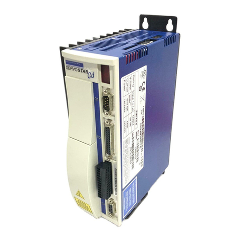
Megmeet SPS-NE Series User manual

1
SPS-NE Series Bus-type Servo Drive
Simplified User Manual
Document Version: V1.1
Archive Date: 2024/01/24
BOM Code
Shenzhen Megmeet Electrical Co., Ltd. provides professional technical support for
our customers. You can contact the local branch office or customer service center,
or directly contact the company headquarters.
Shenzhen Megmeet Electrical Co., Ltd.
All rights reserved. The contents in this document are subject to change without
notice.
Shenzhen Megmeet Electrical Co., Ltd.
Address: 5th Floor, Block B, Unisplendor Information Harbor, Langshan Road,
Nanshan District, Shenzhen, 518057, China
Zip code: 518057
Website: https://www.megmeet.com/
Tel: +86-755-86600500
Fax: +86-755-86600562

2
Foreword
Thank you for choosing the SPS-NE series servo drive manufactured by Megmeet.
SPS-NE servo drive, developed on a new hardware platform and featured with excellent performance, fully-fledged
functions, compact structure, simple installation, easy commissioning and maintenance, is an ideal product with
favorable price-performance ratio in the servo drive market for both general purposes and OEM.
SPS-NE servo drive adopts Ethernet communication interface, supports EtherCAT communication protocol, and
realizes networked operation of single servo drive or multiple servo drives in cooperation with the host controller. It
can be applied in machine tool feed shafts, printing, textile, cutting, manipulators, punch presses, semiconductor
welding machines and so on, achieving fast and accurate control on position, speed and torque.
This manual provides instructions and precautions for wiring, parameter setting, fault diagnosis and troubleshooting.
In order to ensure the correct installation and operation of the SPS-NE series servo drive, and to unlock its full
potential, please read this manual carefully before installation, keep the manual properly and give it to the actual
user when necessary.
Unboxing inspection
When you unbox the product, remember to check the following:
whether there is any damage on the drive;
whether the rated values on the nameplate are the same as what you ordered;
whether the included wires are intact and can be connected for use.
Our company has implemented strict inspection on the product’s manufacturing and packaging. If there is still any
error, please contact us or the local distributor.
We are engaged in the continuous improvement of drives. The relevant manuals provided by us are subject to
change without notice.

3
Safety precautions
Indicates that failure to comply with the notice can result in death or severe personal injuries.
Indicates that failure to comply with the notice may result in moderate or minor personal injuries
or equipment damage.
Install the product on incombustible materials such as metal. Failure to comply will result in a fire.
Do not install the product near combustible objects. Failure to comply will result in a fire.
Do not install the product in places with explosive gases. Otherwise, there will be an explosion.
The wiring work must be done by professional personnel. Otherwise, there will be an electric shock.
Before wiring, check that the main and control power supplies are cut off. Otherwise, there will be an electric
shock.
Properly connect the grounding terminal of the drive. Otherwise, there will be an electric shock.
Properly close the cover before power-on. Otherwise, electric shock or explosion may occur.
When powering on a drive that has been stored for 2 years, use a voltage regulator to increase voltage
gradually. Otherwise, electric shock or explosion may occur.
To avoid electric shock, do not touch terminals when the drive is powered on.
To avoid electric shock, do not operate the drive with wet hands.
Before conducting maintenance, ensure that the power is cut off for 10 minutes, and check that the charging
indicator is completely off or the voltage of bus negative/positive is below 36 V. Failure to comply will result in
an electric shock.
Only professional personnel is qualified to replace the components. Do not leave any wire or metal parts inside
the drive. Failure to comply will result in a fire.
The bare parts of the terminal lugs in the main circuit must be wrapped with insulation tape. Otherwise,
electric shock may occur.

4
Install the product on the place that can bear the weight. Failure to comply will result in personal injuries or
equipment damage.
Do not install the drive near water pipes or other places with water splash. Otherwise, there will be equipment
damage.
Take care not to drop screws, gaskets, metal bars and the like into the drive. Otherwise, fire and equipment
damage may occur.
If the drive is damaged or lack of components, do not run the drive. Failure to comply will result in a fire or
personal injuries.
Do not install the product in the place exposed to direct sunlight. Otherwise, there will be equipment damage.
Cable lugs must be firmly connected to main circuit terminals. Otherwise, there will be equipment damage.
Do not install the servo drive in places with vibration beyond the specification. Otherwise, there will be
equipment damage.

5
Contents
SPS-NE Series Bus-type Servo Drive.....................................................................................1
Chapter 1 Specifications........................................................................................................ 7
Servo drive .......................................................................................................................................................7
Product nameplate........................................................................................................................................7
Product series ................................................................................................................................................. 7
Technical specifications............................................................................................................................... 8
Product appearance....................................................................................................................................10
Product dimensions..................................................................................................................................... 10
Chapter 2 System wiring......................................................................................................12
Basic operation wiring ................................................................................................................................ 12
Main circuit terminals and functions .......................................................................................................13
Control circuit terminals and functions (CN2) ...................................................................................... 13
Control circuit signal wiring ....................................................................................................................... 15
Encoder interface wiring and signal definition (CN3) .........................................................................16
Serial communication interface definition (CN1)..................................................................................18
Ethernet communication interface definition (CN4, CN5).................................................................19
Chapter 3 Parameter setting..............................................................................................20
Operating parameters ................................................................................................................................20
Monitoring parameters .............................................................................................................................. 27
Communication parameters .....................................................................................................................28
Chapter 4 Function and Application.................................................................................. 31
Trial operation ...............................................................................................................................................31
Speed mode ..................................................................................................................................................36
Position control.............................................................................................................................................39

6
Spindle/Positioning homing.......................................................................................................................42
Control mode selection .............................................................................................................................. 46
Chapter 5 EtherCAT Communication................................................................................ 47
Overview of EtherCAT bus ........................................................................................................................47
Bus function of SPS-NE .............................................................................................................................. 48
CiA402 device control (device conventions) ........................................................................................ 55
Objects of drive parameters .....................................................................................................................82
Chapter 6 Troubleshooting................................................................................................. 83
Chapter 7 Parameter list......................................................................................................91
Appendix 1 Warranty and Service....................................................................................158
Parameter Recording Table...............................................................................................160

7
Chapter 1 Specifications
Servo drive
Fig. 1-1 Naming rule of SPS-NE servo drives
The model on the nameplate of the servo drive displays the product series, voltage class, power rating and other
information.
Product nameplate
Fig. 1-2 Product nameplate
Product series
SIZE
Product
model
Rated
capacity
(kVA)
Rated
input
current
(A)
Rated
output
current
(A)
Rated
output
power
(kW)
Compatible
motor
power
(kW)
Minimum
braking
resistor
(Ω)
Braking
torque
(%)
Fuse
(A)
B
SPS-4T1.5-NE
3.0
5.1
3.7
1.5
1.5
80
200
10

8
SIZE
Product
model
Rated
capacity
(kVA)
Rated
input
current
(A)
Rated
output
current
(A)
Rated
output
power
(kW)
Compatible
motor
power
(kW)
Minimum
braking
resistor
(Ω)
Braking
torque
(%)
Fuse
(A)
SPS-4T2.2-NE
4.0
5.8
5.5
2.2
2.2
80
200
10
SPS-4T3.0-NE
5.0
9.5
7.6
3.0
3.0
60
200
15
C
SPS-4T4.0-NE
6.0
11
9.0
4.0
4.0
50
200
15
SPS-4T5.5-NE
8.5
14.5
13.0
5.5
5.5
50
200
20
SPS-4T7.5-NE
11.0
20.5
17.0
7.5
7.5
40
200
32
D
SPS-4T11-NE
17.0
26.0
25.0
11
11
30
200
50
SPS-4T15-NE
21.0
35.0
32.0
15
15
25
200
60
(1) All servo drives of SPS-NE series have a braking unit built in. Users can add additional braking resistors in case of
dynamic braking. The above specifications of braking resistors are suitable for most applications. In case of special
applications and working conditions, consult our company.
(2) Drives with power higher than SPS-4T18.5-NE are still in development.
Technical specifications
Bus
specifications
Bus standard
CoE: IEC 61158 Type12, IEC 61800-7 CiA402 Drive Profile
Bus mode
Profile Position Mode
Profile Velocity Mode
Homing Mode
Interpolated Position Mode
Cyclic Synchronous Position Mode
Cyclic Synchronous Velocity Mode
Position
control
Reference source
Through EtherCAT bus
Reference control signal
Through EtherCAT bus

9
Electronic gear ratio
0.001≤a/b≤4000
Positioning completed sign
0–10000 Pulse
Torque limit
Parameter setting
Feedforward compensation
Parameter setting
Speed control
Reference control mode
Through EtherCAT bus
Torque limit
Internal parameter
Zero clamp
Internal parameter setting/EtherCAT bus setting
Speed reached threshold
Internal parameter setting/EtherCAT bus setting
Torque
control
Reference control mode
Internal setting
Speed limit
Internal setting
Digital input
and output
Digital input
Servo ON, external reset, gain switchover, mode switchover,
multi-position, zero clamp, torque limit, jogging, electronic gear
switchover, and so on
Digital output
Servo ready, servo fault, torque limited, zero clamp completed,
positioning completed, positioning near, speed limited, homing
completed, and so on
Environment
Operating site
No corrosive and combustible gases, no splash of water, oil and
drug
Altitude
≤1000 m: derating not required; > 1000 m: derated by 1% for
every additional 100 m
Ambient temperature
-10℃ to +50℃ (derating required if the ambient temperature is
40℃ to 55℃)
Humidity
5% to 95% RH, non-condensing
Vibration/Shock resistance
5.9 / 19.6 (unit: m/s2)

10
Product appearance
Fig. 1-3 Product appearance
Product dimensions
SIZE B:

11
SIZE C:
SIZE D:

12
Chapter 2 System wiring
Basic operation wiring
Fig. 2-1 Wiring diagram for basic operation
Frequency-division
output
Oriented stop completed
(/ORL-RDY)
Positioning completed
(/COIN)
Fault output
(/ALM)
Servo ready
(/S-RDY)
Servo ON
(/S-ON)
Speed/Position switchover
(/SPD/POS)
Oriented stop ON
(/ORL-ON)
Tapping ON
(/TAP-ON)
Emergency stop
(/ESD)
Spindle swing
(/SPDL-SW)
Reaming ON
(/RM-ON)
Fault reset
(/ALM-RST)
RS485 communication
CAN communication

13
Note: The figure takes the incremental encoder as the example. Sin/Cos encoders are also supported.
Connect the braking resistor between PB and P.
Main circuit terminals and functions
Terminal name
Function description
L1, L2, L3
Three-phase 380 V AC input terminals
L1C, L2C
Single-phase 220 V AC input terminals
(load current ≥2 A)
P, PB
Connect the external braking resistor
PE
Power grounding and motor grounding terminals (2)
U, V, W
Three-phase AC output terminals (connected to motor)
Control circuit terminals and functions (CN2)
Fig. 2-2 Arrangement of control signal pins

14
Type
Mark
Name
Function description
Note
Multi-func
tion input
terminals
DI1
Digital input
terminal 1
FWD
ON: Forward running
OFF: Stop
Optocoupler isolation input
Input impedance: 3.9 K
Maximum input frequency: 200 Hz
Input voltage range: 20 to 30 V
DI2
Digital input
terminal 2
Speed/Position switchover
terminal
OFF: Speed mode
ON: Position mode
DI3
Digital input
terminal 3
Spindle/Positioning homing
terminal
ON: Spindle homing
DI4
Digital input
terminal 4
Tapping enable
ON: Switched to the tapping
mode
DI5
Digital input
terminal 5
Emergency stop
ON: Emergency stop
DI6
Digital input
terminal 6
Spindle swing
ON: Spindle swing
DI7
Digital input
terminal 7
Reaming enable
ON: Reaming enabled
DI8
Digital input
terminal 8
Fault rest
ON: Fault reset

15
Type
Mark
Name
Function description
Note
Multi-func
tion
output
terminals
DO1+
DO1-
Digital output
terminal 1
30: Spindle/Positioning homing
completed
Optocoupler isolation output
Maximum operating voltage: 30 V
Maximum output current: 100 mA
DO2+
DO2-
Digital output
terminal 2
25: Positioning completed
DO3+
DO3-
Digital output
terminal 3
16: Servo drive fault
RLA
RLB
Relay output
terminal
15: Servo drive ready
Power
24V
+24V power
supply
Provides external +24 V power
supply
Maximum output current: 100 mA
COM
+24V common
2 common terminals, used in
cooperation with other terminals
COM is isolated from the inner GND
Control circuit signal wiring
For DI/DO wiring, refer to the basic operation wiring diagram.
● Pulse frequency-division output
Host device differential reception
Host device optocoupler reception

16
Encoder interface wiring and signal definition (CN3)
SPS-NE servo drive supports four types of encoders including incremental encoders, sin/cos encoders,
absolute encoders and resolvers. The interfaces are defined as follows:
Incremental Encoder
Pin
Signal name
Description
Pin
Signal name
Description
1
A+
Encoder A+ signal
11
U+
Encoder U+ signal
2
A-
Encoder A- signal
12
U-
Encoder U- signal
3
B+
Encoder B+ signal
13
V+
Encoder V+ signal
4
B-
Encoder B- signal
14
V-
Encoder V- signal
5
Z+
Encoder Z+ signal
15
W+
Encoder W+ signal

17
6
Z-
Encoder Z- signal
16
W-
Encoder W- signal
7
+5V
5 V power output
Other
NC
Not connected
8
GND
Ground
20
L-
Motor temperature detection -
10
L+
Motor temperature
detection +
Housing
Shield
Shield
Sin/Cos Encoder
Pin
Signal name
Description
Pin
Signal name
Description
1
A+
Encoder A+ signal
11
C+
Encoder C+ signal
2
A-
Encoder A- signal
12
C-
Encoder C- signal
3
B+
Encoder B+ signal
13
D+
Encoder D+ signal
4
B-
Encoder B- signal
14
D-
Encoder D- signal
5
Z+
Encoder Z+ signal
Other
NC
Not connected
6
Z-
Encoder Z- signal
20
L-
Motor temperature
detection -
7
+5V
5 V power output
Housing
Shield
Shield
8
GND
Ground
10
L+
Motor temperature
detection +
Resolver (in development)
1
COS+
Encoder COS+ signal
2
COS-
Encoder COS- signal
3
SIN+
Encoder SIN+ signal
4
SIN-
Encoder SIN- signal

18
5
EXC+
Encoder EXC+ signal
6
EXC-
Encoder EXC- signal
10
L+
Motor temperature detection +
20
L-
Motor temperature detection -
Housing
Shield
Shield
Absolute Encoder (in development)
Pin
Signal name
Description
Pin
Signal name
Description
1
COS+
COS+ signal
11
DAT+
Differential communication
data signal +
2
COS-
COS- signal
12
DAT-
Differential communication
data signal -
3
SIN+
SIN+ signal
13
CLK+
Differential communication
clock signal + (only
applicable for Endat
protocol)
4
SIN-
SIN- signal
14
CLK-
Differential communication
clock signal - (only
applicable for Endat
protocol)
7
+5V
5 V power output
Other
NC
Not connected
8
GND
Ground
20
L-
Motor temperature
detection -
10
L+
Motor temperature
detection +
Housing
Shield
Shield
Serial communication interface definition (CN1)
Reserved.

19
Ethernet communication interface definition (CN4, CN5)
CN4 and CN5 are EtherCAT Ethernet communication connectors.
CN4 is the input interface connected to the communication line from the master station.
CN5 is the output interface connected to the next slave device.
The connector’s pin definitions are as follows:
Pin
Name
Description
Arrangement
1
TX+
Data transmission +
2
TX-
Data transmission -
3
RX+
Data reception +
4
-
5
-
6
RX-
Data reception -
7
-
8
Housing
PE
Shield
(1) The connector meets the 100M Ethernet standards.
(2) Selection of cables: both straight-through and cross-over cables are supported. It is recommended to choose
double-shielded CAT5E 100M Ethernet cables or better cables.

20
Chapter 3 Parameter setting
Operating parameters
1. Basic parameters
Function
code
Name
Value range
Default value
Change
P30.00
Servo control
switchover selection
0: Non-servo control
1: Speed/Torque←→Servo control
2: Servo←→Speed/Torque control
3: Servo control
4: Bus control
0
×
P02.00
Motor and mode
selection
Ones: Motor control mode selection
1: Vector control with PG
Tens: Motor type selection
0: Asynchronous motor
1: Synchronous motor
01
×
P02.01
Keypad enable
1: Enable keypad
0
○
P02.02
Operation command
channel selection
0: Keypad control
1: Terminal control
1
○
P02.03
Running direction
0: Forward
1: Reverse
0
○
P02.04
Source of main
frequency reference
0: Digital setting 1: Keypad ∧∨
1: Digital setting 2: Terminal UP/DN
2 to 5: Reserved
6: Process closed-loop PID
7 to 10: Reserved
0
○
This manual suits for next models
6
Table of contents
Other Megmeet Servo Drive manuals
Popular Servo Drive manuals by other brands
Parker
Parker Compax3 Fluid T40 Start-up
SMC Networks
SMC Networks LECSB Series Operation manual
Panasonic
Panasonic MINAS A6N Series operating instructions
UUMOTOR
UUMOTOR SVD48V Series manual

Pacific Scientific
Pacific Scientific 5630 Installation & hardware reference manual
ABB
ABB MicroFlex e190 Quick installation guide

