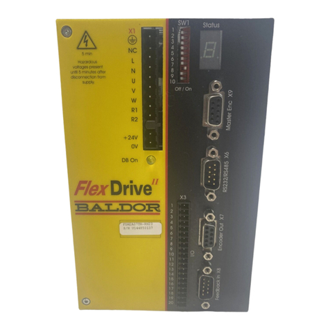
Baldor Flex+DriveII User manual

Flex+DriveII
Demonstration Unit
SERVO DRIVE
Operating Manual
03/02 MN1917


Contents iMN1917
Contents
1 General Information 1-1..............................................
2 Introduction 2-1......................................................
2.1 Features 2-1...........................................................................
2.1.1 Upgrade kits 2-1..........................................................................
3 Setup 3-1...........................................................
3.1 Introduction 3-1........................................................................
3.1.1 Controls and indicators 3-1.................................................................
3.1.2 Setup 3-2................................................................................
3.1.3 Drive enable switch 3-2....................................................................
3.1.4 Installing the software 3-2...................................................................
3.1.5 Starting WorkBench v5 3-3..................................................................
3.2 Commissioning and Tuning 3-4...........................................................
3.2.1 Using the Commissioning Wizard 3-4........................................................
3.2.2 Autotune mode 3-5........................................................................
3.2.3 Saving tuning information 3-5...............................................................
3.2.4 Fine-tuning mode 3-5......................................................................
4 Basic Demonstrations 4-1.............................................
4.1 Introduction 4-1........................................................................
4.1.1 Basic controls - input switches 4-1...........................................................
4.1.2 Basic controls - output LEDs 4-1.............................................................
4.1.3 Analog input 4-2..........................................................................
4.2 Demonstration files 4-3..................................................................
4.2.1 Preparation 4-3...........................................................................
4.2.2 Opening Mint (.mnt) program files 4-3........................................................
4.3 Preset moves 4-4.......................................................................
4.3.1 Testing Preset moves 4-5...................................................................
4.4 PLC Task 4-6..........................................................................
4.4.1 Testing the PLC Task 4-7...................................................................
4.4.2 Using Presets and the PLC Task simultaneously 4-7............................................
5 Applications 5-1.....................................................
5.1 Introduction 5-1........................................................................
5.2 Tool changer 5-2.......................................................................
5.2.1 Using the program 5-2.....................................................................
5.3 PLC program 5-3.......................................................................
5.3.1 Using the program 5-3.....................................................................
5.4 Following 5-4..........................................................................
5.4.1 Changing the master encoder source 5-4.....................................................
5.4.2 Performing an offset move 5-4..............................................................
5.4.3 Changing the follow ratio 5-5................................................................
5.5 MintMT ActiveX control 5-6..............................................................
5.5.1 Preparing the Flex+DriveII 5-6...............................................................
5.5.2 Starting the project 5-6.....................................................................
5.5.3 Inserting the ActiveX control 5-7.............................................................
ii Contents MN1917
5.5.4 Inserting command buttons 5-8..............................................................
5.5.5 Adding program lines (code) 5-9.............................................................
5.5.6 Opening the example VBA file 5-10...........................................................
5.5.7 Testing the form 5-10.......................................................................
6 Specifications 6-1....................................................
6.1 Introduction 6-1........................................................................

6.1.1 Specifications 6-1.........................................................................
Appendices
A Upgrade Kit A-1.....................................................
A.1 Introduction A-1........................................................................
A.2 Dismantling the demonstration unit A-1....................................................
A.2.1 Removing the Flex+Drive A-1...............................................................
A.2.2 Removing the motor resolver cable A-1.......................................................
A.2.3 Removing the side panel, control panel and blanking plate A-2...................................
A.2.4 Removing the cables A-2...................................................................
A.3 Building the new unit A-3................................................................
A.3.1 Inserting the cables A-3....................................................................

A.3.2 Reattaching the blanking plate A-3...........................................................
A.3.3 Attaching the new resolver cable A-3.........................................................
A.3.4 Attaching the Flex+DriveII A-4...............................................................
A.3.5 Reattaching the power connections A-4.......................................................
A.3.6 Installing WorkBench v5 A-4................................................................

General Information 1-1MN1917
LT0162A00 Copyright Baldor (c) 2002. All rights reserved.
This manual is copyrighted and all rights are reserved. This document or attached software may not, in whole or in part, be
copied or reproduced in any form without the prior written consent of Baldor.
Baldor makes no representations or warranties with respect to the contents hereof and specifically disclaims any implied
warranties of fitness for any particular purpose. The information in this document is subject to change without notice. Baldor
assumes no responsibility for any errors that may appear in this document.
Minttis a registered trademark of Baldor.
Microsoft Excel, Windows 95, Windows 98, Windows ME, Windows NT, Windows XP and Windows 2000 are registered
trademarks of Microsoft Corporation.
UL and cUL are registered trademarks of Underwriters Laboratories.
Product notice
Only qualified personnel should attempt to operate or troubleshoot this equipment.
Safety Notice
Intended use: These units are intended solely for stationary ground based demonstration purposes. They are not intended for
use in industrial power installations. The connection and control of drives is a skilled operation, disassembly or repair must not
be attempted. In the event that a drive fails to operate correctly, contact the place of purchase for return instructions.
Precautions
WARNING: Do not touch any circuit board, power device or electrical connection before you first ensure that no high
voltage is present at this equipment or other equipment to which it is connected. Electrical shock can
cause serious or fatal injury. Only qualified personnel should attempt to start-up, program or troubleshoot
this equipment.
WARNING: Be sure that you are completely familiar with the safe operation and programming of this equipment. Only
qualified personnel should attempt to operate or troubleshoot this equipment.
WARNING: Be certain that unexpected motor movement will not cause injury to personnel.
WARNING: The motor circuit might have high voltages present whenever AC power is applied, even when the motor
is not moving. Electrical shock can cause serious or fatal injury.
CAUTION: Do not connect AC power to the drive terminals U, V and W. Connecting AC power to these terminals may
result in damage to the drive.
CAUTION: Violent jamming (stopping) of the motor during operation may damage the motor and drive.
1General Information 1

1-2 General Information MN1917

Introduction 2-1MN1917
2.1 Features
The Flex+DriveII demonstration unit combines a Flex+DriveII, a brushless servo motor and an input/output control
panel. Features include:
HSingle axis AC brushless drive with integrated Mint controller
HDirect connection to 115VAC or 230VAC single-phase (model dependent)
HProgrammable in Mint
HPosition, velocity and current control, preset and point to point moves, and gearing
HAuto-tuning wizard (including position loop) and software oscilloscope facilities
H8 optically isolated digital inputs
H3 optically isolated digital outputs
H1 general-purpose analog input (can be used as a speed or torque command reference)
H1 control relay
HFlash memory for program storage (16k)
2.1.1 Upgrade kits
If you have obtained an upgrade kit (FPHKIT/115 or FPHKIT/230), go straight to Appendix A for instructions on
installing the upgrade components.
2Introduction 2

2-2 Introduction MN1917

Setup 3-1MN1917
3.1 Introduction
The Flex+DriveII demonstration unit is supplied with all necessary wiring already connected (except for upgrade
kits). The user must only connect the AC power supply and serial cable. A PC will be necessary to run the
WorkBench v5 software.
3.1.1 Controls and indicators
Fuse Compartment
250V, T5AL
Power on/off switch
AC power socket
On
Off
On
Off
Output
LEDs
Input switches
Drive enable switch
Analog input
control
24V output
(not used)
Master encoder
(handwheel) input
Enable
Disable
Drive enable LED
Figure 1 - Control panel layout and AC power location
3Setup 3

3-2 Setup MN1917
3.1.2 Setup
There are two different Flex+DriveII demonstration units available.
Model number FPHDEMO/EN/115 requires a 115VAC single phase input.
Model number FPHDEMO/EN/230 requires a 230VAC single phase input.
Check that you are using the correct unit before applying power.
WARNING: When the demonstration unit is turned on, high voltages will be present on connector X1 of the
Flex+DriveII. Do not touch connector X1 while the unit is powered, or until 5 minutes after
power has been removed.
1. Remove the demonstration unit from the carrying case.
2. Connect the AC power cord to the power socket on the side of the demonstration unit, as shown in Figure 1. Check
that the switch is in the Off position.
3. Connect the serial cable to connector X6 on the front panel of the Flex+DriveII. Connect the other end of the cable
toafreeserial(COM)portonthePC.
4. Set all control panel switches to the off (up) position, as shown in Figure 1.
5. Turn on the demonstration unit using the power on/off switch on the side of the base unit.
After a brief startup sequence, the Status LED on the front of the Flex+DriveII should display a minus ( ) sign. This
indicates that the drive is currently disabled, but ready for demonstration.
Note: The motor shaft should rotate freely by hand. Zero torque is present when the drive is disabled.
3.1.3 Drive enable switch
The Flex+DriveII cannot drive the motor unless the Enable switch is activated. Before attempting demonstrations,
check that this switch is in the on (down) position, and the LED above it is illuminated (see Figure 1).
3.1.4 Installing the software
The Flex+DriveII will have been supplied with the Baldor Motion Toolkit v5 CD.
1. Insert the CD into the PC’s drive.
2. After a few seconds the setup wizard should start automatically. If the setup wizard does not appear, select Run...
from the Windows Start menu and type
d:\start
where drepresents the drive letter of the CD-ROM device (use the correct letter for your installation).
Follow the on-screen instructions to install WorkBench v5. The setup wizard will copy the files to appropriate folders
on the hard disk. The default folder can be changed during setup.
The CD also contains the demonstration files used in this manual.

Setup 3-3MN1917
3.1.5 Starting WorkBench v5
1. On the Windows Start menu, select
Programs,WorkBench v5,WorkBench v5.
WorkBench v5 will start, and the Tip of the
Day dialog will be displayed.
You can prevent the Tip of the Day dialog
appearing next time by removing the check
mark next to Show tips at startup.
Click Close to continue.
2. In the opening dialog box, click
Start New Project...
3. In the Select Controllerdialog, go to the drop down box
near the top and select the PC serial port to which the
drive is connected.
(If you are unsure which PC serial port is connected to
the drive, select Scan all serial ports).
Click Scan to search for the Flex+DriveII.
When the search is complete, click on Flex+DriveII in
the list to select it.
Note: If the Flex+DriveII is not listed, check the serial
lead between the MintDriveII and the PC.
Check the demonstration unit is turned on.
Check that SW1 DIP switches 1 to 4 are all in
the Off position. In the Search up to box, select
Node 15. Click Scan to re-scan the ports.
4. If this is the first time that you have used the
demonstration unit, or you want to demonstrate the
commissioning process again, confirm that the
Launch Commissioning Wizard option is checked,
then click Select.
If the Flex+DriveII has been commissioned before, and you do not want to demonstrate commissioning again,
clear the Launch Commissioning Wizard option, click Select and go straight to section 4.
Ensure this option is checked if you want to see the
commissioning process. When you click select, the
Commissioning Wizard will start automatically.

3-4 Setup MN1917
3.2 Commissioning and Tuning
If you checked the Launch Commissioning Wizard option, the Commissioning Wizard will start automatically.
Each type of motor and drive combination has slightly different performance characteristics. Before the Flex+DriveII
can be used to control the motor accurately, the Flex+DriveII must be “tuned”. This is the process where the
Flex+DriveII powers the motor in a series of tests. By monitoring the feedback from the motor’s resolver or encoder
and performing a number of calculations, the Flex+DriveII can make small adjustments to the way it controls the
motor. This information is stored in the Flex+DriveII EEPROM, which means commissioning is not necessary after
each power cycle.
The Commissioning Wizard and Autotune provide a simple way to tune the Flex+DriveII and create the necessary
configuration information for your drive/motor combination.
3.2.1 Using the Commissioning Wizard
When you have completed a screen, click Next > to display the next screen. If you need to change something on a
previous screen, click the < Back button. The Commissioning Wizard remembers information that you have entered
so you will not need to re-enter everything if you go back to previous screens. For the demonstration unit, use the
settings listed below:
Welcome
Check the I am starting a new application... option.
Select metric or imperial measurement as required by the customer.
Motor type
Rotary Brushless Motor is already selected, so no action is necessary on this screen.
Select Motor
Use the Select motor by Catalog number option.
For new demonstration units, enter BSM 50N 133 A E.
For upgraded units, enter the motor catalog number that was noted during the upgrade procedure (section A.2.1).
Confirm Motor and Drive
No action necessary on this screen, apart from highlighting that WorkBench v5 has sourced all the detailed motor
parameters from its internal database.
Feedback
For new demonstration units, no action is necessary on this screen; the encoder resolution has been selected from
the motor database.
For upgraded units, select 4096 in both drop down boxes.
Drive Setup complete
No action necessary on this screen.
Operating mode
If not already selected, choose the Position / Pulse Follower option.
Current Control
No action necessary on this screen.
Speed Control
In the Application Max Speed box, enter 3500.
Position Control
A number of parameters must be changed on this screen. In later demonstrations, parameter files will be used to
alter these settings (and others) when necessary.
Max Position Error: For new demonstration units, enter 1000. For upgraded demonstration units, enter 4096.
Idle Position Tolerance: For new demonstration units, enter 10. For upgraded demonstration units, enter 40.
Idle Velocity: For new demonstration units, enter 250. For upgraded demonstration units, enter 1000.
Positioning SPEED: For new demonstration units, enter 200000. For upgraded demonstration units, enter 819200.
Accel Time to SPEED: For new and upgraded demonstration units, enter 250.
Analog input
On the control panel, set the Analog In 0 potentiometer to the marked 0V position.
Click Tune Offset. This will calibrate the 0V (zero input) point for analog input 0.
Operation Setup complete
The Commissioning Wizard is now complete. Click Next > to continue.

Setup 3-5MN1917
3.2.2 Autotune mode
When the Commissioning Wizard had finished, you are taken directly to Autotune mode. This tool
performs a number of automatic tuning tests. It is best to use the default settings at this stage.
1. Click START.
2. In the dialog box that appears, click Yes to confirm.
3. WorkBench v5 will perform a number of tests, during which the motor will move. Progress is indicated on screen.
When the tests are complete, a message box will appear. Click OK to confirm.
3.2.3 Saving tuning information
For the purposes of these demonstrations, it is very important that the tuning information is saved in a parameter file.
1. On the menu, choose Tools, Parameter Table, Upload...
2. In the Save As box, enter a filename and click Save.
3. In the dialog box that appears, click Yes.
The drive will be reset, and after a few seconds the parameter table will be uploaded from the Flex+DriveII and
saved. This file contains all the tuning parameters for the Flex+DriveII, and will be needed in the following
demonstrations.
3.2.4 Fine-tuning mode
The Autotune procedure will have tuned the motor sufficiently well to allow the demonstrations to work normally
without any further tuning. The demonstration of Fine-tuning mode only needs to be performed if the user is
particularly interested in Fine-tuning.
Fine-tuning mode can be used to adjust the tuning to suit a particular application, perform test moves, and then
display the results of the tests as graphs. In the following demonstration, the test bandwidth will be adjusted to alter
the response of the system.
1. In the WorkBench v5 toolbox, click Setup then click
the Fine-tuning icon.
2. At the bottom of the Fine-tuning window, click the
Position tab.
3. In the Distance box, enter a value for the test
distance. Remember, this value is in user units.

3-6 Setup MN1917
4. In the Profile Parameters area, click Go.
The Flex+DriveII will perform a test move, causing the motor to turn. As the soon as the move is completed,
WorkBench v5 will upload captured data from the Flex+DriveII. The data will then be displayed in the Capture
window as a graph.
5. Using the check boxes below the graph, select only the
traces you require, for example Demand position and
Measured position. Clear the other boxes.
6. On the Position tab, click Calculate...
7. Drag the Autotune Bandwidth slider to a slightly faster
setting, as shown here.
This will automatically adjust certain parameters on
the Position and Speed tabs to create a faster
response.
8. Click OK to send the changes to the Flex+DriveII.
9. In the Profile Parameters area, click Go.
The Flex+DriveII will perform another test move. The graph will show that the response of the system is now faster
than before, as a result of changing the bandwidth.
Parameters can also be changed simply by typing a new value in the appropriate box, clicking Apply, then
performing a test move to study the effect on system response. Sometimes only small changes are required to alter
the response significantly.
The Profile Parameters area can be used to adjust the type of test move. Parameters such as Accel and Acceltime
are linked; adjusting one automatically changes the other.
If Fine-tuning has improved the response, you might wish to resave the parameter file as described in section 3.2.3.
Alternatively, to return the Flex+DriveII to its condition just after Autotuning, choose Tools, Parameter Table,
Download... from the menu and select the file that you saved in section 3.2.3.

Basic Demonstrations 4-1
MN1917
4.1 Introduction
This section demonstrates the basic controls and introduces the PLC Task and Presets modes.
During some tests there may be a small delay before WorkBench v5 responds to control panel input. This is not caused
by the Flex+DriveII, but is a deliberate system refresh delay built in to WorkBench v5. To adjust the refresh rate, choose
Tools, Options from the menu and select the System tab. Using short delays will improve WorkBench v5’s response, but
will reduce the performance of other applications running on the PC.
4.1.1 Basic controls - input switches
The Flex+DriveII has a minimum of 8 digital inputs accessed on connector X3 pins 10 to 17.
On the demonstration unit, switches 0 - 7 on the control panel are already wired to this connector, so they can be
used to simulate digital inputs.
1. In the WorkBench v5 toolbox, click Application then
click the Edit & Debug icon. This will ensure that the
Spy window is displayed.
2. At the bottom of the Spy window, click the I/O tab.
This will display virtual LEDs indicating the state of
the digital inputs (and outputs).
3. Operate the control panel input switches. The corresponding Spy window LEDs will show the inputs being
recognized by the Flex+DriveII.
4.1.2 Basic controls - output LEDs
The Flex+DriveII has 3 digital outputs available on connector X3 pins 18 to 20. Output LEDs 0 - 2 on the control
panel show active digital outputs.
1. If Edit & Debug mode is not already selected, in the
WorkBench v5 toolbox click Application then click
the Edit & Debug icon. This will ensure that the Spy
window is displayed.
2. At the bottom of the Spy window, click the I/O tab.
This will display virtual LEDs indicating the state of
the digital outputs (and inputs).
4Basic Demonstrations 4

4-2 Basic Demonstrations MN1917
3. To activate a digital output, for example output 2, click in the Command window and type:
OUTX.2 = 1
where 2 is the digital output to be activated. To deactivate the output, type:
OUTX.2 = 0
The status of the output will be shown in the Spy window and on the control panel of the demonstration unit.
The command OUTX can be incorporated into Mint programs to control outputs.
4.1.3 Analog input
The Flex+DriveII has one differential analog input on connector X3 pins 1 and 2. On the demonstration unit, the
Analog In 0 potentiometer on the control panel is already wired to this connector, so can be used to simulate an
analog input.
1. If Edit & Debug mode is not already selected, in the
WorkBench v5 toolbox click Application then click
the Edit & Debug icon. This will ensure that the Spy
window is displayed.
2. At the bottom of the Spy window, click the Monitor
tab.
3. Click in one of the drop down boxes displaying the
word OFF.
Scroll down the list and select Analog Input.
4. Operate the control panel Analog In 0 potentiometer. The virtual LED display will show the analog input value
present on connector X3.

Basic Demonstrations 4-3
MN1917
4.2 Demonstration files
For demonstration purposes, a number of files are included on the CD-ROM. These include tables and sample
applications for each type of demonstration unit, whether it is a Flex+DriveII or MintDriveII or designed for 115V or
230V operation. When selecting files for demonstrations, it is very important to use the correct set of files for your
demonstration unit. The files should be installed before demonstration begins:
4.2.1 Preparation
1. Open Windows Explorer and locate the Demonstration Units folder on the CD.
2. Copy the folder to your hard disk.
You must now download the parameter table file that you previously saved in section 3.2.3. However, if you are
working through the manual in sequence, and have not used Fine-tuning or adjusted any other parameters, this step
is not necessary.
3. In WorkBench v5 choose Tools, Parameter Table, Download... from the menu.
4. Select the parameter file and click Open.
5. In the dialog box that appears, click Yes.
The parameter table file will now be downloaded to the Flex+DriveII. This may take 1-2 minutes.
4.2.2 Opening Mint (.mnt) program files
When selecting files for demonstrations, it is very important to use the correct files for your demonstration unit.
1. In the Toolbox, click Application
then click the Edit & Debug icon.
2. Important! Before loading a program file, close any
editing windows used by a previous demonstration.
This will avoid possible confusion about which editing
window’s code belongs to the current demonstration.
3. On the menu, choose File, Open File...
4. Carefully locate the correct subfolder for your demonstration unit.
Locate the required file and click Open.

4-4 Basic Demonstrations MN1917
4.3 Preset moves
The Flex+DriveII can store 16 preset moves. Presets can be selected and triggered using software (WorkBench v5
or a Mint program) or by using a combination of the digital inputs. In this demonstration the digital inputs will be used,
operated by the control panel switches.
1. In the Open dialog, select the file Presets.mnt, and click Open.
2. Click the Start button to run the program.
3. In the Toolbox, click Application then click the Presets icon.
In Presets mode, an interactive table allows you to setup preset moves, with
each preset shown on a separate row. WorkBench v5 reads the current
preset data from the Flex+DriveII whenever you switch to Presets mode.
Preset tables can also be saved in files on the PC and downloaded to the
Flex+DriveII from WorkBench v5.
For this demonstration, it will be necessary to download a preset table:
4. Click the Open icon just above the presets table.
5. In the Demonstration Units folder, carefully locate the correct subfolder
for your demonstration unit.
6. Select the file Presets.pre and click Open.
7. Click Apply to download the Presets table to the Flex+DriveII.
Figure 2 - The Presets table
Open Save Help

Basic Demonstrations 4-5
MN1917
4.3.1 Testing Preset moves
In this demonstration digital inputs will be used to trigger preset moves.
1. At the bottom of the Presets window, ensure that the
Digital Inputs option is checked. This means the
digital inputs will be used to control the preset index,
not WorkBench v5.
The Use Trigger option must also be checked.
This means that a digital input (DIN7 in this example) will be used to trigger the preset move.
2. Confirm that the control panel input switches 0-7 are in the off (up) position.
3. Just above the Presets table, click Enable to allow preset moves.
4. On the control panel, a combination of digital inputs 0, 1, 2 and 3 is used to set the preset index. These
combinations are described in the table below:
Preset index
(Bit pattern sum)
Input switch 0
(Bit pattern value: 1)
Input switch 1
(Bit pattern value: 2)
Input switch 2
(Bit pattern value: 4)
Input switch 3
(Bit pattern value: 8)
00 0 0 0
11 0 0 0
20 1 0 0
31 1 0 0
40 0 1 0
51 0 1 0
601 1 0
71 1 1 0
80 0 0 1
91 0 0 1
10 0 1 0 1
11 1 1 0 1
12 0 0 1 1
13 1 0 1 1
14 0 1 1 1
15 1 1 1 1
Table 1 - Preset selection using digital inputs 0-3
For example, to select preset move 6, set input switches 1 and 2 to the on (down) position.
5. On the control panel, set input switch 7 to the on (down) position to trigger the preset move.
Preset move 6 will now be performed once.
6. To perform a different preset move, select it using input switches 0, 1, 2 and 3, then move input switch 7 from off
to on to trigger the new move.
Note: The choice of digital inputs used to select and trigger presets is configurable. In this demonstration, the
Mint program Presets.mnt configured switches 0, 1, 2, 3 and 7.

4-6 Basic Demonstrations MN1917
4.4 PLC Task
The PLC Task is a special task that can be setup to monitor various conditions and act upon them if they become
true. PLC Task mode allows you to enter statements that respond to conditions.
1. In the Open dialog, select the file PLC.mnt, and click Open.
2. Click the Start button to run the program.
3. In the Toolbox, click Application then click the PLC Task icon.
In PLC Task mode, an interactive table allows you to setup actions, with each
action shown on a separate row. WorkBench v5 reads the current PLC Task
data from the Flex+DriveII whenever you switch to PLC Task mode.
PLC Task tables can also be saved in files on the PC and downloaded to the
Flex+DriveII from WorkBench v5.
For this demonstration, it will be necessary to download a PLC Task table:
4. Click the open icon just above the PLC Task table.
5. In the Demonstration Units folder, carefully locate the correct subfolder
for your demonstration unit.
6. Select the file PLC.plc and click Open.
7. Click Apply to download the PLC Task table to the Flex+DriveII .
Figure 3 - The PLC Task table
Open Save Help
Other manuals for Flex+DriveII
1
Table of contents
Other Baldor Servo Drive manuals

Baldor
Baldor FPX A05T Installation instructions

Baldor
Baldor VS1SD Owner's manual

Baldor
Baldor MicroFlex User manual

Baldor
Baldor Flex+DriveII User manual

Baldor
Baldor MintDrive II User manual

Baldor
Baldor NextMove BX User manual

Baldor
Baldor UM Series Installation instructions

Baldor
Baldor FDH1A05TB-EN20 User manual

Baldor
Baldor VS1SD Installation instructions

Baldor
Baldor MotiFlex e100 User manual