Megmeet Artsen Series User manual


Full Digital Heavy Duty IGBT CO2/MAG/MIG Intelligent
Multifunctional Inverter Welder
User Manual
Version: V1.2
Item: R33010283
Shenzhen Megmeet Electric Co., Ltd. provides comprehensive technical support for customers,
covering but not limited to, CAN communication, welder network monitors, robot collaboration,
welding process database software upgrade, and after-sale service. Users can contact the nearest
Megmeet's offices or customer service centers, or directly contact Megmeet headquarters.
Shenzhen Megmeet Electric Co., Ltd.
All rights reserved. The content may subject to change without notice.
Shenzhen Megmeet Electric Co., Ltd.
Address: 5th Floor Block B, Ziguang Information Harbor, Langshan Road, Shenzhen, 518057, China
Zip code: 518057
Website: www.megmeet.com
Customer service hotline: 4006662163
Email: Welder.4S@megmeet.com

Preface
Thank you for choosing Megmeet's Full Digital Heavy Duty IGBT CO2/MAG/MIG Intelligent
Multifunctional Inverter Welder (hereinafter referred to as the welder).
This document covers the precautions on installation and cable connection, parameter setup, troubleshooting,
and daily maintenance. To ensure that the welder is installed and operated properly and can achieve its
optimal performance, read this user manual before installation. This document must be kept properly and
delivered to users of the welder.
Megmeet continuously pursues development and innovation. If the actual product is not in conformity with
the content, parameters, or diagrams in this document, the actual product shall prevail. This document may
subject to change without notice and Megmeet reserve the right of final interpretation of this document.
Safety Precautions
Safe Definition
Danger
Follow instructions to perform operations. Failing to do so may result in death or serious injuries.
Note
!
Follow instructions to perform operations. Failing to do so may result in medium injuries or
property damages.
•Read this document before using the welder to ensure proper use.
•Although this welder is designed and manufactured with safety considerations, pay attention to the
precautions specified in this document when using the welder, so as to ensure the safety of you and
related personnel and prevent serious accidents.
•Misuse of this welder may cause injuries.
Safety Precautions
Danger
•Before moving the welder, cut off the input power of the distribution box.
•When using a crane to move the welder, make sure that the hoist ring has been tightened and the housing and
cover plate of the welder have been installed.
•Do not lift the welder and other objects at the same time.
•Install the welder on non-inflammable objects to prevent fire risks.
•Do not place inflammable objects near the welder, failing to do so may result in fires.
•Do not install the welder in an environment with explosive gas; failing to do so may result in explosion risks.
•Cable connection must be performed by certified personnel; failing to do so may result in electric shock.
•Before cable connection, measure that the power input has been disconnected completely; failing to do so may
result in electric shock.
•Before connecting the power supply, connect the grounding terminal of the welder properly; failing to do so may
result in electric shock.
•Before connecting the power supply, install the cover plate; failing to do so may result in electric shock.
•Do not touch terminals when the power supply is connected; failing to do so may result in electric shock.
•Do not operate the welder with wet hands; failing to do so may result in electric shock.
•Perform maintenance 5 minutes only after the power supply is disconnected, the power indicator is completely off,
and the voltage of the positive and negative bus bars is lower than 36 V; failing to do so may result in electric shock.
•Parts can be replaced only by professionals. Do not leave cable stubs or metal objects in the welder; failing to do
so may result in fires.
•After replacing the control board, set the parameters correctly before using the welder; failing to do so may result
in property damages.
•Use insulation tapes to wrap the copper nose that connects to cables; failing to do so may result in electric shock.
•The water tank power supply has a high voltage, which is AC 380 V. Disconnect the power supply before
connecting cables; failing to do so may result in electric shock.

Note
!
•Do not impose force on the control panel and cover plate when moving the welder; failing to do so may result in
disconnection of the control panel and cover plate and damages of properties.
•When moving the welder using a forklift truck, fix the wheels of the welder.
•Install the welder only at the place where the welder can be held stably. Otherwise, the falling of the welder may
result in injuries or property damages.
•Do not install the welder at the place where water spray may occur; failing to do so may result in property
damages.
•Prevent bolts, washers, or metal rods from dropping into the welder. They may result in fires and property
damages.
•If the welder is damaged or incomplete, do not install or use it; failing to do so may result in firs and injuries.
•Firmly connect the main loop terminal to the copper nose; failing to do so may result in property damages.
Usage Precautions
Danger
•To ensure safety, welding must be performed by personnel who understand safe operations and possess welding
skills.
•Do not use the welder for purposes other than welding.
•Installation, commissioning, and maintenance of the welder can only be performed by professional personnel.
•People using heart pacemakers are not allowed to get close to the welder and welding sites without doctors'
permission.
•Do not touch the live parts; failing to do so may lead to electric shock.
•Do not use cables with insufficient cross-sectional areas, cables with exposed conductors, and cables with damages.
•Do not remove the housing or cover plate when the welder is in use.
•Wear insulation gloves with good insulation performance and without damages.
•Take safety measures when doing tasks at high places.
•Disconnect the power supply of the welder and distribution box when the welder is not used.
•When performing welding in narrow or confined space, adopt supervision and ensure good ventilation or use
respiratory protection tools; failing to do so may result in asphyxia due to hypoxia.
•Hazardous smoke, dust, and gas may be generated during welding. Ensure good ventilation or use respiratory
protection tools; failing to do so may result in injuries.
•Do not weld pressure vessels that contain gas, such as gas tubes and seal pots.
•Do not move hot workpieces close to combustible materials.
•Do not perform welding near combustible materials.
•Deploy fire extinguishers near welding sites.
•Fix gas cylinders using only dedicated stands; failing to do so may result in injuries when the gas cylinders fall
down.

Danger
•Do not connect electrodes with gas cylinders.
•Follow instructions to correctly use pressure reducing valves.
•Only professional personnel are allowed to disassemble and repair pressure reducing valves.
•Do not touch the rotating parts such as the fan and wire feeder when the welder is in use; failing to do so lay result
in injuries.
•When performing or supervising welding, use protective equipment with sufficient shading degree to prevent arc
from harming eyes or skin.
•Use protection gears, such as welding-dedicated protection leather gloves, clothes with long sleeves, foot
protection, aprons, and goggles, to protect against arc, spatter, and welding spatter.
•Set up protective barriers around welding sites to prevent arc from injuring others.
•Use soundproof devices to prevent noise hazards.
Note
!
•Do not use this welder for tasks other than welding.
•Do not place heavy objects on the welder.
•Do not seal or block the air vents of the welder.
•Place the welder at places where metal objects such as spatters are unable to enter the welder.
•Keep the welder at least 30 cm away from walls and other welders.
•Use screens to prevent wind from directly blowing against arc.
•Fix the wheels to prevent the welder from sliding.
•To prevent electromagnetic hazards, implement electromagnetic shielding for cables and welding sites.
•The slope of the surface must be less than 15 degrees to prevent the welder from falling down.
•The protection class of the welder is IP23S and is applicable in the following conditions:
Operating temperature range: -10°C to +40°C
Transportation and storage temperature range: -40°C to +70°C
Operating humidity range: ≤ 75% RH at 40°C ; ≤ 95% RH at 20°C
Altitude: ≤ 2000 m
The operating environment must not have significant mechanical vibration or mechanical impact. The welder must
not be tilted more than 15°.
The content of dust, metal dust, and corrosive gas must not exceed the normal level.
Avoid the welder from rain and prevent the fan from taking in rain.
•When the ambient temperature is below 10°C, use antifreeze dedicated to the water tank to prevent water tank
damages.

Scrapping Precautions
Pay attention to the following when scrap the welder:
•The electrolytic capacitors on the main loop and the PCB may explode when getting burnt.
•Toxic gases may be emitted when plastic parts such as the front panel are burnt.
•Dispose the welder as industrial waste.

Contents
Chapter 1 Product Overview................................................................................................................................................................1
1.1 Welder Series Introduction.......................................................................................................................................................1
1.2 Applicable Domains.................................................................................................................................................................1
1.3 Technology Introduction ..........................................................................................................................................................1
1.3.1 DC Short Arc Welding.................................................................................................................................................1
1.3.2 Single-pulse Welding...................................................................................................................................................1
1.3.3 Double-pulse Welding..................................................................................................................................................2
1.4 System Components.................................................................................................................................................................2
1.5 External Dimensions and Gross Weight...................................................................................................................................3
1.6 Model Code Format..................................................................................................................................................................3
Chapter 2 Installation and Cable Connection.....................................................................................................................................4
2.1 Open-Package Inspection.........................................................................................................................................................4
2.2 Installation Requirements.........................................................................................................................................................4
2.3 Transportation Precautions.......................................................................................................................................................4
2.4 Welder Specifications...............................................................................................................................................................4
2.5 Electric Connections.................................................................................................................................................................5
2.5.1 Connecting the Welder.................................................................................................................................................5
2.5.2 Connecting the Water Tank..........................................................................................................................................6
2.5.3 Connecting the Wire Feeder.........................................................................................................................................6
2.5.4 Connecting the Gas Supply System .............................................................................................................................7
2.5.5 Connecting the Welding Torch ....................................................................................................................................7
2.5.6 Connecting the Welding Power Cable (Ground Cable) of the Workpiece ...................................................................8
2.5.7 Connecting the Power Cable on the Power Input Side (AC 380 V).............................................................................8
Chapter 3 Function Description and Usage.......................................................................................................................................10
3.1 Welding Preparation...............................................................................................................................................................10
3.2 Function Description and Usage.............................................................................................................................................10
3.2.1 Welding Parameters ...................................................................................................................................................12
3.2.2 Detect Gas..................................................................................................................................................................13
3.2.3 Wire Inching ..............................................................................................................................................................13
3.2.4 Air-Cooling/Water-Cooling .......................................................................................................................................13
3.2.5 Arc Dynamic..............................................................................................................................................................13
3.2.6 Fusion Depth Control.................................................................................................................................................14
3.2.7 SYNERGIC................................................................................................................................................................15
3.2.8 Starting Arc Parameters .............................................................................................................................................16
3.2.9 Ending Arc Parameters...............................................................................................................................................17
3.2.10 Welding Control(2T/4T /Special 4T/Welding with Repeated Ending Arc)..............................................................18
3.2.11 SAVE and LOAD ....................................................................................................................................................24
3.2.12 Lock .........................................................................................................................................................................25
3.2.13 Internal Menu...........................................................................................................................................................29
3.3 Robot Communication Interfaces...........................................................................................................................................43
3.3.1 Digital Robot Communication Interface ....................................................................................................................43

3.3.2 Analog Robot Communication Interface....................................................................................................................44
3.3.3 Intelligent Function Description.................................................................................................................................45
3.4 Post-welding Tasks.................................................................................................................................................................46
Chapter 4 Troubleshooting.................................................................................................................................................................47
4.1 Failure of Indicators of the Welder.........................................................................................................................................47
4.2 Error Codes of the Welder and Solutions...............................................................................................................................47
Chapter 5 Maintenance.......................................................................................................................................................................49
5.1 Daily Inspection .....................................................................................................................................................................49
5.2 Regular Inspection..................................................................................................................................................................50
5.3 After-Sale Service ..................................................................................................................................................................51
Appendix I Technical Specifications..................................................................................................................................................52
Appendix II Electric Connections ......................................................................................................................................................53
Appendix III System Configurations .................................................................................................................................................54
Appendix IV Processing Technique Details.......................................................................................................................................55
Appendix V Structure Details.............................................................................................................................................................56

Chapter 1 Product Overview 1
Full Digital IGBT CO2/MAG/MIG Multifunctional Inverter Welder User Manual
Chapter 1 Product Overview
1.1 Welder Series Introduction
Products in theArtsen PM/CM series are full digital heavy duty IGBT CO2/MAG/MIG intelligent
multifunctional inverter welders designed for professional users. Connected to digitally controlled wire
feeders, they can:
Provide multiple intelligent welding control methods, including the DC, single-pulse, and
double-pulse options based on real-time energy control.
Weld various materials including carbon steel, stainless steel, and aluminum alloy.
Weld solid wires and flux-cored wires.
Be used by special welding control means.
Work with automated equipment, including robots and intelligent equipment.
Work with Megmeet's welding tractor to achieve higher mobility.
Work with Megmeet's water cooling equipment to better cool the welding torch.
1.2 Applicable Domains
Products in theArtsen PM/CM series are applicable to various domains including automobile and parts,
instrument manufacturing, machine and rail transportation, shipbuilding and offshore platform, and
chemical engineering.
1.3 Technology Introduction
1.3.1 DC Short Arc Welding
Products in the Artsen CM series are equipped with the "short-circuiting transfer for special energy
control" technology, which controls the welding current and voltage in real time to adjust the metal
transfer feature and droplet shapes for better welding seam appearances, higher welding speeds, and less
spatters. It is especially suitable for welding carbon steel plates with medium, low, or extra-low thickness
and for backing welding.
Figure 1-1 shows the control waveform.
Figure 1-1 DC short arc welding
1.3.2 Single-pulse Welding
Products in the Artsen PM series are equipped with the "pulse energy adjustment" metal transfer control
technology, which controls the pulse current to adjust the droplet size and shape for globular transfer, so
as to increase the arc energy, optimize welding seam appearances, and reduce spatters. It is especially
suitable for welding stainless steel, aluminum alloy, and some nonferrous metals.

2 Chapter 1 Product Overview
Full Digital IGBT CO2/MAG/MIG Multifunctional Inverter Welder User Manual
Figure 1-2 shows the control waveform.
Figure 1-2 Single-pulse welding
1.3.3 Double-pulse Welding
Products in the Artsen PM are equipped with the collaborative pulse energy control technology based on
variable wire inching speed, which periodically controls the wire inching speed, pulse current parameters,
and arc length parameters to adjust the welding heat input for better welding seam appearances and higher
welding seam quality. It is especially suitable for welding aluminum, aluminum alloy, and other metals.
Figure 1-3 shows the control waveform.
Figure 1-3 Double-pulse welding
1.4 System Components
Figure 1-4 shows the welding system.
Wire
feeder
Welder
Water tank
Welding power
cable (ground
cable) on the
workpiece side
Gas supply
system
Cable
bundle
Welding
torch
Welding
tractor
Figure 1-4 System components

Chapter 1 Product Overview 3
Full Digital IGBT CO2/MAG/MIG Multifunctional Inverter Welder User Manual
1.5 External Dimensions and Gross Weight
Table 1-1 shows the external dimensions and gross weight of the welder with accessories.
Table 1-1 External dimensions and gross weight of the welder with accessories
Component
External Dimensions (L x W x H mm)
Gross Weight (kg)
Welder
620 x 300 x 480
55
Water tank
643 x 300 x 268
15
Manual wire feeder
630 x 250 x 400
14.5
Robotic wire feeder
300 x 170 x 200
6.5
1.6 Model Code Format
Figure 1-5 describes the welder model code format.
Artsen XX XXX (X)
PM:CO2/MAG/MIG
CM:CO2/MAG
350: nominal current
400: nominal current
500: nominal current
F: carbon steel
N: carbon steel/stainless steel
A: carbon steel/stainless
steel/aluminium alloy
T: customized
(X)
(X)
R: analog robot/digital robot
(X)
D: double-pulse and aluminium alloy
S: single-pulse and aluminium alloy
Welder series
Figure 1-5 Model code format
Note: The fields in parentheses indicate welder models and are optional.
Example 1:
Artsen PM500ADR indicates a C02/MAG/MIG Double-pulse and aluminum-alloy robotic welder in the
Artsen series whose nominal current is 500 A.
Example 2:
Artsen CM350 indicates a C02/MAG carbon-steel manual welder in the Artsen series whose nominal
current is 350 A.

4 Chapter 2 Installation and Cable Connection
Full Digital IGBT CO2/MAG/MIG Multifunctional Inverter Welder User Manual
Chapter 2 Installation and Cable Connection
This chapter describes the welder installation requirements, installation procedure, and precautions.
2.1 Open-Package Inspection
1. Before opening the package, check whether the external package is intact.
2. After opening the package, check whether all the components of the welder are delivered and
whether their models are correct.
Upon detection of missing or incorrect components, contact the supplier in a timely manner.
2.2 Installation Requirements
Environment Requirements
Pay attention to the following when selecting the installation environment:
The installation site must have good ventilation and vibration must be less than 5.9 m/s2 (0.6g).
Do not install it in a site with lots of dust or metal dust.
Do not install it in a site with corrosive or explosive gas.
The ambient temperature must range from -10°C to +40°C . When the temperature exceeds 40°C , forcible
external cooling or temperature derating is required.
The humidity must be lower than 95% without condensation.
When necessary, use windbreak at the welding site to prevent wind from affecting the welding quality.
If you have special installation requirements, perform prior consultation and confirmation.
Installation Space Requirements
The welder must be at least 20 cm away from walls. If there are multiple welders, they must be at least 30
cm away from each other. You are recommended to reserve space for the welder as specified in Table 2-1.
Table 2-1 Space required for the welder
Front
Top
Left
Right
Back
Space required
≥20cm
≥10cm
≥20cm
≥20cm
≥20cm
2.3 Transportation Precautions
1. Before moving the welder, cut off the input power of the distribution box.
2. When moving the welder using a forklift truck, fix the wheels of the welder.
3. Mounting the welder off the ground is dangerous. Therefore, it is not recommended.
2.4 Welder Specifications
Table 2-2 describes the welder specifications of the Artsen PM/CM series.

Chapter 2 Installation and Cable Connection 5
Full Digital IGBT CO2/MAG/MIG Multifunctional Inverter Welder User Manual
Table 2-2 Welder specifications
Item
Model Power
CM350
CM400/PM400
CM500/PM500
Rated power
Three phase 380 V AC
50Hz/60Hz
Three phase 380 V AC
0.50Hz/60Hz
Three phase 380 V AC
0.50Hz/60Hz
Power device capacity
Grid
30 kVA or greater
30 kVA or greater
30 kVA or greater
Generator
50 kVA or greater
50 kVA or greater
50 kVA or greater
Input protection device
(distribution box)
Air circuit breaker
Grade C and 63 A or
greater
Grade C and 63 A or
greater
Grade C and 63 A or
greater
Power cable
Input of the welder
10 mm2or greater
16 mm2or greater
16 mm2or greater
Output of the welder
35 mm2or greater
50 mm2or greater
50 mm2or greater
Housing grounding
cable
≥power supply cable
≥power supply cable
≥power supply cable
Note: The welder specifications of the robot welder series are the same as those in the preceding table.
Safety Warning
When the operating site is wet and the welder is used on an iron plate or frame, install a ground fault circuit
interrupter (GFCI).
2.5 Electric Connections
Safety Warning
1. Electric connections must be set up by certified professional electric device operators.
2. Electric connections can be set up only after the distribution box is switched off and necessary safety measures
are taken.
3. Use specified cables.
4. Do not touch electric connections with wet hands.
5. Do not place heavy objects on the power cables.
6. Running water pipes and reinforcing bars of houses may not be adequately grounded. Do not connect
grounding cables to them.
7. Connect this welder only to the matching or specified wire feeder, welding torch, gas meter, and water tank.
Otherwise, the welding performance and quality will be affected.
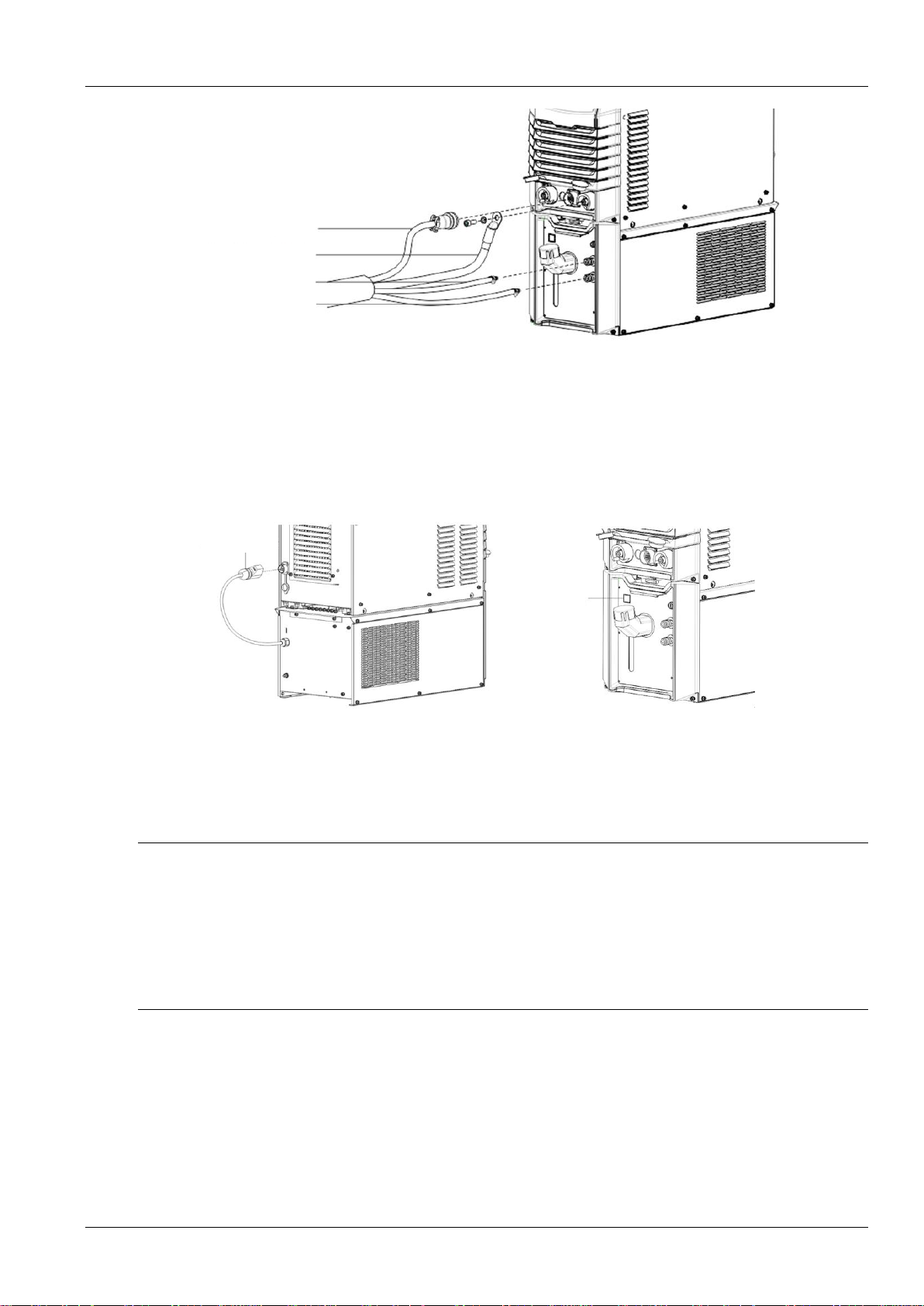
2.5.1 Connecting the Welder
Firmly connect the connector of the welding power cable to the positive pole of the welder. Firmly
connect the plug of the wire feeder control cable to the power jack of the welder. See Figure 2-1.
6 Chapter 2 Installation and Cable Connection
Full Digital IGBT CO2/MAG/MIG Multifunctional Inverter Welder User Manual
Plug of the wire feeder
control cable
Connecter of the welding
power cable
Water inlet tube
Water outlet tube
Figure 2-1 Schematic diagram of connecting the welder
2.5.2 Connecting the Water Tank
Connecting the Water Tank Power Cable
Connect one end of the water tank power cable to the welder and the other end to the water tank power
jack. See Figure 2-2.
Water tank
power switch
Water tank
power plug
Figure 2-2 Schematic diagram of connecting the water tank power cable
Water Tube Connection
Connect the water inlet tube and water outlet tube in the cable bundle to the water inlet tube and water
outlet tube of the water tank respectively. See Figure 2-1.
Safety Warning
1. When using the water tank, turn on the power switch of the water tank and enable the
air-cooling/water-cooling function on the water tank panel. Otherwise, the welding torch may get burnt.
2. The water tank power supply has a high voltage, which is AC 380 V. Disconnect the power supply before
connecting cables; failing to do so may lead to electric shock.
3. When the ambient temperature is below 10°C, use antifreeze dedicated to the water tank to prevent water tank
damages.
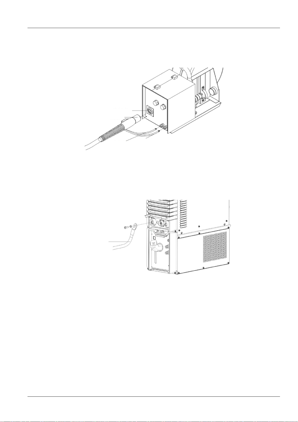
2.5.3 Connecting the Wire Feeder
1. Loose the fastener at the rear end of the wire feeder.
2. Use a but to firmly connect the welding power cable to the threaded rod on the wire feeder mother
board.

Chapter 2 Installation and Cable Connection 7
Full Digital IGBT CO2/MAG/MIG Multifunctional Inverter Welder User Manual
3. Rotate the plug of the wire feeder control cable to connect the cable firmly to its jack. See Figure
2-3.
Gas tube
Plug of the wire feeder control cable
Welding power cable
Water outlet tube
Water inlet tube
Fastener
Figure 2-3 Schematic diagram of connecting the wire feeder
2.5.4 Connecting the Gas Supply System
Note
1. If the protective atmosphere containing CO2is adopted, use a carbon dioxide heating regulator.
2. The gas tube must be connected firmly to the wire feeder and gas meter to prevent gas leakage.
Connect one end of the gas tube to the gas tube connector on the wire feeder and tighten the gas tube hose
clamp. Connect the other end to the gas tube connecter of the gas meter and tighten the hose clamp. See
Figure 2-4.
Gas tube connector of
the gas meter
Gas tube connector of
the wire feeder
Figure 2-4 Schematic diagram of connecting the gas tube
2.5.5 Connecting the Welding Torch
Note
When installing the welding torch, check whether the welding torch contains a wire inching hose and whether the
components are correct.
8 Chapter 2 Installation and Cable Connection
Full Digital IGBT CO2/MAG/MIG Multifunctional Inverter Welder User Manual
Install the welding torch to the welding torch jack on the wire feeder. Connect the water outlet tube and
water inlet tube of the welding torch to the water outlet tube and water inlet tube of the wire feeder
respectively. See Figure 2-5.
Jack on the wire
feeder
Plug of the welding
torch
Water outlet
tube of the
welding torch
Water inlet tube
of the welding
torch
Figure 2-5 Schematic diagram of connecting the welding torch
2.5.6 Connecting the Welding Power Cable (Ground Cable) of the Workpiece
Firmly connect one end of the welding power cable (ground cable) of the workpiece side to the negative
pole output terminal and the other end to the workpiece. See Figure 2-6.
Welding power
cable of the
workpiece side
Figure 2-6 Schematic diagram of connecting the welding power cable (ground cable) of the workpiece
2.5.7 Connecting the Power Cable on the Power Input Side (AC 380 V)
1) Turn off the power switch of the distribution box (user equipment) and remove the input terminal
cover.
2) Firmly connect one end of the input power cable to the power input terminal using the power cable
clamp. Connect the ground cable to the M6 grounding threaded rod on the housing of the welder. See
Figure 2-7.
3) Install the input terminal cover.
4) Connect the other end of the input power cable to the output terminal of the power switch of the
distribution box.

Chapter 2 Installation and Cable Connection 9
Full Digital IGBT CO2/MAG/MIG Multifunctional Inverter Welder User Manual
Input terminal cover
Power switch of
the distribution box
Input power cable
clamp
Input power cable
Ground cable
Figure 2-7 Schematic diagram of connecting the power cable on the power input side
Note
The welder has no special requirement for the phase sequence of the three phase power supply from the grid. The
cross-sectional area of the power cable for Artsen CM350 must be at least 10 mm2. The cross-sectional area of the
power cable for Artsen PM/CM400 and Artsen PM/CM500 must be at least 16 mm2.
10 Chapter 3 Function Description and Usage
Full Digital IGBT CO2/MAG/MIG Multifunctional Inverter Welder User Manual
Chapter 3 Function Description and Usage
3.1 Welding Preparation
a) Verify that the welder cables are connected properly.
For details, see Section 2.5 "Electric Connections."
b) Install the welding wire.
See the User Manual for CO2/MAG/MIG Wire Feeder .
c) Turn on the power switches.
Turn on the power switches of the welder and water tank.
d) Verify that the parameters on the control panel are set correctly.
When using the water-cooled welding torch, enable the air-cooling/water-cooling function on the
control panel. For details, see Section 3.2.4 "Air-Cooling/Water-Cooling."
3.2 Function Description and Usage
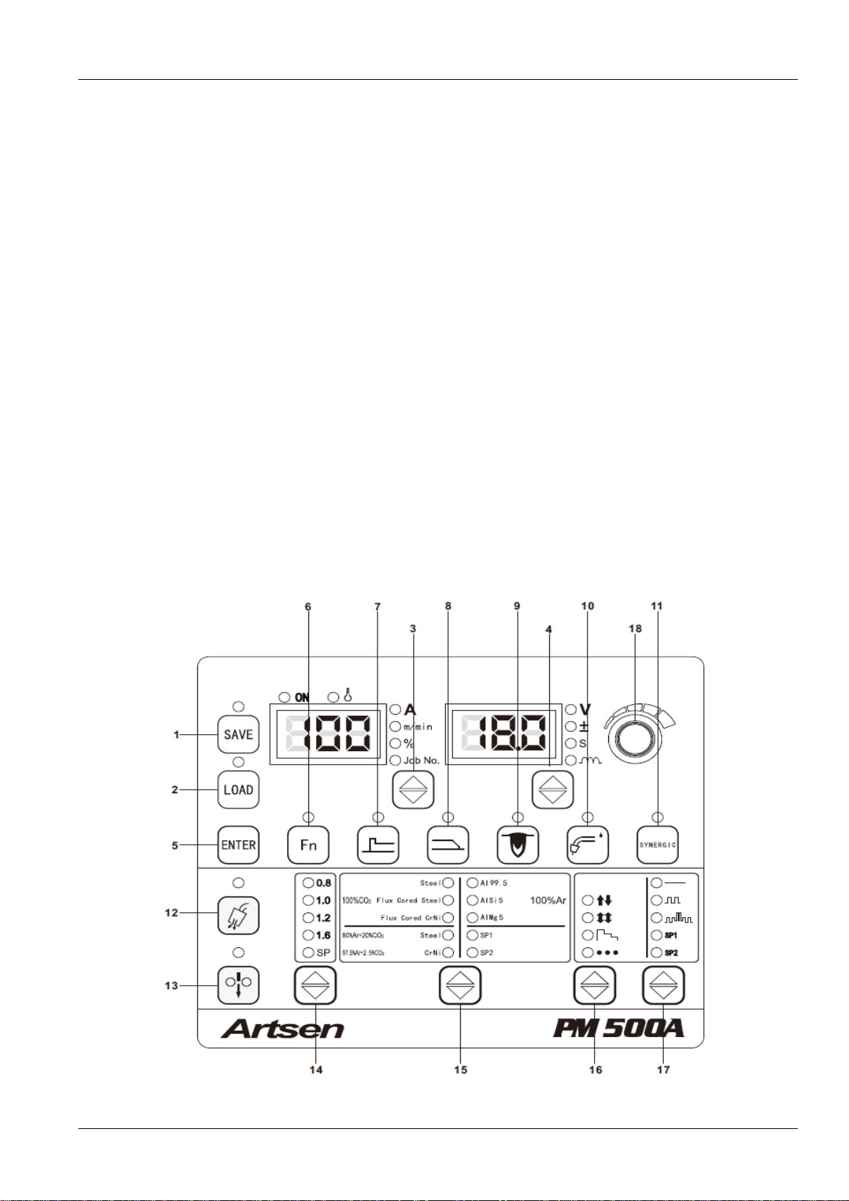
Figure 3-1 shows the functions of the control panels of the welder and wire feeder.
The serial numbers on the control panel of the welder correspond individually to a button serial number in
error codes.

Chapter 3 Function Description and Usage 11
Full Digital IGBT CO2/MAG/MIG Multifunctional Inverter Welder User Manual
Current
adjusting knob
Voltage
adjusting knob
Welding
torch jack
Water outlet
Water inlet
Detect gas
Inch wire
Current Voltage
Figure 3-1 Description of functions of the control panes of the welder and wire feeder
Table 3-1 Function description
SN
Button
Function
1
SAVE
Saves selected welding parameters.
2
LOAD
Loads saved welding parameters.
3
Switch among the options
of the left LED
Changes the current, wire inching speed, percentage, and channel number.
4
Switch among the options
of the right LED
Changes the voltage, corrected voltage value, time parameter, and electric arc dynamic.
5
ENTER
Confirms and locks parameters.
6
Fn
Sets internal menu parameters.
7
Starting arc parameters
Views starting arc parameters, including the current, wire inching speed, and voltage for
starting arc, adjustable percentage of starting arc, corrected voltage for starting arc,
starting arc generation time, and arc dynamic.
8
Ending arc parameters
Views ending arc parameters, including the current, wire inching speed, and voltage for
ending arc, adjustable percentage of ending arc, corrected voltage for ending arc, ending
arc generation time, and arc dynamic.
9
Fusion depth control
Ensures consistent fusion depth when wire stick-out is changed.
10
Air-cooling/Water-cooling
Switches between the air-cooling and water-cooling functions.
11
SYNERGIC
In synergic setup mode, the system sets the voltage according to the current.
In the manual setup mode, the current and voltage are set independently.
This manual suits for next models
9
Table of contents
Popular Welding System manuals by other brands

Lincoln Electric
Lincoln Electric IDEALARC IM402-B Operator's manual

Cutlass Fasteners
Cutlass Fasteners CLASSIC+CD manual

Northern Industrial
Northern Industrial Flux Core 125 Quick setup guide

Lincoln Electric
Lincoln Electric OUTBACK 145 Operator's manual

Chicago Electric
Chicago Electric 6271 Assembly and operating instructions

Stahlwerk
Stahlwerk AC/DC WIG241P user manual


