PRO WELD INTERNATIONAL AG-900 Manual
OPERATION/MAINTENANCE
OPERATION/MAINTENANCEOPERATION/MAINTENANCE
OPERATION/MAINTENANCE
MANUAL
MANUALMANUAL
MANUAL
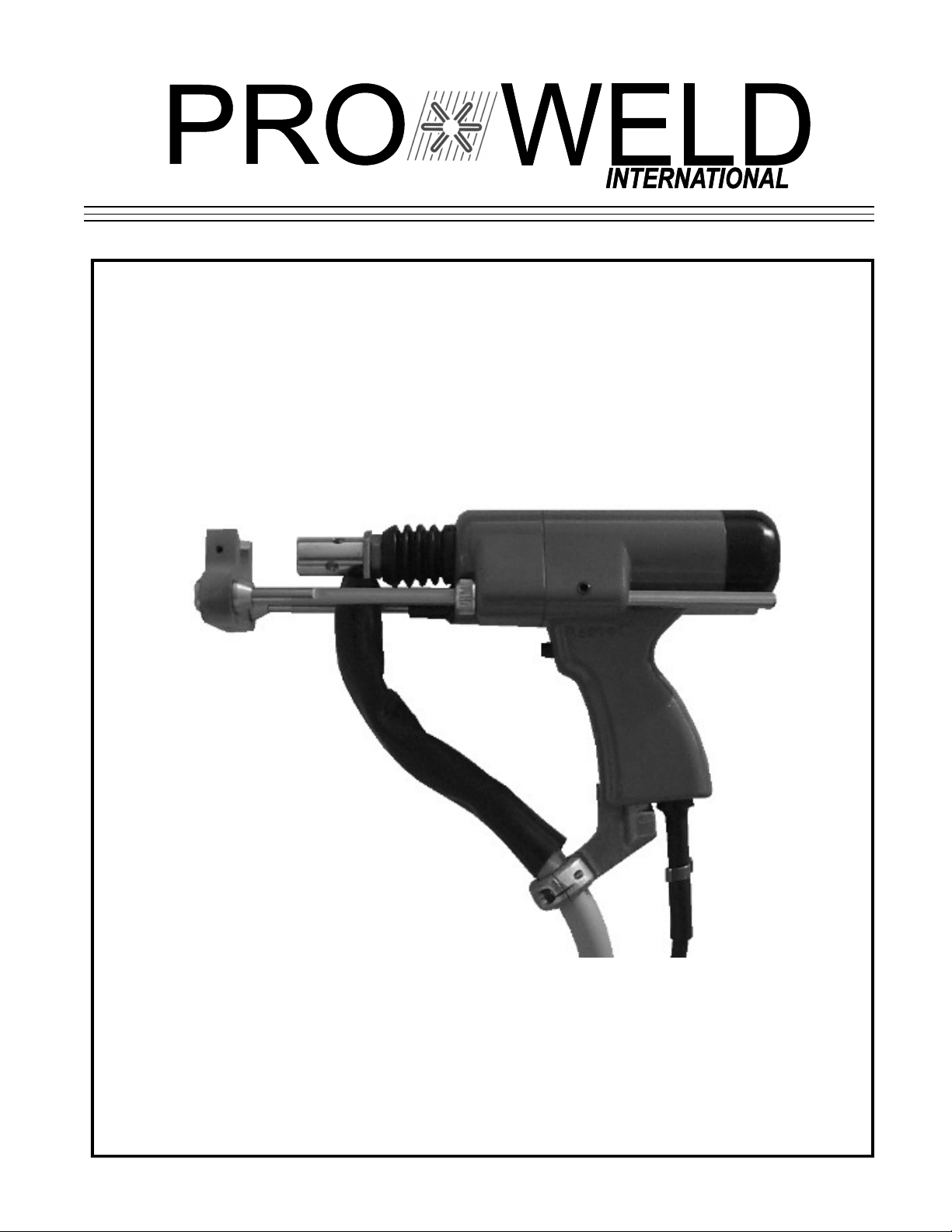
H.D. ARC GUN
H.D. ARC GUNH.D. ARC GUN
H.D. ARC GUN
AG
AGAG
AG-
---900
900 900
900


AG-900
PRO WELD
TABLE OF CONTENTS
1.0 INTRODUCTION........................................................................................ 1
2.0 WARRANTY..........................................................................................…... 1
3.0 SUGGESTED SAFETY PRECAUTION................................................... 1
4.0 GENERAL DESCRIPTION........................................................................ 2
5.0 UNPACKING................................................................................................ 2
4.0 GUN SET-UP................................................................................................. 3
7.0 WELD TEST AND INSPECTION............................................................. 7
7.1 WELD TEST................................................................................................. 7
7.2 WELD INSPECTION.................................................................................. 7
7.3 CAUSES OF POOR OR ERRATIC WELDS...............…...............…….. 7
7.4 TROUBLE SHOOTING POOR WELDS.................................................. 9
8.0 MAINTENANCE.......................................................................................... 9
8.1 WELD CABLE REPLACEMENT............................................................. 9
8.2 CONTROL CABLE REPLACEMENT...............................................….. 9
8.3 DISASSEMBLY OF GUN………………………....................................... 10
8.4 GUN MAINTENANCE……………..........................................................… 10
8.5 RE-ASSEMBLY............................................................................................ 11
PARTS LIST GUN ASSEMBLY ARC STD. HD...................................... 12
9.0 TROUBLE SHOOTING GUIDE................................................................ 14
PRO WELD
AG-900
AG-900
PRO WELD
PRO WELD
AG-900
AG-900
PRO WELD

PRO WELD
AG-900
1.0 INTRODUCTION
Your new stud welding equipment is constructed
of the finest components and material available.
Used properly, this equipment will give you years
of profitable, efficient service.
The system incorporates the latest in engineering
advances, for complete reliable welding of mild
steel, stainless steel, and aluminum.
2.0 WARRANTY
The electrical and mechanical components of the
stud welder are thoroughly performance inspected prior
to assembly in the welder. The assembled welder is
completely performance checked. The welder is
delivered to you in functional electro-mechanical
condition.
All parts used in the assembly of the welder and
its accessories are fully warranted for a period of 1
YEAR from the date of delivery. In addition, the
welding capacitors are warranted for a period of 1
YEAR from the date of delivery. The printed circuit
boards used in all proweld equipment are warranted for
a period of 3 years.
Under the warranty, the manufacturer reserves
the right to repair or replace, at their option, defective
parts which fail during the guarantee period. Notice of
any claim for warranty repair or replacement must be
furnished to the manufacturer by the purchaser within
ten (10) days after the defect is first discovered. The
manufacturer does not assume any liability for paying
shipping cost or any labor or materials furnished where
such cost are not expressly authorized in writing.
The manufacturer does not warrant any parts or
accessories against failures resulting from misuse,
abuse, improper installation, maladjustment, or use not
in accordance with the operating instructions furnished
by the manufacturer. The warranty is valid only when
studs are purchased from sources approved by the
manufacturer or are of identical specifications to the
manufacturer’s
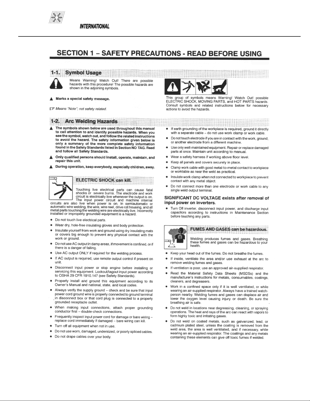
3.0 SUGGESTED SAFETY PRECAUTIONS
In any welding operation, it is the responsibility of the
welder to observe all safety rules to insure his or her
personal safety and to protect those working in the area.
Reference is directed, without endorsement or
recommendation, to ANSI Z49.1, Safety in Welding and
Cutting, and to AWG Publication A6-66, Recommended
Safe Practices for Gas-Shielded Arc Welding.
1. Always treat electricity with respect. Under open
circuit conditions, the welding machines output voltage
may be dangerous.
2. Don’t work on live circuits or conductors. Disconnect
the main power before checking the machine or
performing any maintenance.
3. Be sure the welding machine cabinet is properly
grounded to a good electrical ground. Consult local
electrical codes.
4. Never operate a welder in the rain, or operate a welder
while standing in water. Avoid wearing wet or sweaty
clothes when welding.
5. Don’t operate with worn or poorly connected cables,
and don’t operate the weld gun with loose cable
connections. Inspect all cables frequently for insulation
failures, exposed wires, loose connections and repair as
needed.
6. Don’t overload welding cables or continue to operate
with over heated cables.
7. Don’t weld near flammable materials or liquids in or
near the area, or on ducts or pipes carrying explosive
gases.
PAGE 1
AG-900
PRO WELD
8. Don’t weld on containers which have held
combustible or flammable materials, or on
materials which give off flammable or toxic
vapors when heated.
9. Be sure to provide for proper ventilation
when welding in a confined area.
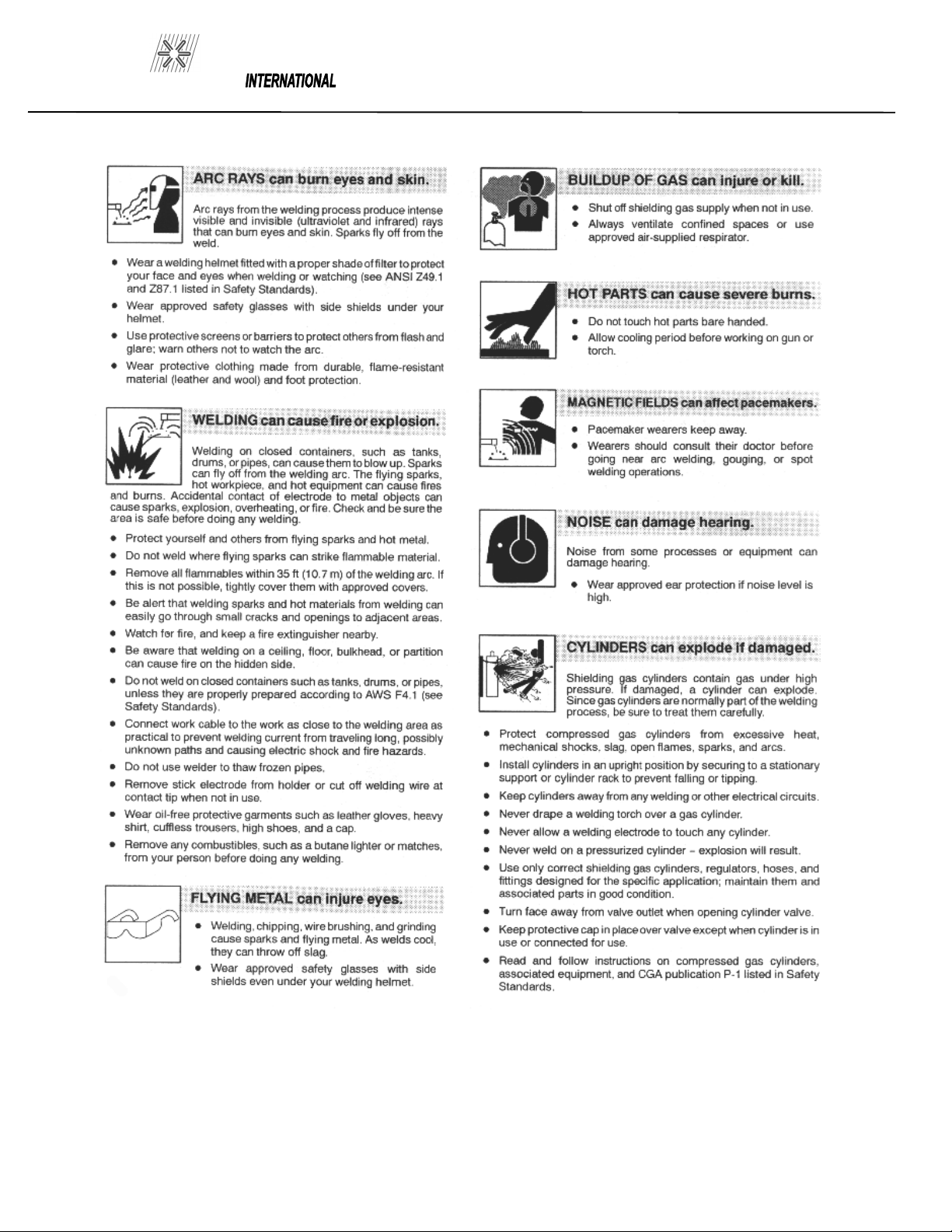
10. Never look at the electric arc without
wearing protective eye shields.
11. Always use the proper protective clothing,
gloves, etc.
12. Never strike an arc when near a bystander
who is unaware of the danger of ultraviolet
light to their eyes.
4.0 GENERAL DESCRIPTION
WELD GUN - STANDARD ARC HEAVY DUTY
(Part No. 300-0900)
A shaped to the hand, semi automatic stud welding
tool. Welds any length stud with a diameter range of
5/8 through 1-1/4 inches. Refer to figure 4-1 for
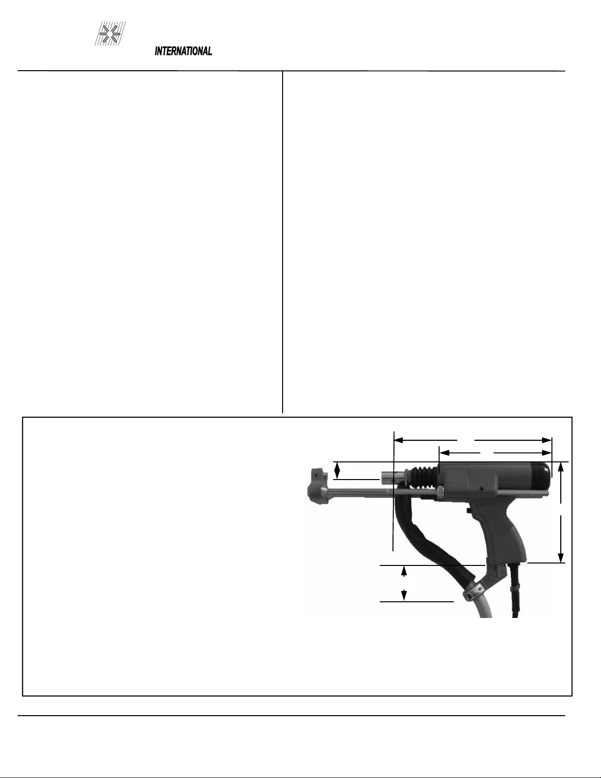
weight and size specifications.
5.0 UNPACKING
There is very little to do when unpacking your ARC
Stud Welding gun. Your Stud Welder comes
complete with all the accessories and tool required
for set-up, adjustment, and maintenance. Aside from
the correct chuck, ferrule grip, and any special
accessories required for your application your ARC
weld gun is ready for hook-up to a Pro Weld power
source.
Weight (includes standard legs,
foot, and 1/0 cables)............. 6.2 pounds...2.8 kg
Typical working weight gun plus
4 feet of unsupported 4/0 cables ..9 pounds...4.2 kg
Shipping weight of gun plus
approximately 8 feet of
4/0 cable and connectors....... 13.5 pounds...6.1 kg
Note: Chuck and ferrule grip are not standard and
must
be ordered separately.
Figure 4-1 Standard ARC HD Weld Gun
9.5
7”
6”
2”
1”
PAGE 2

PRO WELD
AG-900
6.0 GUN SET-UP
The standard gun set-up is used for welding the
majority of applications. It consists of the standard
adjustable face plate, two legs, a foot, chuck adapter,
chuck, and spring for your specific stud size.
The following is a step by step explanation of the
correct way to set up the gun. (Refer to Figure 6-1)
1. A different, and correctly sized, chuck and ferrule
grip are needed for each different stud diameter and
style that will be welded. The appropriate chuck, or
stud holder, is inserted into the tapered chuck adapter
and tapped lightly to insure a tight fit. The ferrule
grip is inserted in the hole in the foot and secured
with the locking screws to hold it in place.
2. Studs must NOT bind or hang up on the foot,
ferrule grip, or ferrule during the entire stud welding
process. To assure this, the foot/ferrule arrangement
must be centered in relation to the stud to be welded.
To assure centering, loosen the locking screws that
hold the foot to the legs. Place a stud in the chuck
and a ferrule in the grip. With the locking screw
Figure 6-1 GUN SET-UP
loosened, the foot will move freely in all directions.
Adjust the foot so that the stud is centered in the
ferrule and no contact occurs between the stud and the
ferrule during retraction or forward plunge of the stud.
Tighten the locking screws after centering the stud.
3. The “Plunge Length” is the amount of stud exposed
beyond the ferrule during initial set-up. Set the plunge
by loosening the leg adjusting screws and moving the
foot until the stud extends 1/8” to 3/16” past the end of
the ferrule. Tighten the leg adjusting screws after
setting the plunge and re-check centering to be sure
the stud is aligned properly in the ferrule.
4. The lift height, which determines the arc length,
has been pre-set at the factory and will automatically
lift and plunge the stud during the welding process.
“Lift” is the distance the gun will raise the stud above
the welding surface during the weld. This distance
governs the voltage and the arc. Improper lift will
cause unsatisfactory welds.
To measure the lift, turn the stud welding unit on and
set the timer to maximum time. (On certain units there
may be a Lift Check switch available, and in these
cases this switch can be used to check lift.) Trigger
the gun in the air or on a non-grounded or insulated
surface, to observe the lift cycle. Measuring the
distance the stud or gun mechanism moves equals lift.
Usually this can be easily done by visual observation
or simple measurement against a static reference point
(i.e. the ferrule properly seated in the ferrule grip).
PAGE 3
AG-900
PRO WELD
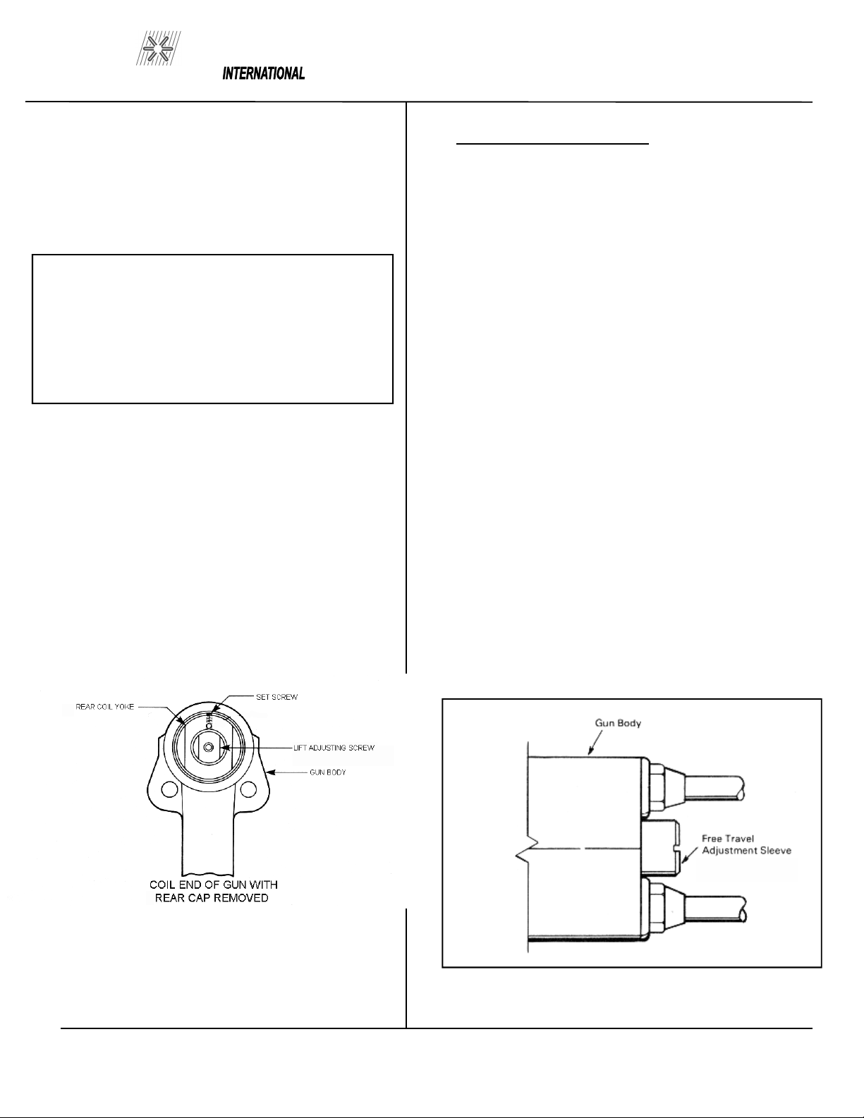
When it does become necessary to adjust the lift,
you do so by removing the rear cap from the gun.
This will expose the rear coil choke assembly, the
set screw, and the lift adjusting screw (Refer to
Figure 6-2).
Loosen the set screw.
To increase lift: turn the adjusting screw out
(counter clockwise).
To decrease lift: turn the lift adjusting screw in
(clockwise).
Once the lift has been set, tighten the set screw and
replace the rear cap.
Figure 6-2 LIFT ADJUSTMENT
RECOMMENDED LIFT SETTINGS
Stud Base Dia. Lift Setting
Less than 1/2” 3/32”
1/2” through 3/4” 3/32”
Greater than 3/4” 3/32-1/8”
5. Adjustment of Free Travel
With the free travel adjustment sleeve screwed fully in,
(clockwise) there is no free travel when the plunge
length plus the lift height adds up to be less than 7/16
inch (the maximum stroke of the damper). To increase
the free travel, back out (counterclockwise) the free
travel adjustment sleeve (refer to figure 6-3).
Each full turn provides .062 inch of additional free
travel.
The following recommendations are for normal stud
welding applications.
For studs with a weld base of 1/2 inch dia. Or under back
out the free travel adjustment sleeve 2 turns.
For studs with a weld base of 5/8 to 3/4 inch dia. Back
out the free travel adjustment sleeve 2-3 turns
Larger diameter studs require increased free travel to
prevent excessive weld fillet spatter.
Figure 6-3
PAGE 4

PRO WELD
AG-900
6. Make sure that the cables are connected to the
power source (standard set-up is straight polarity –
Negative to controller, or gun, and Positive, ground
cable, to work surface).
7. Turn on the power supply and adjust the current and
time for the weld base diameter of the fastener to be
welded.
8. Place the gun, loaded with the stud and ferrule,
squarely against the ground work surface. The main
spring in the gun will take up the “plunge length” and
the ferrule will seat against the base plate.
9. Pull the trigger holding the gun completely still as
above. The gun will lift the stud from the base plate
and draw an arc. The end of the stud and the adjacent
metal of the base plate will be melted by the weld arc.
The gun will then plunge the stud into the molten pool,
extinguishing the arc, to end the controlled portion of
the weld cycle.
DO NOT MOVE THE GUN DURING THE WELD
CYCLE.
10. After the controlled weld cycle, allow the molten
metal to solidify briefly with the work surface to assure
completion of the cycle (about an extra second holding
“still” after the weld is usually sufficient).
11. Remove the gun from the work by lifting straight
away from the welded stud (this will assure better life
to the gun’s expendable accessories). The ferrule may
now be removed by breaking it away from the welded
stud to allow inspection of the weld results. After
inspection of sample welds the gun can be adjusted, as
per the steps in this procedure, for optimum results.
PAGE 5

AG-900
PRO WELD
The stud is pressed
against the base
Lifting rod assy.
moves freely to take
up plunge.
Main spring com-
presses
Gun solenoid is
energized
Armature assembly is
pulled back to built against
Lift adjusting screw.
The lifting hook on the
Armature assembly
cocks
The gun is in the
The timer times out.
Gun solenoid is
de-energized
Lifting ring is uncocked by
lifting ring spring.
Armature assembly is
returned to relaxed state
by armature return spring.
Lifting rod is no longer engaged by
lifting ring and returns to relaxed
state. The main spring plunges
the stud against the base plate.
Figure 6-4 GUN OPERATION FLOWCHART
Gun trigger is
pulled
PAGE 6

PRO WELD
AG-900
7.0 WELD TEST AND INSPECTIONS
Testing of weld quality beyond visual inspection
varies with stud characteristics. Refer to AWS
(American Welding Society) Structure Welding
Code AWS D.1-Rev. 1-76. Welding procedures
are covered in Sections 4.28 and 4.29. Weld test
and inspection is covered in Section 4.30,
paragraphs 1 through 4. (American Welding
Society, Inc., 2501 N.W. 7th, Street, Miami, Fla.
33125).
7.1 Weld Test
A. Bend Test
A bend test may be used to test weld results if the
stud may be destroyed. This is usually done with a
bending tool (a hollow pipe with an inside diameter
just large enough to fit over the diameter of the
studs). The bend tool is placed over the stud, down
to the base material. The stud is then be repeatedly
bent away from its axis until failure occurs.
B. Torque Test – Threaded Studs
A torque test may be used on threaded studs. The
stud is twisted to the point of failure. A twisting
tensile load is applied by using a collar, washer and
nut. A bend test can be used on threaded studs as
well.
C. Test Results
In an acceptable weld, failure will occur in the stud
material or tear out of a thin base plate. Failure in
the weld requires adjustment of procedure, weld
time and current setting.
7.2 Weld Inspection
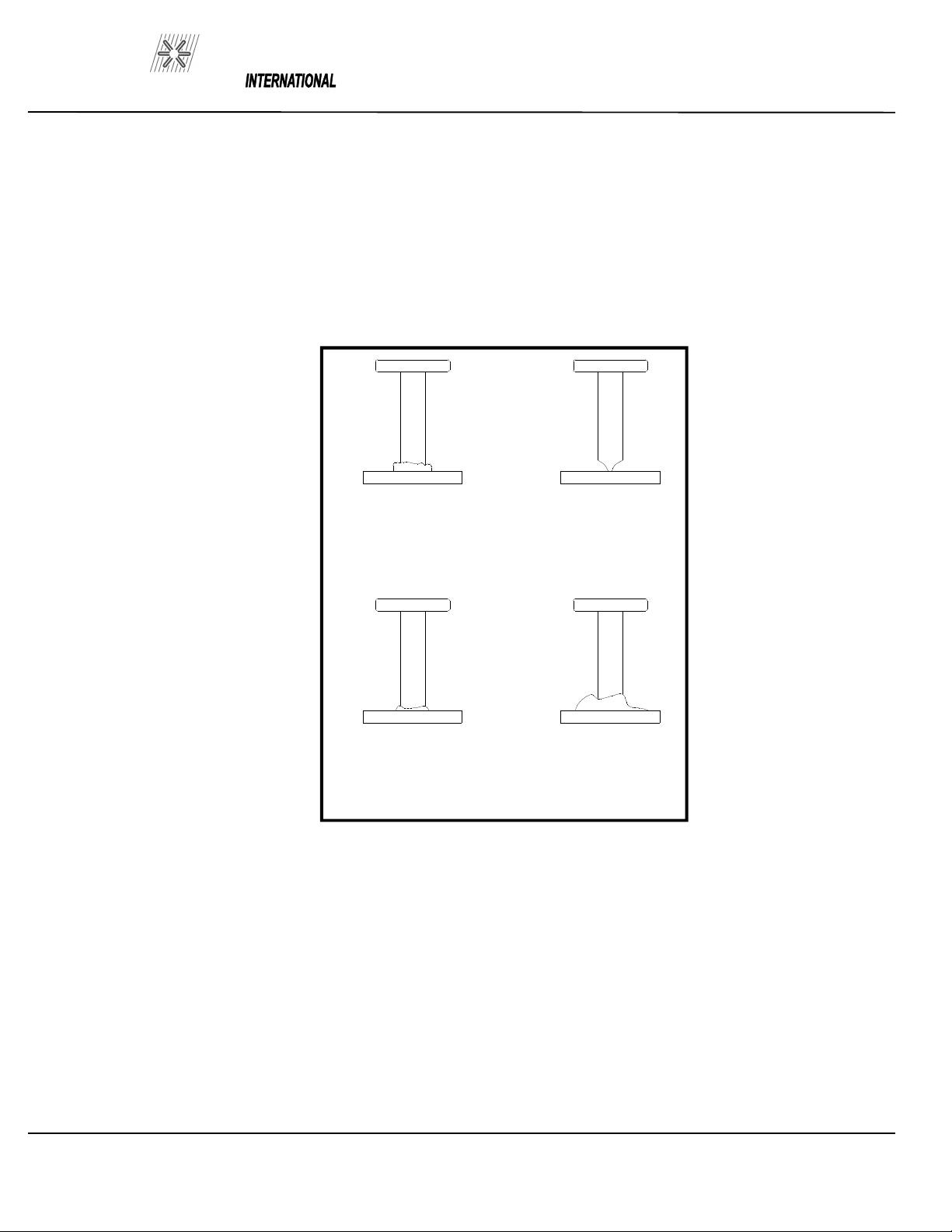
Weld quality can be visually inspected. Refer to
Figure 7-1 as a reference to the quality of the weld.
7.3 Causes Of Poor Or Erratic Welds
1. Loose chuck. Does not grip stud tightly.
(replace) Not enough engagement of stud to
chuck. (Adjust stop)
3. Poor surface condition of base material, excessive
oil, grease, rust, etc. (Clean)
4. Weld current or weld time setting too low or too
high. (Adjust to diameter of studs)
5. Broken or loose cables. (Repair)
6. Dirt in gun. (Clean)
7. Incorrect polarity. (Cables hooked-up wrong)
8. Cables too closely coiled.
9. Arc blow is evidenced by “one side” welds. In
severe cases there will be no melting under one
edge of flange while the opposite side is gouged
out or appears excessively hot. The principle
cause of arc blow is a magnetic field induced by
the current flow during the weld. It occurs most
often on long, narrow strips of metal or near
edges of sheets or plates. In some cases, a
change in grounding positions, or two ground on
the work piece, one at each end or edge of work,
will correct the problem
PAGE 7
AG-900
PRO WELD
Figure 7-1 WELD INSPECTION
GOOD STUD WELD
A good full fillet
STUD HANG UP
Adjust foot to
insure the stud is
centered in the
ferrule
COLD WELD
Increase weld
current and/or
weld time
HOT WELD
Reduce weld
current and/or
weld time
PAGE 8

PRO WELD
AG-900
For assistance in sever cases, contact your local
sales representative.
10. Incorrect plunge setting. (Adjust to proper
setting)
11. Incorrect lift setting. (adjust to proper
setting)
12. Poor stud quality.
13. Arc shield so far off center from weld end
of stud that stud catches on edge of arc shield
and is not driven back into pool of molten
metal.
7.4 Trouble Shooting Poor Welds
1. Weld Too Hot
A) Decrease weld time.
B) Decrease weld current.
C) Increase stud protrusion.
2. Weld too Cold
A) Increase weld time.
B) Increase weld current.
C) Decrease stud protrusion
3. Arc Blow
A) Use double grounds.
B) Ground too close or not spaced evenly.
4. Hang-Up
A) Re-align arc shield
8.0 MAINTENANCE
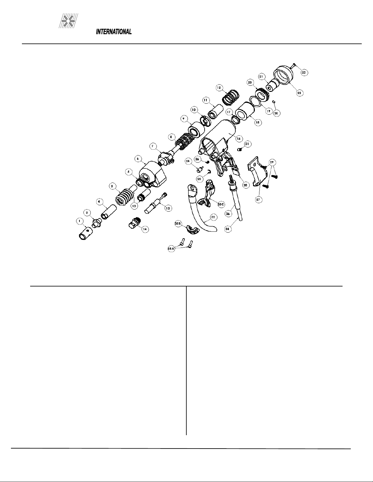
(Refer to HD ARC GUN EXPLODED VIEW in Section 10
of this manual for location for “()” numbers noted in this
text.)
8.1 Weld Cable Replacement
Remove legs by loosening set screws (31). Remove chuck
and adapter (1). Take the weld cable (32) off connector
stud (2).
Loosen screws (35A) in cable guide assembly (35) and
remove the clamp (35B). Remove the tape which holds the
control cable to the weld cable.
When replacing the weld cable, it should be clamped 8-1/4”
from the center of the lug and untwisted to relieve the
stranding. Failure to do this will cause undo restriction on
the gun workings. (Re-install rubber sleeve on end of weld
cable.)
With the control cable (34) in front of the weld cable, tape
together 4 1/2” below the bottom of the extension bar. This
will provide strain relief. Tape every 12”
8.2 Control Cable Replacement.
Remove tape holding control cable and weld cables
together. Remove three screws (29) in handle (27).
Disconnect the two wires from switch (28) and the two
wires from the gun coil leads (18).
Install the new cable and re-connect wires to trigger and
gun coil.
Tape control cable to front of weld cable 4-1/2” below
extension bar and tape every 12”.
PAGE 9
AG-900
PRO WELD
8.3 DISASSEMBLY OF GUN
Step By Step Gun Disassembly. Refer to
Exploded view.
Loosen leg set screws (31), remove foot and leg
assembly and unscrew chuck adapter (1).
Remove weld cable (32) from connector stud
(threaded hex shaft adapter) (2) and remove
dust seal bellows (3).
Unscrew end cap nuts (13), remove front cover
(6), plunge damper assembly, and balance of
lifting rod assembly as a unit.
Remove the main spring (8) and lift stop
housing (9), lifting ring (10), moveable core
(11) and core spring (12) from gun body (16).
Remove screw (23) and rear cover (22).
Loosen set screw and unscrew adjustable core
(21). Do not unscrew, loosen or remove rear
coil yoke (20) or gun coil (18).
8.4 Gun Maintenance
If the gun motion becomes sluggish or erratic the
gun should be disassembled, cleaned, and
lubricated.
A. Disassemble the gun as described. Blow or
wipe the gun body and parts clean.
B. The inside diameters of adjustable core screw,
the lifting ring and mating diameters on the lifting
rod should be carefully examined for wear or rust.
Although the lubrication should prevent any
oxidation on these surfaces, if they reveal signs of
dirt or a dull reddish brown stain, clean and polish
with a fine abrasive paper, grip #0 or finer.
C. Lubricate lifting rod surface with a thin coat of
high temperature bearing grease, Lubricate M-24-
M or equivalent.
PAGE 10

PRO WELD
AG-900
8.5 Re-assembly Of Gun
A. Step By Step Re-assembly of Gun – Refer to
Exploded View.
1. Install the lifting ring, onto the movable core
assembly , by inserting the hook through a “window”
of the lifting ring with the flat side of the ring
towards the movable core assembly. Insert the
assembled lifting ring (10) and movable core (11) in
the lifting stop housing (9).
2. Place this lifting assembly into the gun body (16).
Replace the main spring (8) in the gun body.
3. Re-install the plunge damper assembly (15) by
extending the piston rod of the plunge damper. Insert
the plunge damper into the front cover (6). Screw the
damper cover (14) in place.
Inspect and replace if necessary the front bearing (5)
inside the front cover.
5. Install lifting rod (7) through rear of front cap (6).
Engage the hook of the lifting rod on the spool of the
plunge damper. Attach the shaft extension (4) to the
lifting rod.
6. Re-install the front cap and lifting rod into gun by
inserting the lifting rod through main spring and lifting
assembly. Secure front cover with cover nuts (13).
7. Install bellows (3) over shaft extension. Install
connector stud (2) onto shaft extension .Install weld
cable (32) onto connector stud and secure with chuck
adapter (1).
8. Re-install foot and leg assembly. Adjust the
plunge, free travel and lift.
9. Replace rear cap (22) and secure with screw (23).
PAGE 11

AG-900
PRO WELD
PAGE INTENTIONALLY LEFT BLANK
PAGE 12
PRO WELD
AG-900
PAGE 13
ITEM DESCRIPTION PART NO.
1 CHUCK ADAPTOR 033-505
2 CONNECTOR STUD 033-506
3 BELLOWS 301-0018
4 SHAFT EXT. 033-507
5 BEARING 033-491
6 FRONT CAP . 303-0003
7 LIFTING ROD 303-0006
8 SPRING, MAIN
301-0017
9 LIFT STOP HOUSING 301-0019
10 LIFTING RING 301-0014
11 MOVEABLE CORE 301-0013
12 SPRING, CORE 301-0012
13 NUT, END CAP 033-482
14 DAMPER COVER 303-0008
15 DAMPENER 301-0021
16 GUN BODY 302-0001
17 COIL YOKE BEARING 301-0009
18 COIL, GUN 105-0024
19 WAVE WASHER 102-0117
ITEM DESCRIPTION PART NO.
20 REAR COIL YOKE 301-0016
21 LIFT ADJ. SCREW 301-0008
22 REAR CAP 033-493
23 SCREW,#8-32 X 3/4 PAN HD. 037-521
24 TRIGGER BUTTON 302-0013
25 SNAP RING 302-0023
26 TRIGGER SPRING 302-0016
27 HANDLE COVER 302-0009HD
28 TRIGGER SWITCH 302-0010
29
SCREW, #10-32 X 1/2 OVAL HD
115-0009
30 SCREW, #8-32 X 1/4 SET 115-0010
31 SCREW, 5/16-18 X 3/8 SET 037-557
32 WELD CABLE ASSY 044-059
34
CONTROL CABLE ASSY
302-0028
35 CABLE GUIDE ASSY 303-0009
35A SCREW, #10-32 X .625 SHCS 115-0012
35B CLAMP, CABLE GUIDE 303-0009-2
35C
SUPPORT, CABLE GUIDE
303-0009-1
N/S WELD CABLE BOOT 044-059-1
36
CONTROL CABLE BOOT
036-897-1
Table of contents
Other PRO WELD INTERNATIONAL Welding System manuals

Popular Welding System manuals by other brands


Hobart Welding Products
Hobart Welding Products AirForce 375 owner's manual

GF
GF MSA 330 instruction manual

Hakko Electronics
Hakko Electronics FX-888D instruction manual

Abicor Binzel
Abicor Binzel ABIPLAS WELD 100 W operating instructions

EWM
EWM Taurus 355 Basic TDM operating instructions

Thermal Dynamics
Thermal Dynamics PakMaster 100 XL plus operating manual


