meibes LogoFresh Compact Manual
E]aZ]kKqkl]e%L][`fac
Jaf_kljY¿])0%<%(,0*/?]ja[`k`Yaf%L]d&#,1 (!+,*1*/)+%(%>Yp/)+%-(
ooo&e]aZ]k&\]%]%eYad2af^g8e]aZ]k&\]
Technical information for installation and operation
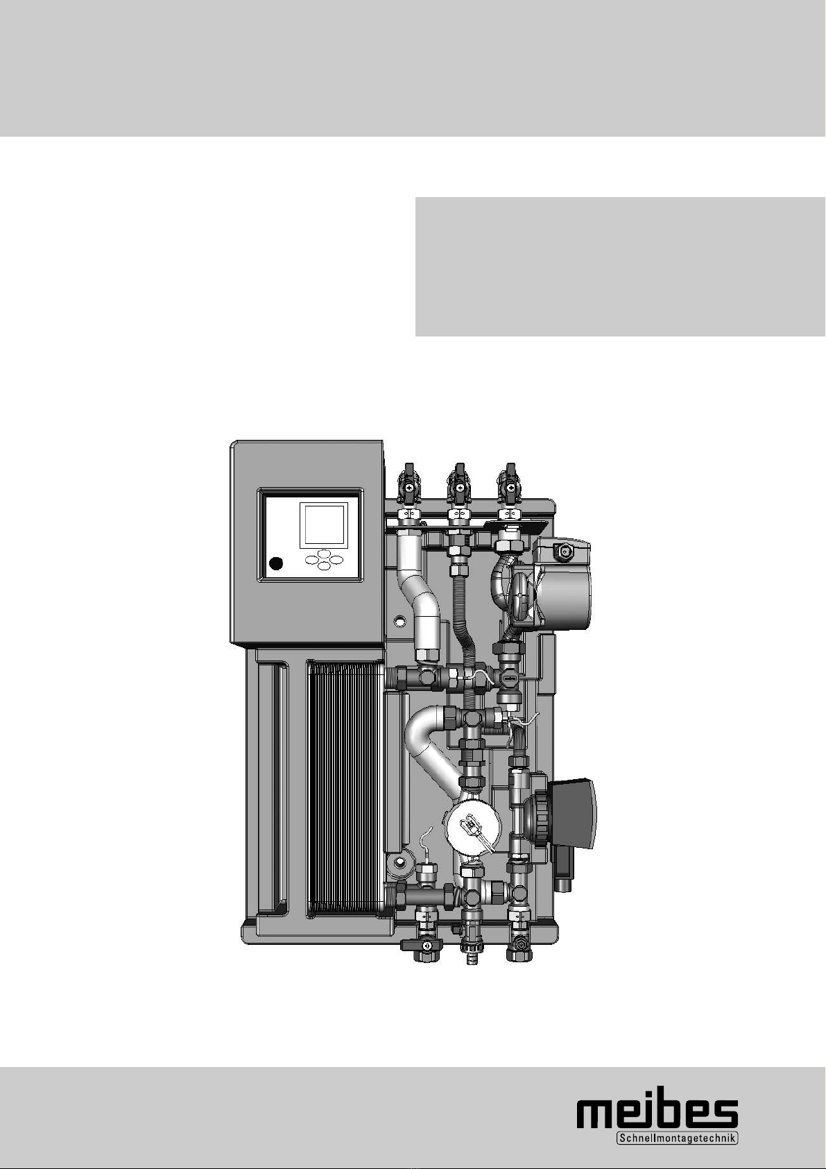
Freshwater Station
LogoFresh Compact
electronically controlled
PR 24002.123 31-03-2011 Subject to technical modifications

1
Contents
Chapter Title Page
1. Safety instructions 2
2. Technical specifications 2
2.1 Performance characteristics 3
3. Equipment and functional description 4
4. Installation 5
4.1 Hydraulic connections 5
4.2 Electrical connections 5
5. Control system 6
5.1 Display description 6
5.2 Operating keys – description 6
5.3 Control menu structure 7
5.3.1 Explanation of menu items 8
5.3.2 Information menu 8
5.3.3 Programming menu 8
5.3.4 Manual operation menu 9
5.3.5 Basic setting menu 9
6. Initial operation and system calibration 11
6.1 Flushing and filling the system 11
6.2 Controller calibration 11
6.3 Calibration procedure 11
6.3.1 Selecting pump capacity 11
6.3.2 Characteristic curve calibration 11
6.3.3 Circulation adjustment 12
6.3.4 Detailed description of characteristic curve calibration 13
7. System examples of controller settings 14
7.1 Freshwater station with circulation in a time slot and 14
with tapping detection
7.2 Freshwater station with circulation only via 14
tapping detection
7.3 Freshwater station without circulation 14
7.4 Freshwater station with reheating and/or activation 15
7.5 Increasing the domestic hot water set temperature 15
7.6 Freshwater stations as cascade connection 16
7.6.1 Initial operation and system calibration of freshwater 16
cascade
7.7 Disinfecting the hot water and circulation pipes 17
8. Releasing operating level for specialist tradesmen 17
9. Trouble-shooting 18
10. Factory setting and personal setting 19
11. Diagrams 20

2
1. Safety instructions
QThe installation and initial operation of the freshwater
station is only to be carried out by a specialist
tradesman.
QThe necessary DIN and VDE provisions are to be
observed (e.g. DIN 4751, DIN 4753, DIN 1988
and VDE 0100)
QThe provisions of local energy supply companies are
to be observed
QImproper installation as well as misuse of the
freshwater station will exclude any liability as regards
guarantee claims
Please note:
QBefore operating on the control system and the
circulating pump, they are to be switched at zero
potential as prescribed
QIn the event of a power supply interruption, the
preset values are retained
QIn the event of a power failure, the system clock
settings in the control system are retained for
approx. 24 hours
QA menu for basic settings is available which may only
be modified by a specialist tradesman. This ensures
the technical functioning and security of the system!
QAll the relevant old as well as recently enforced
provisions and norms as well as provisions and
norms not mentioned, but relevant for application in
a particular case, are to be followed
QThe legal provisions relating to the prevention of
accidents are to be followed
2.Technical specifications
Heating connections 3/4“ female 3/4“ IG
Plumbing connections 3/4” female 3/4” IG
Heating operating pressure 3 bar
Plumbing operating pressure 6 bar
Maximum allowed temperature 110°C
Controller protection class IP 54
Supply voltage 230VAC / 50Hz
Dimensions (height/length/breadth) in mm 660 x 455 x 215
3
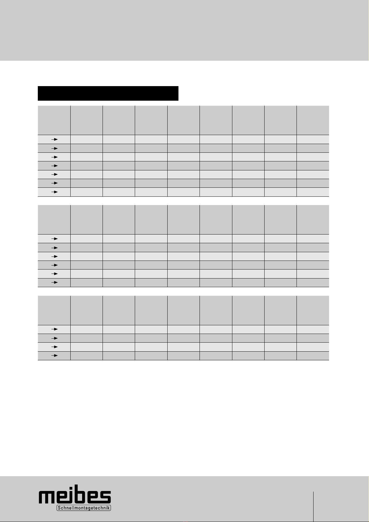
* at a sufficient domestic water system pressure
Please note: For larger drawing amounts, several freshwater stations can be constructed as a cascade. (page 16)
2.1 Performance characteristics
2.Technical specifications
Heating
cold water
K
Flow
temperature
primary
°C
Return
temperature
primary
°C
Domestic hot
water drawn
amount*
l/min
Domestc
hot water
capacity
kW
Volumetric
flow
primary
l/h
Pressure loss
primary
bar
Remaining
discharge
head
primary
bar
Pressure loss
secundary
bar
40 (10 50°C) 55 33 12 33 1350 0,24 0,15 0,14
40 (10 50°C) 60 31 17 46 1350 0,24 0,15 0,28
40 (10 50°C) 65 29 20 57 1350 0,24 0,15 0,38
40 (10 50°C) 70 27 24 66 1350 0,24 0,15 0,55
40 (10 50°C) 75 26 27 76 1350 0,24 0,15 0,69
40 (10 50°C) 80 25 30 84 1350 0,24 0,15 0,86
Heating
cold water
K
Flow
temperature
primary
°C
Return
temperature
primary
°C
Domestic hot
water drawn
amount*
l/min
Domestc
hot water
capacity
kW
Volumetric
flow
primary
l/h
Pressure loss
primary
bar
Remaining
discharge
head
primary
bar
Pressure loss
secundary
bar
50 (10 60°C) 65 40 11 39 1350 0,24 0,15 0,12
50 (10 60°C) 70 36 15 53 1350 0,24 0,15 0,22
50 (10 60°C) 75 33 19 64 1350 0,24 0,15 0,34
50 (10 60°C) 80 32 22 75 1350 0,24 0,15 0,46
Heating
cold water
K
Flow
temperature
primary
°C
Return
temperature
primary
°C
Domestic hot
water drawn
amount*
l/min
Domestc
hot water
capacity
kW
Volumetric
flow
primary
l/h
Pressure loss
primary
bar
Remaining
discharge
head
primary
bar
Pressure loss
secundary
bar
35 (10 45°C) 50 31 11 30 1350 0,24 0,15 0,12
35 (10 45°C) 55 28 17 42 1350 0,24 0,15 0,28
35 (10 45°C) 60 26 22 53 1350 0,24 0,15 0,46
35 (10 45°C) 65 25 26 62 1350 0,24 0,15 0,64
35 (10 45°C) 70 24 29 71 1350 0,24 0,15 0,80
35 (10 45°C) 75 23 33 80 1350 0,24 0,15 0,04
35 (10 45°C) 80 22 36 88 1350 0,24 0,15 1,25

4
QThe freshwater station allows for a hygienic and
energy-saving preparation of warm water via a
stainless steel plate heat exchanger. It provides fresh
hot water for one to two apartment units. The source
of supply is a storage tank with a variable tempera-
ture of 60 to 95°C. At very high storage tempera-
tures (up to 95°C) a temperature reduction of the
heat transfer media is recommended by admixture.
The primary pump P1 is controlled via block
modulation in such a way that the desired hot water
temperature is kept constant as much as possible.
For the control system to calculate the necessary
pump capacity, it uses the heat transfer media
temperature on the primary side, the inlet tempera-
ture of the cold water and the circulation on the
secondary side as well as the current flow.
QIn addition to the preparation of freshwater, the
circulation can also be activated. In the “basic
setting” menu the circulation is switched ON or
OFF.
QFor circulation, up to 3 time slots can be specified in
the “programming” menu.
QFor the stainless steel plate heat exchanger there
are three modes of operation besides the drawing of
hot water:
water temperature-cold, water temperature -hot
and water temperature-timed heating
(See 5.3.3).
3. Equipment and functional description
QAfter-run
Should water temperature-cold be selected, it is
possible to set the circulation pump at an after-run,
to allow the stainless steel plate heat exchanger
to cool down and to prevent calcification.
The after-run function is however, only possible and
meaningful outside the circulation time!
QActivating the hot water controller and reheating
With the additional T5 sensor (not included in
delivery), it is possible to put the control system in
operation only after a specified buffer temperature
has been attained. With the T5 sensor it is further-
more possible to activate a boiler for reheating via a
potential-free contact. Both functions are deactiva-
ted in the factory setting.
QDisinfection
With this function it is possible to disinfect the
circulation pipes against the danger of legionella.
This function is only activated when a circulation
pipe is available and the circulation has been
switched on.
QData logging
With a „data stick” all measured values and the
status of pump outputs can be recorded for a
specific time period. A special computer programme
is used to analyse the measured values at the
freshwater station manufacturer.
T1 = Domestic hot water
T2 = Heat transfer media flow
T3 = Cold water and
circulation temperature
T4 = Heat transfer media return
T5 = Storage tank sensor for
„reheating“ and release of the
hot water controller and
circulation
P1 = Primary heat transfer pump
P2 = Circulation pump
DFZ = Flow rate metre
1 = Heat transfer unit
2 = Return flow preventer
3 = Control
4 = Shut-off valve
5 = Flow rate restrictor 3l
6 = Filling and draining tap
A = Flow heating
B = Return heating
C = Domestic hot water outlet
D = Hot water circulation
E = Cold water (domestic water)
5
4. Installation
Heat transfer media side
Connection A: Flow heating 3/4“ female
Connection B: Return heating 3/4“ female
Plumbing
Connection C: Domestic hot water outlet 3/4“ female
Connection D: Hot water circulation 3/4“ female
Connection E: Cold water (domestic water) 3/4“
female
4.1 Hydraulic connections
Kindly observe the EVU (energy supply companies)
provisions! To prevent the dry running of pumps, the
freshwater station may only be switched on once
the system has been filled and vented.
The freshwater station is cabled in working order
when delivered. The connection at the electrical supply
network 230 V/ 50 Hz AC takes place via the installed
power supply cable. This circuit is to be secured with a
10 A line protector switch.
Loading capacity of the control outputs:
Triac outputs A1 and A2 for the pumps max. 1A 230 V
AC Potential-free contact S1 (changeover contact) max.
4A 230 V AC1
4.2 Electrical connections
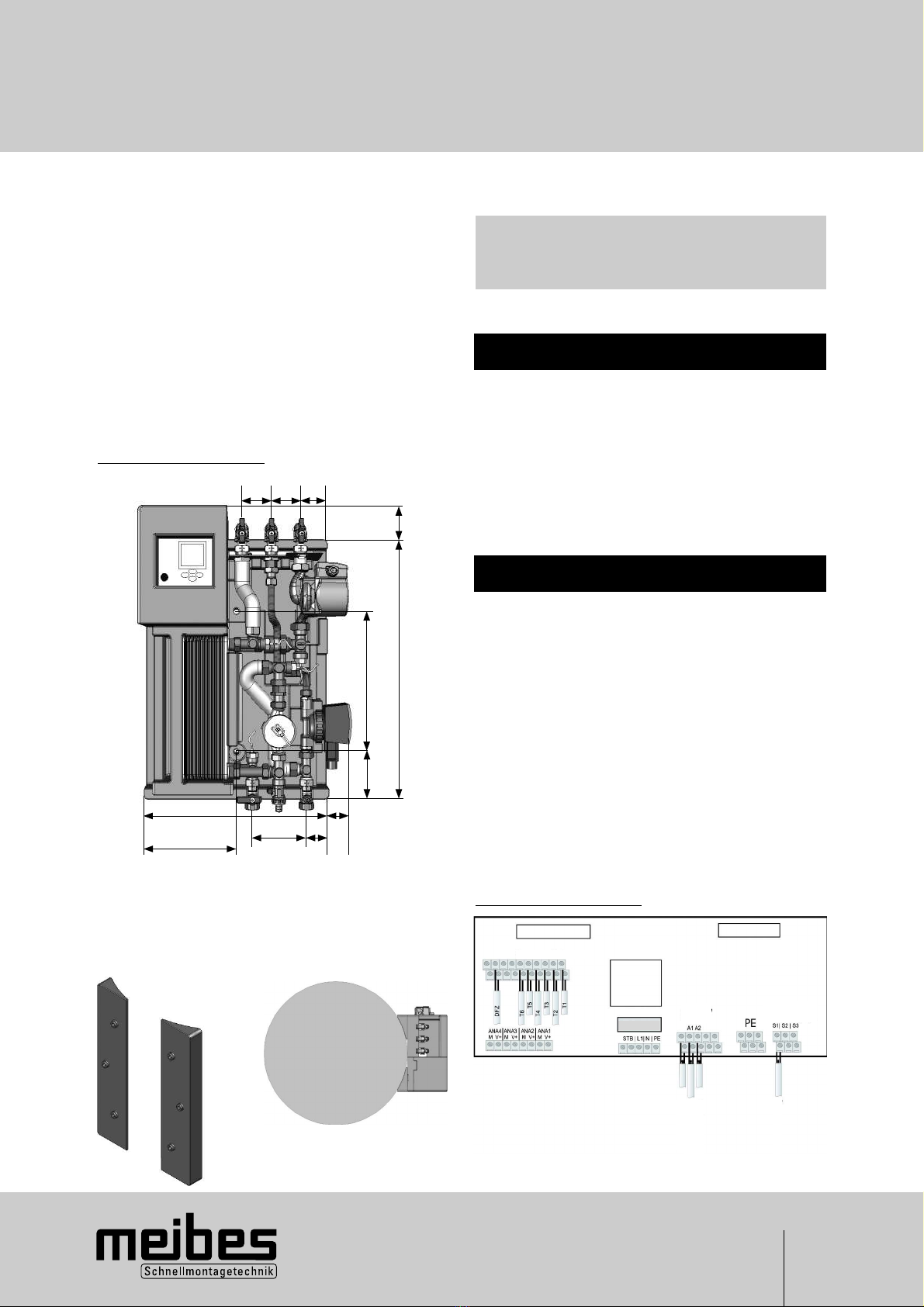
Wiring diagram
Assembly drawing
Please note:
QSafeguarding the cold water should be done
according to DIN 1988, i.e. with a safety group
and if necessary, an expansion tank.
Wall distance to the centre lines of the connections:
82mm
ADC
E
B
65 65 63
50
320
580
100
205
410
120 50
45
QThe freshwater station has been pre-assembled and
pre-wired.
QInstallation should take place on a load-bearing dry
wall.
QWith a pre-formed insulating wall it is possible to
mount the freshwater station directly onto a storage
tank (Ø 600mm) using connectable insulation
wedges (not included in delivery)
QThe freshwater station should preferably be moun-
ted low so as to be at the same height as the cold
area of the stratified storage tank!
QThe piping should be connected according to their
relevant function (see drawing).
Connectable insulation wedges
for mounting the storage tank
Example storage tank mounting
Temperature sensor
Fuse
Outputs
230V/AC
Potential-free
switch outputs
Power supply
Pump 1
Pump 2
Boiler standards
6
5. Control system
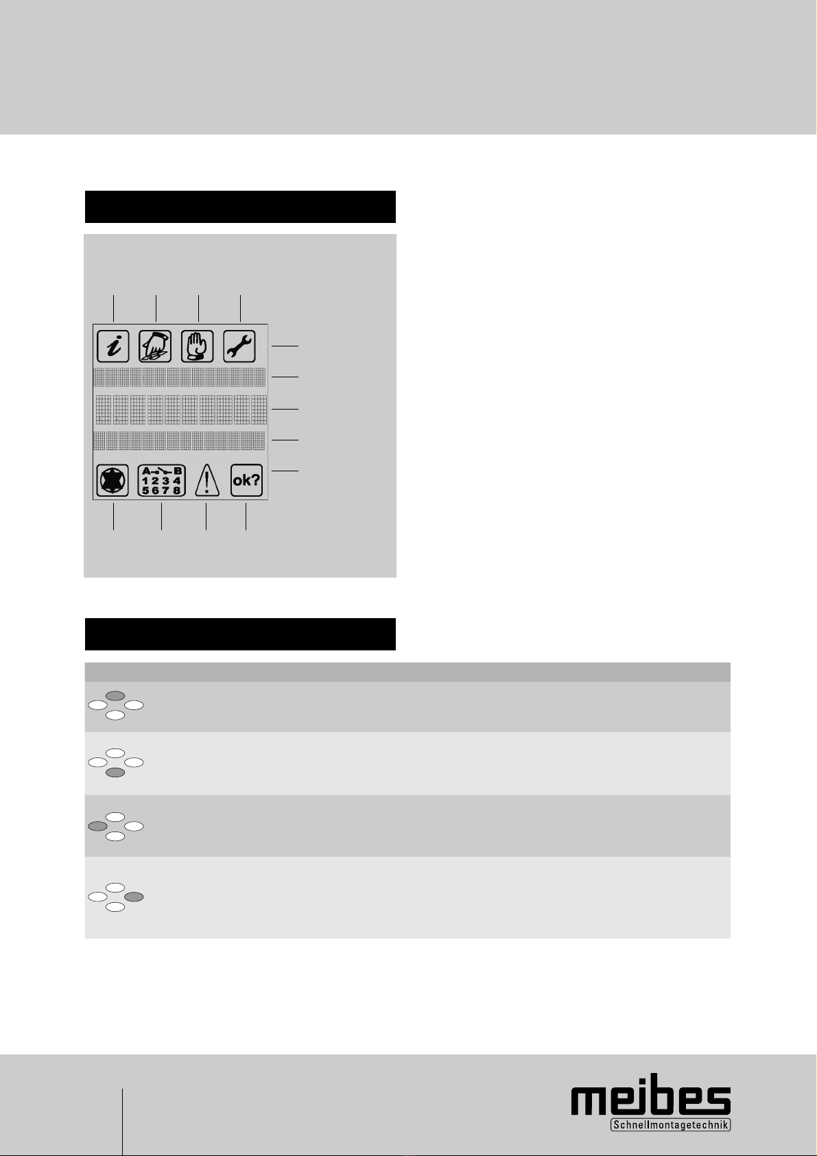
5.1 Display description
5.2 Operating keys - description
1 2 3 4
13 12 11 10
5
6
7
8
9
1 ,,Info” menu Display of all measured
values and system states
2 ,,Programming” menu Contains programming
values which can be ad-
justed by the end customer.
3 „Manual Mode“ menu Set/ reset the outputs,
determination of the
operating points
4 „Basic Setting“ menu Contains all set values,which
can only be adjusted after
„Release“.
5 Main menus
6 Measuring point assignment
7 Value/ units
8 Additional information, e.g. temperature sensor
9 Status indicator
10 „OK“ symbol Confirmation of inputs/ value
change/ value reset
11 „Important“ symbol Group error message for all
faults
12 „Outputs“ symbol Indicates which switching
outputs are active.
13 „Pump“ symbol Indicates that the controller
is active.
key Function Description
„up“
„UP“
„+“
QPage to the next menu
QValue change: incremental increase in the displayed
value, if pressed continuously the values increase continuously
„down“
„Open“
„Down“
„-“
QIn the basic menu: Open a main menu
QPage to the next menu
QValue change: incremental reduction in the displayed value,
if pressed continuously the values decrease continuously
„Page left“
„Quit“
„Cancel“
„ESC“
QPage to the left in the main menu
QQuit a menu
„Page right“
„Select“
„Confirm“
„Enter“
QQuit a menu item
QCancel a value change without saving
QPage to the right in the main menu
QSelect a menu item
QConfirm a value change with save
7
5. Control system
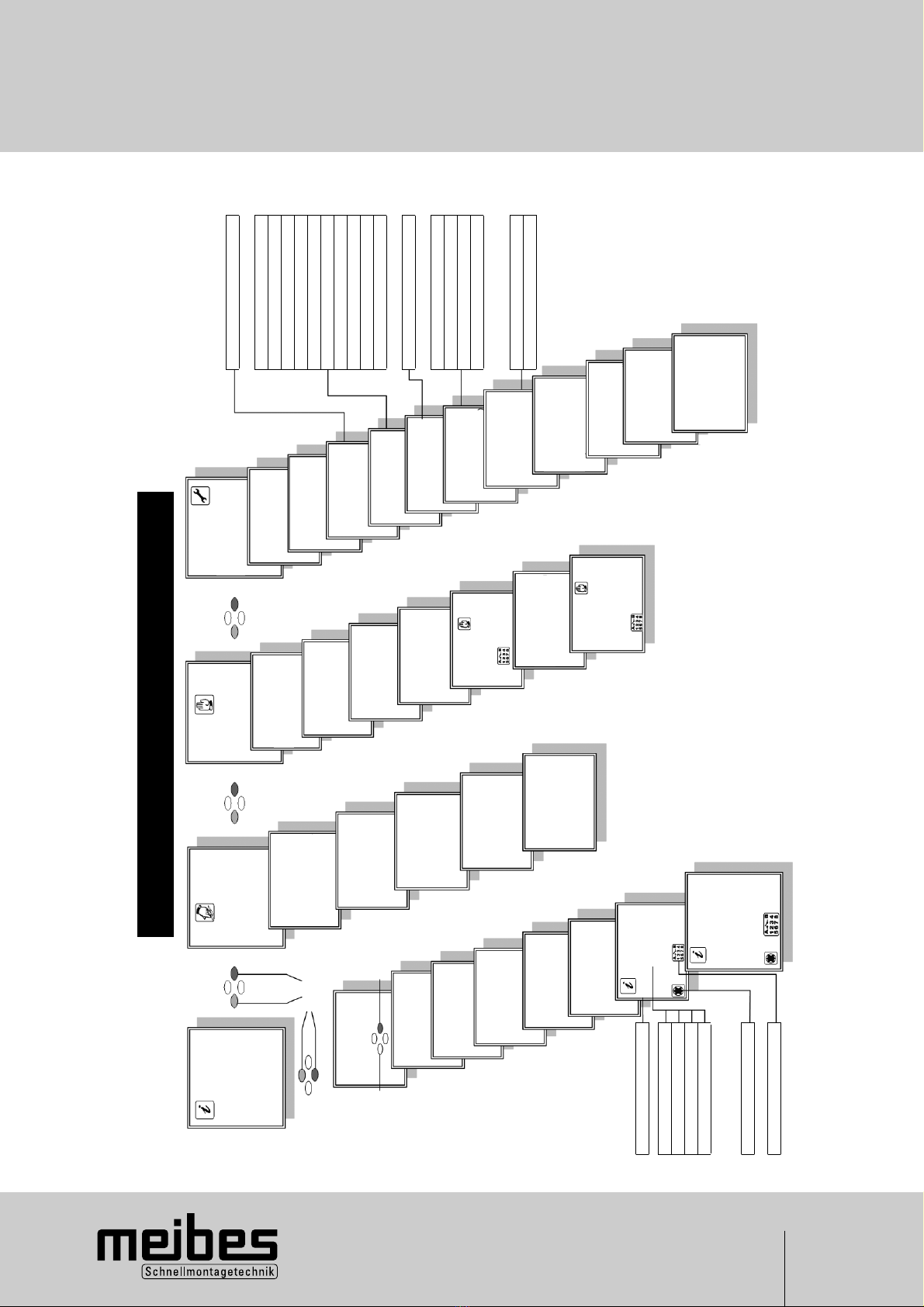
Information menu
Scrolling
Quit
Select
Confirm
Drinking water T1
Hot water VL T2
Cold water T3
Hot water RLT4
Accumulator T5
Flow l/min
6,0 l/min kW WW
P1: P2:
Status
Controlled variables
P1 % WW
Flow status VL
Tapped quantity
Off
Active 50= hot water control
Z – active = circulation
After run
Controller active
Active outputs
Programming
the menu
Heat exchanger
Hot water setpoint 50°C
WT operating mode
Cold, hot or timed
heating
WT setpoint 40°C
WT hysteresis 3K
Circulation
Time slot 1
Time slot 2
Time slot 3
Reheat 3)
65°C SP setpoint
or
15 K spread
Data logging 6)
1s to 30s
Single or cyclical
recording Control
Reset
Time
Time
Date
Manual Mode
menu
Output 1
Output 2
Output 3
Outputs
Whole test
Characteristic curve
calibration
Circulation
calibration
C: 14.0 H: 40.5
P: %
D: 5.0 T: 75.0
Basic Setting
menu
Information
Softw. version
1.XX
Pulse generator
Controller On/Off 2)
Control parameters
Characteristic
curve 1)
Heat exchanger
Circulation 1)
On/Off
Activation T5
Off/On
Reheating 1)
On/Off
Absolute or relative
Accumulator setpoint
Premixer 1)
On/Off
Factory 1)
configuration
Off/On
Release 1)
For maintenance
and settings
6)
4)
7)
7)
1) Within one minute after mains connection or executable using key combination. Access
is automatically blocked after 60 minutes!
2) Can be run with button combination: Basic Setting menu -> Release -> Select with right
click 2x -> Up, Down and Right button - press simultaneously > 2 s -> „Release On“
appears -> quit with left click.
3) Only visible if Reheat is active.
4) On visible if T5 activation in operation.
5) Only visible if a data stick is plugged in.
6) Only visible through button combination: Characteristic curve adjustment alternatively
by hand
7) Only visible through button combination
5.3 Menu structure of the V1.54 controller
Shutdown 60°C
Flow min 4 l/min
Output min 7 %
Flow middle 8 l/min
Output middle 20 %
Flow max 25 l/min
Output max 76 %
Correction per 5K 10 %
Calibration Heating medium 75°C
Calibration T cold water 15°C
Calibration Setpoint 50°C
After run 0-300 s 60s
Circ. Run time 0-600 90s
Circ. Rest time 1-120 min 0 min
Circulation setpoint 10-50°C 40°C
Sensor T3 or T6
Activation temp 35-55°C 35°C
Activation hysteresis 3-10K 3K

8
5. Control system
5.3.1 Explanation of menu items
5.3.2 Information menu
In this menu all the measured values of the temperature
sensor, volumetric flow metre as well as the control
system (system conditions) are displayed.
Status display:
Active 50 = Control system on domestic hot water
set temperature value of 50°C
Z - active 4 = Control system on circulation set
temperature value of 40°C
After-run = After-run of the circulation pump for
cooling down the stainless steel plate
heat exchanger (See 5.3.5)
Disinfection = Control system on disinfection
temperature
Off = No control system function active
5.3.3 Programming menu
The programming menu contains values which are to be
set by the end customer.
QHeat transfer unit
Hot water – set value 50°C, adjustment range
45°C to 60°C for domestic hot water. Should this
value be increased, the 60°C temperature value of
the safety shutdown should also be increased, by
going in the basic setting menu, submenu
„Controller“. A blending valve should in any event be
installed on the freshwater station outlet!
Water temperature – operating mode:
cold, hot or timed heating.
Water temperature – cold1) No heat exchange
media is added to the stainless steel plate heat
exchanger after hot water has been drawn off. It
remains at the lowest temperature level after
drawing off. This results in a favourable control
behaviour arising for the drawing off of hot water.
Water temperature – hot 1) 2) The stainless steel
plate heat exchanger is continuously kept at a
constant operating temperature. When there is a
deviation lower than the water temperature set value
minus hysteresis, the P1 is activated with a capacity
of 25 % until the water temperature set value has
been achieved. This happens provided that a tempe-
rature is measured at T2 or at the “reheating” option
at T5 which is greater than that of the hold-warm
temperature. Should this condition not be fulfilled at
T2, the temperature is again requested after a resting
period of one hour.
Water temperature – timed heating 1) 2) For the
duration of the time slot the stainless steel plate
heat exchanger is kept warm.
Water temperature – set value 2) 40°C, adjustment
range 20°C to 50°C for the hold-warm temperature
of the stainless steel plate heat exchanger for water
temperature – hot and water temperature – timed
heating.
Water temperature – Hysteresis 3 K, adjustment
range 1 K to 20 K for the water temperature set
value. Only visible if water temperature = hot or
water temperature = timed heating has been
selected!
Note:The water temperature – hot function should
be used if the buffer storage is located far from
the freshwater station and the system is
operated without circulation.
Hot water max. 5K (2 K – 10 K)
Hot water min. 5K (2 K – 10 K)
Testing period 5 min (1 min – 30 min)
An error message is displayed when the tempera-
ture exceeds or is lower than the hot water set
value. When the threshold values are exceeded or
the temperature drops below these values, a fault is
generated after the preset monitoring period, and
output S2 is switched as a potential-free contact.
The output is reset once the temperature is again
within the temperature range or it can be reset in
the information menu/error message upon actuation
of the right key. This monitoring is only valid when
drawing off takes place – not during circulation!
QTime slot
There are tree time slots available to set the
circulation. Should the switch-on and the switch-off
time be set the same, this time slot is no longer
active. For further circulation functions, see 5.3.3.
The time slots are also used for the water tempera-
ture - timed heating. (See 5.3.3)
QReheating
This menu item is only visible once the reheating
function has been activated in the basic setting
menu. If „absolute value” has been selected, „65°C
storage tank set value” will be displayed. This value
is adjustable between 20°C and 90°C. If „relative
value” is selected „15 K splay” is displayed here.
This value is adjustable between 2 K and 50 K.
For further information regarding functions, see
points 5.3.5 and 7.4. Storage tank set value = buffer
set value
QData logging
This menu is only visible if a data stick has been
connected to the front side of the control system.
Measured values can be recorded on this data stick.
In a measurement interval of 1 second (factory
setting) measured values for approx. 4.5 hours can
be logged. The data can be analysed at the plant
with special software.
QClock time
Submenu for setting the clock time, date and the day
of the week.

9
5. Control system
1) Based on the physical fact that the existing heat
energy in the heat transfer unit has to be controlled
by the control system, short-term temperature
fluctuations at the start of a hot water tapping
cannot be ruled out completely. Favourable control
behaviour is achieved with the water temperature –
cold function, which results in very short or no
reheating time!
2) The plate heat exchanger is kept hot by the heat
exchange media from the buffer. The heat exchange
media can take on temperatures of more than 60°C.
Please note that such temperatures can result in
calcium oxide precipitation!
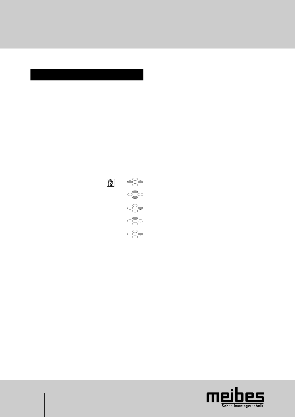
5.3.4 Manual operation menu
QThe output 1, output 2, output 3 and outputs
„overall test” can be switched on and off manually,
in order to check the functioning of the pumps.
QCharacteristic curve calibration
Here the regulation of the characteristic curve is
determined during the initial operation. (See 6.3.2)
QCirculation adjustment
In this menu item the circulation adjustment is
carried out.(See 6.3.3)
5.3.5 Basic setting menu
This menu contains important technical information and
parameters for controlling, which may be modified by
a specialist tradesman. In order to modify values, the
submenu “release” in the basic setting menu has to be
activated. (See 8)
QInformationen
Here information regarding the software and system
version is given.
QController ON/OFF 3)
Amongst other things, this menu item contains the
safety shutdown for a domestic hot water tempera-
ture of 60°C. Should this temperature be exceeded
at T1, pump P1 switches off until the temperature
drops to below 60°C. This value should be increased
when the hot water – set value is increased.
However, a blending valve should additionally be
mounted on the domestic hot water outlet of the
freshwater station. The other control parameters
should not be adjusted!
QPulse generator 2)
These values are used to adapt the flow rate
generator at the control system.
QCharacteristic curve 2)
In this menu item the pre-determined operating
points of the control system can be read.
In this menu item the pre-determined operating
points of the control system can be read. Likewise
the default value for flow max. of the characteristic
curve calibration can be modified. Should, for
example, the 25l/mm for the characteristic curve at
flow max. not be reached, the default value for flow
max. can be lowered to 15l/mm. (See 6.3.2)
QHeat transfer unit
After run 2)
Outside the circulation time and after a drawing off of
hot water, it is possible to keep the circulation pump
running afterwards. The stainless steel plate heat
exchanger is cooled down and its decalcification is
counteracted. The function of the after-run, from an
energy point of view, is only meaningful and possible
outside the circulation time!
QCirculation ON/OFF
If this function has been activated, up to three time
slots can be set in the „programming” menu.
In the time slot, controlling is always based on the
circulation temperature. If the time slot has ended, or
drawing off takes place or the circulation temperature
has been reached, the circulation switches off. It is
attached to the circulation rest time. No circulation
can be activated in the circulation rest time. To avoid
the heat transfer media in the buffer from being
mixed, the heat transfer media temperature is
checked at the heat transfer media- flow- sensor
T2 or with the option at T5 at the start of the circula-
tion process, to ensure that the heat transfer media
temperature is greater than the circulation set
temperature +2K. This happens at T2 with the
following procedure: The heat transfer pump P1 runs
for 5 minutes at minimal capacity. Should the
circulation set temperature plus 2K not be attained
after expiry of the 5 minute run time, the heat
transfer pump P1 is switched off – and restarts the
process again after a waiting period of one hour.
Following this, the flashing message „error
message flow temperature” will be seen on the
display in the information menu.
Flow increase 5 K
In some cases (high temperature drops in circula-
tion capacity), the circulation return temperature is
not reached. The set value of the circulation tempera-
ture (flow increase 5K) can be increased up to 20 K.
The input is limited to the hot water set temperature
value. Should the hot water set temperature be
reduced, the flow increase value for circulation is
also reduced!
Example:
Circulation set = 35°C, hot water set = 50°C, flow
Increase = 15 K possible
Circulation set = 40°C, hot water set = 50°C, flow
Increase = 10 K possible
Circulation set = 40°C, hot water set = 45°C, flow
Increase = 5 K possible

10
5. Control system
If a buffer sensor T5 is available as an option for the
activation of the reheating function and its temperature
is less than the circulation temperature + 2K, the
circulation is then discontinued.
As a result of the reheating function it is to be assumed
that after reheating and for a conceivable period of
time thereafter sufficient temperature is available in the
buffer.
Outside the active time slot, the circulation is always
in the “pulse generated” mode, i.e. always when a
drawing off of approx. 1 s has been carried out, the
circulation pump is switched on for the programmed
time in “circulation-running time” and the circulation is
then also blocked from being reactivated for the preset
“circulation-rest time” period.
Circulation running time = 300 s
From 0 – 600 s adjustable running time of the circulation
pump.
Circulation rest time = 5 min
From 0 – 120 min adjustable blocking time for
reactivating the circulation.
Circulation hot water set value = 40°C
From 10°C to 50°C adjustable temperature for circulation
in the time slot.
Sensor TF3 = select sensor T3 or T6 (optional)
In the factory setting T3 is used for measuring the
circulation temperature. However, an independent
sensor T6 (optional) can also be used directly in the
circulation pipes for this purpose.
Option T5: With an additional sensor T5 (optional),
which is installed in the buffer, two further functions
can be activated.
QActivation T5
If the activation T5 = on is selected, it is possible to
only put the control system into operation after a
specified buffer temperature has been attained.
Factory setting = off
Switch-on temperature = 35°C temperature
(adjustment range 35°C to 55°C)
Hysteresis = 3 K
(adjustment range 3 K to 10 K)
QReheating ON/OFF
Optionally the additional „reheating” function can be
activated. When there is a deviation lower than an
adjustable set value for the buffer, this function is an
external heat source which is activated to reheat
the buffer until it reaches the set level.
The requirement for this is that the heat source is
actually able to supply the desired temperature level.
For this purpose the contact S1 on the controller
circuit board is used. This contact can be charged
with 4 A 230 V AC. The set value for the storage
temperature can be defined as an absolute value
(fixed value e.g.: 65°C) or as a relative value.
Should the relative value be used, the set value for
the buffer temperature is calculated from the
programmed hot water – set temperature + the
entered value for the „splay”. e.g.: hot water set
temperature 50°C + splay 20 K = 70°C buffer
temperature. Should the programmed or calculated
set value deviate lower by 3 K, the external heat
source is kept activated until the set value is reached
again. The temperature values needed for this can be
set in the programming menu, under the submenu
“reheating”. (See 5.3.3)
QPre-mixer ON/OFF
As a rule, this selection is not active in this control
system!
QDisinfection
The “disinfection” function can be activated in the
basic setting menu, but only if there is a circulation
pipe available. The circulation return temperature is
controlled, which is measured at the cold water
sensor. This temperature must be attained for the
preset disinfection time period. Short-term lower
temperature deviations are corrected. In total, the
actual time that the set temperature was attained,
is counted. Should the flow temperature for the
control system not be achieved, a corresponding
error message is sent to the information menu after
30 minutes. During the disinfection of the hot water
and circulation pipes, very high temperatures are
achieved. There is therefore a danger of scalding!
Qualified personnel should take the necessary
precautions for the protection of persons and
property!
QFactory setting ON/OFF
Should the controller be set back to the original
factory positions as on delivery, this menu item is to
be activated.
QRelease
In order to „unlock“ the controller for different
settings, the following should be done:
Release by pressing the right key twice and
“OFF” will flash. Press UP and DOWN and right
key simultaneously for approx. 2s and release
changes to „ON“. To subsequently leave the setting,
press the left key.
The same operating sequence is used to block
access to the controller. Alternatively, this takes
place automatically after 60 minutes.
2) This is executable within one minute after mains
connection or by using the key combination. Access
is automatically blocked after 60 minutes.
3) Only possible to activate „release” by using the
key combination in the menu. Access is automati-
cally blocked after 60 minutes.

11
6. Initial operation and system calibration
6.1 Flushing and filling the
system
QThe entire system should be flushed before filling.
QThe flat-sealing connections of the freshwater station
should be checked for leakage and the connections
should be tightened, if necessary. When tightening
the connections, always use the appropriate tools to
counter-resist!
QAir which has accumulated in the heating system
should be removed by opening the vent screw.
Caution:
In doing so, pay attention to the system pressure and
refill, if necessary.
6.2 Controller calibration
Why is it necessary to calibrate the controller?
In doing the controller calibration and the subsequent
circulation adjustment, the values of the freshwater
station is optimised and adapted to the local conditions.
In the calibration menu you will be requested to draw
hot water three times. In doing so, the operational
points are determined for the control system and are
independently taken over into the control system.
The control system then operates on the characteristic
curve so recorded. Under optimal conditions this
process takes10 to 15 minutes. The subsequent
circulation adjustment connected to this process,
serves to log the volumetric flow of the circulation.
Note: Please draw off hot water for a longer period
before calibration so that stable temperature conditions
for cold water and hot water can be set at the fresh-
water station.
6.3 Calibration procedure
1. Pump capacity
2. Characteristic curve calibration
3. Circulation adjustment
6.3.1 Selecting pump capacity
UPS15-60 pump stage I for drawn off amounts up to
15 litres
UPS15-60 pump stage II for drawn off amounts up
40 litres
Operating at pump stage II is generally recommended
for low buffer temperatures.
6.3.2 Characteristic curve
calibration
A buffer temperature which lies above the domestic hot
water temperature is necessary for the characteristic
curve calibration. The relevant amounts are found at 2.1
Performance characteristics!
Determining the control system operating
points
1. Select the “manual” menu
2. Select the “characteristic curve calibration” submenu
3. Select using the right key; „OFF“ flashes; Use
upper key to go on “ON”; confirm with right key
twice and start a 25 litre hot water tapping accor-
ding to the menu navigation. After approx. three minutes
you will be requested to reduce the hot water discharge
volume to 8 litres. After a further approx. three minutes
you will again be requested to reduce the hot water
discharge volume (4 litres).
4. If thereafter the “characteristic curve calibration on”
is displayed again, leave this submenu using the left
key. The characteristic curve calibration is now
complete and the values are independently logged
into the control system.
5. Should it not be possible to draw off a volume of
25l/min, the value for “flow max.” can be reduced to
another value e.g. 15l/min. Additionally, a change into
the “flow max” is required in the basic setting menu,
submenu characteristic curve by using the “UP” or
“DOWN” keys, and to select using the right key. The
display 25l/min flashes and can be reduced by using
the “DOWN” key. Thereafter, confirm this setting by
pressing the right key twice.
12
6. Initial operation and system calibration
6.3.3 Circulation adjustment
A circulation adjustment is to be undertaken if the
freshwater station is fitted with a circulation pump and
a circulation pipe is connected to it! For the controller to
detect a withdrawal of water, the actual circulation cycle
must be known as the flow rate is always measured by
the sum of the hot water withdrawal and the overlaying
circulation.
Information for a software update:
As of software version V 1.54 the 3 l/min flow rate
restrictor can be left out.
A prerequisite for the calibration is that all hot water
tapping points are closed.
Procedure to be followed:
Qselect: manual menu
Qmenu item „circulation adjustment“
Qselect by using the right key,
„OFF“ flashes
Qusing the „UP“ key change to „ON“
Qconfirm twice using the right key
Qthe message “flowing” is displayed
Qwhen the message „Circulation calibration
complete“ is displayed, measuring has been
finished.The measured value is displayed
and independently logged into the control
system.
QLeave the menu using the left key
13
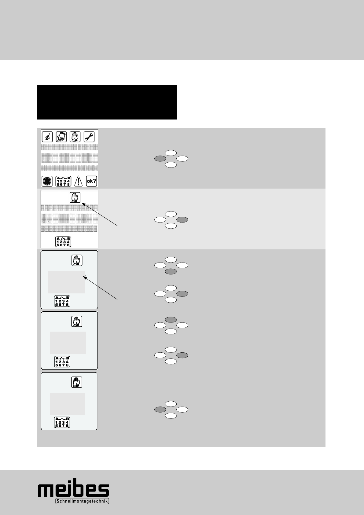
6. Initial operation and system calibration
6.3.4 Detailed description of
characteristic curve
calibration
Determining the operating points of the
control system
QManual operation menu
QCharacteristic curve calibration submenu
1x Leave the info menu using the “escape” key
2x
flashes
Select the menu: manual operation
5x
and then
1x
flashes
Select the menu: manual operation
Qselect using right key, OFF flashes.
1x
2x
QUsing the upper key, switch to On and
Qconfirm twice with the right key.
Calibration procedure starts.
1x
Kindly follow the menu guidance on the
display.
Consecutive drawn amounts of 25 litres,
8 litres and 4 litres are required. After the
relevant operating points of the pump have
been determined and independently logged
into the control system, characteristic curve
calibration “on” again appears on the display.
Leave this submenu using the left key.
The characteristic curve calibration is now
complete.
Characteristic
curve off
calibrate
Characteristic
curve on
calibrate
Withdrawal
starts

14
7. System examples
7.1 Freshwater station with
circulation in a time-slot
and with tapping detection
outside the time slot
QInitial operation and system calibration from point 6
QSetting the time and date, point 5.3.3
QDomestic hot Qset value e.g.: 50°C, point
water 5.3.3 and 5.3.5
QCirculation QBasic setting menu,
Circulation submenu = select
“on”, point 5.3.5
Q In programming menu,
circulation submenu up
to 3 select time slot,
point 5.3.3
Q Circulation temperature 40°C,
for control in time slot,
point 5.3.5
Q Circulation time e.g.: 60 s,
Circulation rest time.: e.g.
10 min, for controlling the
circulation through tapping
detection outside the
time slot, point 5.3.5
QHeat transfer unit QWT = cold, point 5.3.3
QTime lag Qe.g.: 20 s, point 5.3.5
7.2 Freshwater station with
circulation only via tapping
detection
QInitial operation and system calibration from point 6
QSetting the time and date, point 5.3.3
QDomestic hot Qset value e.g.: 50°C,
water point 5.3.3 and 5.3.5
QCirculation QBasic setting menu,
Circulation submenu = select
“on”, point 5.3.5
Q In programming menu,
Circulation submenu is the
start and stop times within
each 3 time slots which are
to be set at the same time
e.g.: start 6h00 - stop 6h00
point 5.3.3
Q Circulation time e.g.: 60 s,
Circulation rest time e.g.:
10 min, point 5.3.5
QHeat transfer unit QWT = cold, point 5.3.3
QTime lag Qe.g.: 20 s, point 5.3.5
7.3 Freshwater station without
circulation
QInitial operation and system calibration from point 6
QSetting the time and date, point 5.3.3
QDomestic hot Qset value e.g.: 50°C, point
water 5.3.3 and 5.3.5
QCirculation QBasic setting menu,
Circulation submenu = select
“off”, point 5.3.5
QHeat transfer unit QWT = cold can be selected,
if the distance between
the buffer and the freshwater
station is not too great.
After-run e.g.: 20 s,
point 5.3.5
Q WT = hot can be selected,
if there is a great distance
between the buffer and the
freshwater station, and the
comfort of the “rapid” hot
water drawing has been
attained. Set the after-run
point 5.3.5 on nought, as no
circulation pipe is available.

15
7. System examples
7.4 Freshwater station with
reheating option and/or
activation
The freshwater station with or without circulation can be
extended by two functions via an additional temperature
sensor T5 (not included in delivery) in the buffer. These
functions must be activated in the basic setting menu.
Point 5.3.5
The temperature sensor T5 becomes visible in the
information menu after activation.
1. A boiler must be requested to reheat the buffer.
For this a potential-free contact S1 on the control
circuit board is used.
This contact can be charged with 4 A 230 V AC.
A description as well as the settings for the reheating
option is found under point 5.3.5, reheating menu
item.
2. The same temperature sensor T5 can be used to
specify the buffer temperature, from where the hot
water regulation and the circulation are activated.
This function makes sense if the buffer temperature
could at some point take on unfavourably low values
as a result of renewable energy sources, and if the
freshwater station should not yet run at such low
buffer temperatures.
A description as well as the settings for the option
activation can be found under point 5.3.5, Activation
menu item.
7.5 Increasing the domestic
water set value
The following example is used to show what factors
should be taken into account when the domestic hot
water temperature is to be increased from 50°C to 60°C:
1. WW – set value increase
2. Increase the electronic safety shutdown and install a
blending valve.
3. Carry out a characteristic curve calibration!
re 1. In the programming menu, submenu heat transfer,
increase the hot water set value from 50°C to
60°C. To do this, select 50°C with the right key.
Once 50°C flashes, the value can be increased
to 60°C by using the upper key. Thereafter, confirm
by pressing the right key twice.
re 2. Release the operating level for the specialist
tradesmen in the basic setting menu. See point 7.
In the programming menu, submenu controller,
increase the menu item 60°C deactivation from
60°C to 70°C. To do this, the submenu controller
must be selected by pressing the right key once
until the bracket goes out. Then press the lower
key once. 60°C activate will be displayed. Now
select by pressing the right key once until the
60°C flashes. Using the upper key, increase to
70°C and confirm by pressing the right key twice.
You have now increased the safety shutdown
(scalding protection) of the control system to a
higher value and must now re-install a blending
valve on the hot water outlet!
re 3. Characteristic curve calibration see point 6.2 to
6.3.2
16
7. System examples
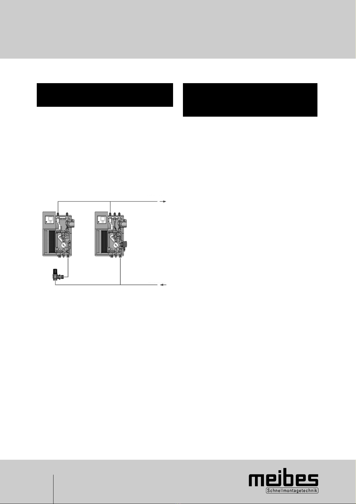
7.6 Freshwater station as
cascade connection
Should larger volumes of hot water be needed, overflow
valves allow for the interconnection of two or more
freshwater stations as a cascade. Here, the service
water circulation module can be left out for the second
and other freshwater stations.
The circulation is controlled only by the first freshwater
station.
Basic circuit diagram:
Second station First station
7.6.1 Initial operation and
system calibration of the
freshwater cascade
First station
QInitial operation and system calibration from point 6
QSetting the time and date, point 5.3.3
QDomestic hot Qset value e.g.: 50°C, point
water 5.3.3 and 5.3.5
QCirculation QBasic setting menu,
Circulation submenu = select
“on”, point 5.3.5
QIn programming menu,
circulation submenu up to
3 select time slot, point 5.3.3
QCirculation temperature
40°C, for control in time slot,
point 5.3.5
QCirculation time e.g.: 60 s,
Circulation rest time.: e.g.
10 min, for controlling the
circulation through tapping
detection outside the time
slot, point 5.3.5
QHeat transfer unit QWT = cold, point 5.3.3
QTime lag Qe.g.: 20 s, point 5.3.5
Second station
QInitial operation and system calibration:
The determined values of the characteristic curve
calibration of the first station are taken over. These
values are read in the first control system in the
basic setting menu, characteristic curve submenu
and in the same menu they are set in the second
control system.
QSetting the time and date, point 5.3.3
QDomestic hot QSet value e.g.: 50°C,
water point 5.3.3 and 5.3.5
QCirculation off
QHeat transfer unit QWT = cold, point 5.3.3
QAfter-run Qe.g.: 20 s, point 5.3.5
Differential pressure-overflow valve
Hot water should be drawn off of e.g.: 35l/min.
This domestic water volumetric flow can be read in
the control system information menu of the first
freshwater station. Set the differential pressure-
overflow valve so that the second freshwater station
starts operating (determination of opening pressure of
the overflow valve). Loosen the locking screw at the
differential pressure-overflow valve. Afterwards the
opening pressure can be adjusted in stages by turning
the hand wheel valve. The selected position should
subsequently be checked at the locking screw to
ensure it against accidental adjustment.
Required accessories:
Overflow valve DN 25 for
Cascade connection
Adjustment range:
100 to 500 mbar
Article no.: 69072.9
Domestic water
Domestic water
hot
cold

17
8. Releasing operating level for specialist
tradesmen!
QIn the basic setting menu press the „down“ key
downwards nine times until submenu release is
attained [values].
QNow press „right” key twice, this causes “off” to
flash.
QPress the „up“ and „down“ and „right“ keys
simultaneously for approx. 2 s, release switches
to “on”.
QThereafter leave the menu by using the “left” key.
7.7 Disinfecting the hot water
and circulation pipes
During the disinfection of the hot water and circulation
pipes, very high temperatures are generated.
There is a danger of scalding!
Qualified personnel should take the necessary
precautions for the protection of persons and property!
7. System examples
Example for setting the control system:
1. Release the operating level for the specialist
tradesmen in the basic setting menu.
2. In the basic setting menu, submenu
disinfection, select “in”.
3. Set the hot water set value.
Adjustment range 65 - 75°C
4. Select disinfection time (duration of
disinfection) Adjustment range 0 - 60 minutes
5. Select the day, week day or daily.
6. Start time (0 - 24 hours)
This function should be deactivated after
disinfection! The function is described in
5.3.5!
The releasing of the operating level can be reset again in the same way.
Access to the adjustable values is blocked automatically after 60 minutes!

18
9.Trouble-shooting
The following is to be checked if the domestic hot water
temperature is not reached:
QSystem voltage (fuses)
QBuffer temperature
QVent the freshwater station
QA temperature sensor interruption or a short circuit
is displayed in the information menu by a flashing
general error message and is shown individually
when requesting each sensor.
QCarry out characteristic curve calibration, from
point 6.3.2.
QCarry out a circulation adjustment, point 6.3.3.
QDuring a hot water withdrawal, the circulation pipe
becomes cold.
Cause: The return flow preventer in the connecting
nipple above the circulation pump can start leaking
due to soiling in the cold water network.
QFlow rate metre: To check this, a hot water tapping
is required and the flow in litres per minute read in
the information menu. An intact flow rate metre
should show a relatively constant value. Should
fluctuations occur, check whether this comes from
the domestic water network, for example in pressure
increase systems
QSet the freshwater station according to the system
examples.
QThe pumps P1 and P2 run alternatively and the status
display in the information menu switches between
active 50, after-run and off.
Q Carry out a circulation adjustment, point 6.3.3.
QAfter several months of smooth running operation
the hot water capacity is no longer reached.
Q If a dirt filter has been installed in front of the
station, this should be cleaned.
Q Check return flow preventer.
Q Vent the buffer and the freshwater station
QA short time after drawing off hot water at the tap
(e.g.: washbasin) the hot water temperature drops
sharply even though the control system displays
e.g.: 50°C hot water temperature.
Q The return flow preventer should be checked in
the connecting nipple above the circulation pump
to see if it leaks as a result of soiling in the cold
water system and if cold water has been
pressed into the circulation piping.
Q The circulation does not work:
Q Carry out circulation adjustment!
Q Check time slot!
Q The temperature of the heat transfer media
in the buffer is too low.
The circulation set temperature + 2 K is not
being reached at T2 or at T5, if present.
(see point 5.3.5 Circulation)
Please ensure that there is a sufficient quantity
of heat in the buffer!
With option T5 „reheat buffer“, a type of boiler
can be activated.

19
10. Factory setting and personal setting
Menu Submenu Factor
setting
Personal
setting
Heat transfer unit
Hot water set value 50°C
Water temperature (WT)
operating mode hot / cold / timed
heating
cold
Hot water set value 40°C
Water temperature hysteresis 3 K
Hot water max 5 K
Hot water min -5 K
Test time 5 min
Circulation
Time slot 1
Time slot 2
Time slot 3
6:00 - 9:00
11:00 - 13:00
16:00 - 20:00
Circulation
adjustment
Volumetric flow rate
Circulation 3 l
Pulse generator 72 lmp. / litre
Characteristic curve
Flow min 4 l/min
Capacity min 8 %
Flow middle 8 l/min
Capacity middle 20 %
Flow max 25 l/min
Capacity max 76 %
Correction 5 K 10 %
Heat transfer media adjustment 75°C
Temperature - cold water adjustment 15°C
Se value adjustment 50°C
Heat transfer unit After - run 20 s
Circulation
On/Off on
Running time 90 s
Rest time 0 min
Set value 40°C
Flow increase circulation 5 K
Temperature sensor 3 or 6 TF3
Activation T5
On or Off Off
Temperature 35°C
Hysteresis 3 K
Reheating On/Off Off
absolute or relative absolute
Pre-mixer On/Off Off
Disinfection On/Off Off
Hot water set value Off
Disinfection time 70°C
Start Monday
Start 1:00
UPS 15-60 Pump stage 2
Table of contents
Popular Industrial Equipment manuals by other brands


SUHNER MACHINING
SUHNER MACHINING MAX40R Technical document

Schmalz
Schmalz FS Series Assembly instructions

Siemens
Siemens SIRIUS 3RU1.1 Reference manual

Huawei
Huawei FusionModule 1000A40 Maintenance Guide

KINSHOFER
KINSHOFER EuroRail Operator's guide

Des Champs Technologies
Des Champs Technologies HVAC Air-Trap P Series Installation, operation and maintenance manual