Senis MMS-1A-RS User manual

Operation Manual
MMS-1A-RS / MMS-1X-RS
Revision 4.0, September, 2020
Doc Nr: MP.MMS-1A-RS.OM.400.02_E
Page 1/74
Operation Manual
Senis AG
Neuhofstrasse 5a
CH-6340 Baar
Phone: +41 (44) 508 7029
Web : www.senis.ch
Email: [email protected]

Operation Manual
MMS-1A-RS / MMS-1X-RS
Revision 4.0, September, 2020
Doc Nr: MP.MMS-1A-RS.OM.400.02_E
Page 2/74
1. Contents
2. Table of Revisions .......................................................................................................................... 4
3. Safety Precautions......................................................................................................................... 5
4. Information.................................................................................................................................... 7
5. Preparation for use........................................................................................................................ 8
UNPACKING AND DRIVE UNBLOCKING ........................................................................................................................8
Unpacking Procedure.....................................................................................................................................8
Unblocking Procedure..................................................................................................................................12
INSTALLATION AND SETUP......................................................................................................................................... 14
Standard Package Content .......................................................................................................................... 14
Connecting the System................................................................................................................................. 16
Connecting Instruction................................................................................................................................. 17
System Setup................................................................................................................................................18
Mapper Software Installation ...................................................................................................................... 19
OPERATIONAL CONDITIONS.......................................................................................................................................19
6. General description ..................................................................................................................... 20
OVERVIEW..................................................................................................................................................................20
SENIS high-resolution magnetic-field-to-voltage transducer (in short: magnetic transducer) ....................20
Cartesian Moving Platform (CMP) ...............................................................................................................22
Data acquisition and signal processing........................................................................................................24
Motion Control............................................................................................................................................. 24
MH8 Rotation Probe Head (only MMS-1X-RS).............................................................................................24
FOLDERS AND FILES.................................................................................................................................................... 26
CONNECTION DIAGRAMS...........................................................................................................................................30
FUNCTIONAL VERIFICATION.......................................................................................................................................31
7. Operation instructions................................................................................................................. 35
DASHBOARD TAB .......................................................................................................................................................35
Top level controls (always visible)................................................................................................................ 35
MANUAL CONTROL TAB.............................................................................................................................................36
System navigation........................................................................................................................................36
Manual positioning options .........................................................................................................................37
Absolute and relative movement................................................................................................................. 37
Data collection ............................................................................................................................................. 37
Field Graphs ................................................................................................................................................. 37
KEYBOARD CONTROLS ...............................................................................................................................................38
CALIBRATION TAB ......................................................................................................................................................38
Coordinate system and starting points: .......................................................................................................39
Center of rotary stage calibration................................................................................................................39
FSV calibration .............................................................................................................................................41
Defectoscope calibration ............................................................................................................................. 43
Rotation alignment ...................................................................................................................................... 43
Touch alignment .......................................................................................................................................... 43
Cube Calibration...........................................................................................................................................44
Sliding probe calibrations (Option MMS-SLIDE)...........................................................................................46
SETUP TAB..................................................................................................................................................................48
Measurement Profiles..................................................................................................................................48
Measurement modes (Legacy).....................................................................................................................49
Command Editor (List of Commands) ..........................................................................................................50
Rotary scan path examples..........................................................................................................................50
Linear scan path examples........................................................................................................................... 51
Report types.................................................................................................................................................52
Multilayer Scan (Slices) ................................................................................................................................ 52
Scanning Resolution..................................................................................................................................... 53

Operation Manual
MMS-1A-RS / MMS-1X-RS
Revision 4.0, September, 2020
Doc Nr: MP.MMS-1A-RS.OM.400.02_E
Page 3/74
MEASUREMENT TAB ..................................................................................................................................................53
Single slice visualization............................................................................................................................... 54
Polar plot visualization.................................................................................................................................54
Multi slice visualization................................................................................................................................ 55
Basic analysis ............................................................................................................................................... 55
Multipole analysis ........................................................................................................................................56
Diameter Analysis ........................................................................................................................................ 58
2D graph visualization .................................................................................................................................59
3D graph visualization .................................................................................................................................59
ADDITIONAL ANALYSIS SOFTWARE (OPTION MMS-ANALYSIS).................................................................................. 60
DIMENSIONAL TAB (OPTION MMS-CMM) .................................................................................................................63
ADMINISTRATION TAB ...............................................................................................................................................66
System Setup................................................................................................................................................66
Reporting Setup ...........................................................................................................................................66
Movement Setup.......................................................................................................................................... 66
8. Options ........................................................................................................................................ 67
DEFECTOSCOPE (OPTION MMS-DEF) ......................................................................................................................... 67
ANISOTROPIC MAGNETO RESISTANT (AMR) PROBE (OPTION MMS-AMR) ...............................................................68
CLEAN ROOM COMPATIBILITY (OPTION MMS-CR) .................................................................................................... 70
9. Troubleshooting........................................................................................................................... 71
MAPPER CANNOT BE TURNED ON .............................................................................................................................71
MAPPER HITS THE LIMIT SWITCH DURING OPERATION (GO TO ZERO, GO TO START POSITION, …).........................71
TOUCH SENSOR IS TAKING TOO LONG TO OPEN ....................................................................................................... 71
FSV CALIBRATIONS FAILS............................................................................................................................................ 71
NO MAGNETIC FIELD VALUES ARE DISPLAYED...........................................................................................................71
MAGNETIC FIELD VALUES ARE WRONG ..................................................................................................................... 71
HIGH MEASUREMENT NOISE .....................................................................................................................................72
AXIS DOES NOT MOVE/MOVEMENT IS INTERRUPTED...............................................................................................72
TECHNICAL SUPPORT .................................................................................................................................................72
10. Maintenance................................................................................................................................ 73
MAINTENANCE INTERVALS ........................................................................................................................................73
BALL SCREW LUBRICATION ........................................................................................................................................73
BALL SCREW GREASING .............................................................................................................................................73
LINEAR ENCODER GLASS SCALE CLEANING................................................................................................................ 73
11. Additional resources.................................................................................................................... 74

Operation Manual
MMS-1A-RS / MMS-1X-RS
Revision 4.0, September, 2020
Doc Nr: MP.MMS-1A-RS.OM.400.02_E
Page 4/74
2. Table of Revisions
Date
Manual release
Software version
Description
09/2020
4.0
3.0
New template
New: full screen interface description
Removed: Mapper software design, project specific
information, Detailed software installation
instructions, technical data, Key features and
applications
Replaced: Maintenance instructions with reference
to producer documents where possible
Added: Troubleshooting, Additional resources

Operation Manual
MMS-1A-RS / MMS-1X-RS
Revision 4.0, September, 2020
Doc Nr: MP.MMS-1A-RS.OM.400.02_E
Page 5/74
3. Safety Precautions
Read the manual before operating the mapper.
Do not connect the device to any power source other than the one delivered by
manufacturer and specified in this document.
Do not use any cables other than the ones delivered by manufacturer and specified in this
document.
Do not touch the system or magnet under the test during the measurement.
If you discover any abnormalities while checking the device, before operation or during
operation, stop using the device immediately and inform manufacturer.
Do not disassemble or modify the device. Only manufacturer approved technicians are
allowed to repair, disassembly and perform device modifications.
Remove the power plug prior to carrying out device maintenance and/or device checks.
Do not expose the device, especially Hall probe and optical encoders mounted on linear
modules to the direct sunlight or to strong light sources.
Do not subject the device to impacts.
Keep the top of the device and interior of the protective cabinet (if delivered) clear of all
foreign objects. only magnets under the test are allowed inside the cabinet.
Use device in a place where it can be maintained in the horizontal position.
When moving the device, first lift it and then carry it. Do not move the device by pulling the
cables.

Operation Manual
MMS-1A-RS / MMS-1X-RS
Revision 4.0, September, 2020
Doc Nr: MP.MMS-1A-RS.OM.400.02_E
Page 6/74
When removing the plug, hold and pull the plug itself. do not remove it by pulling the cable.
Do not apply undue force to plugs, cables or the sensor.
Do not unplug any cables while measurement is in progress. always stop the software
program prior to unplugging the cables.
Do not use abrasive means for cleaning the scanning surface.
The PC cards must not be removed or the hardware drivers uninstalled. Always consult
manufacturer before attempting to install devices.
Do not put objects of more than 20kg weight onto the mapper table unless it was declared
for higher weights.
Do not put objects of more than 7kg weight onto the rotary stage of the mapper table unless
the special rotary stage was integrated for heavy objects.
Do not change the measurement probe while electronic box is turned on.
If the border switches on the linear modules were hit, the electronic box will turn off and the
probe movement will stop. To continue working, manually move probe in opposite direction
to the one when probe was hit the boarder switch (in order to neutralize following software
error) and turn on the electronic box.
When mapper is in operation (scanning or calibration), do not activate (press) movement
commands on the keyboard.

Operation Manual
MMS-1A-RS / MMS-1X-RS
Revision 4.0, September, 2020
Doc Nr: MP.MMS-1A-RS.OM.400.02_E
Page 7/74
4. Information
Magnetic Field Mapper MMS-1A-RS / MMS-1X-RS is the high-end version of the SENIS Magnetic Field
Mapping Systems. It allows users to perform a fast, high resolution mapping of magnetic flux density around
permanent magnets, electromagnets or electronic circuit boards. The map of the magnetic field can be
presented as color coded 2D or 3D visual displays on a PC screen and as a table of numerical measured values.
Measured data are analyzed in real-time, which provide data analysis capabilities for an advanced inspection,
characterization and quality control of permanent magnets.
Due to unique features of the applied fully integrated 3-axis Hall probe, all three components of the magnetic
field (Bx, By, Bz) are measured simultaneously at virtually same point. The magnetic field sensitive area of the
applied Hall probes is within a 150 µm x 150 µm square, which allows measurements of the homogeneous
and highly inhomogeneous magnetic fields. The mapping system is controlled by an extremely easy-to-use-
software, built on MS Windows platform and LabVIEW. Magnet scanning profiles are fully customizable.
Figure 1: Magnetic Field Mapping System –MMS-1A-RS (standard size) and MMS-1X-RS (large-size mapper)

Operation Manual
MMS-1A-RS / MMS-1X-RS
Revision 4.0, September, 2020
Doc Nr: MP.MMS-1A-RS.OM.400.02_E
Page 8/74
5. Preparation for use
Unpacking and drive unblocking
Unpacking Procedure
For protective Cabinet installation, refer to the document Installation of the Protective
Cabinet for the Mapping System.pdf
The Hall Probe is very fragile. Take extra care when unpacking it and handling it manually.
It is highly recommended that the system unpacking and operation setup procedure is performed by a
certified SENIS engineer or by an authorised SENIS partner. If this is not the case, SENIS cannot be held
responsible for any system malfunction or damage.
The process of unpacking the Mapper is described on the following figures. Please take care when moving the
device in order not to damage the cables, switches or other Mapper parts.
Figure 2: The Mapper is delivered in a suitable wooden box

Operation Manual
MMS-1A-RS / MMS-1X-RS
Revision 4.0, September, 2020
Doc Nr: MP.MMS-1A-RS.OM.400.02_E
Page 9/74
Figure 3: Unscrew the top cover of the box
Figure 4: Remove the cover
Figure 5: Mapper System packed in the wooden box
Figure 6: Unscrew the front side of the box

Operation Manual
MMS-1A-RS / MMS-1X-RS
Revision 4.0, September, 2020
Doc Nr: MP.MMS-1A-RS.OM.400.02_E
Page 10/74
Figure 7: Remove the front side of the box
Figure 8: Mapper is fixed on the mapper holder board
Figure 9: Unscrew the Mapper holder board from the top and pull-out the bord with the Mapper

Operation Manual
MMS-1A-RS / MMS-1X-RS
Revision 4.0, September, 2020
Doc Nr: MP.MMS-1A-RS.OM.400.02_E
Page 11/74
Figure 10: Turn the mapper and lay it on the side. Unscrew the M10 screws.
Figure 11: Screw-in the adjustable feets, which are delivered with the machine
Figure 12: Place the Mapper on the firm and stable table

Operation Manual
MMS-1A-RS / MMS-1X-RS
Revision 4.0, September, 2020
Doc Nr: MP.MMS-1A-RS.OM.400.02_E
Page 12/74
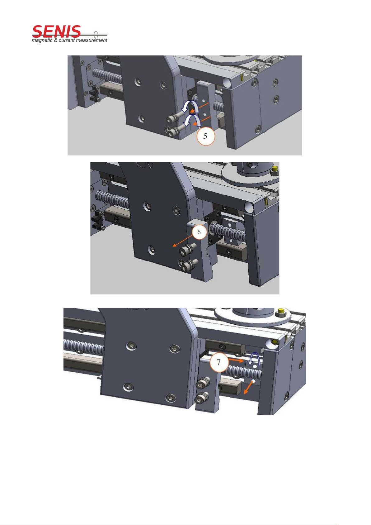
Unblocking Procedure
The unblocking procedure is described in the following figures. Blockers have to be carefully removed from all
three linear modules (X, Y and Z axes). Please pay attention during the unblocking in order not to damage the
border switches.
Figure 13: Blocker and Border Switch on the Y-axis
Figure 14: Linear module in blocked state
Figure 15: Position of blockers
Operation Manual
MMS-1A-RS / MMS-1X-RS
Revision 4.0, September, 2020
Doc Nr: MP.MMS-1A-RS.OM.400.02_E
Page 13/74
Figure 16: Unscrew the hexagonal screws
Figure 17: Pull out the blocker
Figure 18: Rotate and remove the screwing part

Operation Manual
MMS-1A-RS / MMS-1X-RS
Revision 4.0, September, 2020
Doc Nr: MP.MMS-1A-RS.OM.400.02_E
Page 14/74
Installation and Setup
Standard Package Content
•Mechanical Probe Positioning System includes: Cartesian Moving Platform, Touch Sensor with Probe
Holder and Hall Probe, Rotation Stage, Zero Gauss Chamber, Magnet Holder and FSV Calibration Tool.
a)
b)
c)
d)
Figure 19: Mechanical Probe Positioning System or Cartesian Moving Platform
a) Standard-size Mapper with scanning volume (135x135x135) mm
b) Large-size mapper with the scanning volume (500x500x300) mm
c) Standard-size mapper in the protective box
d) Large-size mapper in the protective box

Operation Manual
MMS-1A-RS / MMS-1X-RS
Revision 4.0, September, 2020
Doc Nr: MP.MMS-1A-RS.OM.400.02_E
Page 15/74
•Electronic Box (WxDxH: (32x45x14)cm / 5kg), including the power cord
Figure 20: Electronic Box (configuration of the electronic box may differ)
•Desktop Computer (WxDxH: (15 x 47 x 37) cm / 5 kg) with a Windows 7/10 operating system and
mapper software installation on it (CD is included), USB cable, keyboard, mouse and display.
The keyboard language shall remain English since other languages might introduce issues
(e.g. decimal point issue).
•Cables for connecting the Cartesian Moving Plaform, Electronic Box and Computer
Figure 21: Connecting Cables
•Emergency Stop Taster
Figure 22: Emergency Stop Switch
•Documentation: Operation Manual, Command Syntax, Calibration Certificates, Testing reports
Operation Manual
MMS-1A-RS / MMS-1X-RS
Revision 4.0, September, 2020
Doc Nr: MP.MMS-1A-RS.OM.400.02_E
Page 16/74
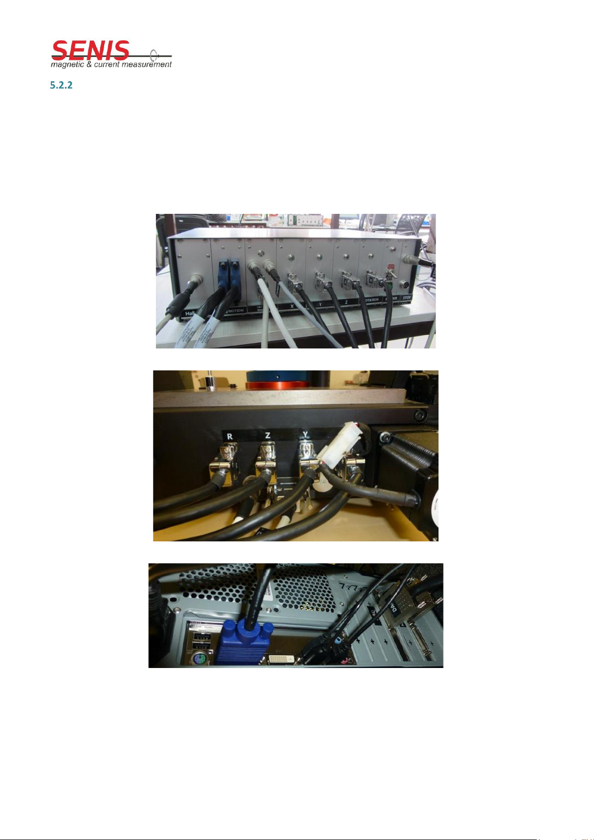
Connecting the System
Since most of the modules are already connected inside the Electronic Box (control units, motor drivers,
power supply, motherboard), only a few connections are required to make the system fully operational. A
proper way to connect the Electronic Box to the Cartesian Moving System and to the PC is shown in the
Figures below (connector positions on the Electronic Box may differ depending on the system configuration).
All cables/connectors and corresponding slots are marked, so that the connecting procedure is user friendly
and straight forward.
Figure 23: Electronic Box Connectors
Figure 24: –Connectors on the back side of the cartesian moving platform
Figure 25: Computer Connectors, including NI DAQ and NI Motion Control cards

Operation Manual
MMS-1A-RS / MMS-1X-RS
Revision 4.0, September, 2020
Doc Nr: MP.MMS-1A-RS.OM.400.02_E
Page 17/74
Connecting Instruction
•Connect the Hall probe, the touch sensor, step motors, FSV tool supply, encoders, X/Y/Z linear
modules and the rotating stage (from the Cartesian Moving Platform) to the electronic box.
•Connect the Emergency Stop Switch to the Electronic Box.
•Connect the NI Motion Control and the NI DAQ (Data Acquisition Card) from Electronic Box to PC.
•Connect the keyboard, the mouse and the monitor to the PC. The PC and the monitor have its own
power supply.
•On the rear side of the Electronic Box there is the IEC connector along with the electronic fuse (250
V(a.c.) / 110 V (a.c.), (20x5 )mm). Plug-in the power cord into the IEC socket on the back panel of the
Electronic Box and then into the wall socket.
All inputs/outputs are labelled (label plates) on the Electronic Box, on the PC and on the
back panel of the Mapper.
In case a Magnetic Field Mapper is labelled by a CE mark, it has its validity only if the
Protective Cabinet is mounted. CE can be provided also in the case that customer guaranties
the mechanical protection (operator cannot touch linear modules during the operation).
The keyboard language shall remain English since other keyboards might introduce issues
(e.g. decimal point issue).

Operation Manual
MMS-1A-RS / MMS-1X-RS
Revision 4.0, September, 2020
Doc Nr: MP.MMS-1A-RS.OM.400.02_E
Page 18/74
System Setup
It is highly recommended that the system setup is performed by a certified SENIS engineer
or by an authorised SENIS partner. If this is not the case, SENIS will not be held responsible
for any system malfunction or damage. The set files (configuration and calibration) on the
installation disk will not match your system if the system was disassembled after shipping.
Each time a system component is physically moved or replaced; set files must be changed!
After the system is unpacked and fixed on the stable table, all system components should be visually
inspected. A special attention has to be paid to the boundary switches located on both sides of each linear
module (X, Y, Z) of the mechanical probe positioning system.
After the system is successfully inspected, it is ready for startup procedure:
•Turn on the computer.
•Do not start the Mapper software program before turning on the Electronic Box. Prior to turning on
the Electronic Box, make sure the Emergency Stop Switch is not closed (otherwise the Electronic Box
cannot be turned on).
•Make sure the Emergency Stop Switch is released.
•Turn on the Electronic Box by setting the on/off switch on the front panel of the Electronic Box to
“on”. Note, this doesn’t turn on the Electronic Box yet and no LED indicators are turned on. After the
switch is in “on” position, press the green button to turn the system on. This procedure is required in
order to protect the system from an unattended startup (e.g. after a power blackout). Once the
system is on, one red LED and five green LEDs on the front panel of the electronic box will be on.
•ONLY FOR THE VERSION OF THE MAPPER WITH THE CE SIGN (PROTECTIVE BOX OPTION): The
Protective Cabinet door has a lock with the magnetic switch, which ensures that the door is closed
while the system is moving. When the system is turned on, a green switch light is on. When the door
is closed, a yellow light starts flashing. If the door is open, the yellow light is off. While the system is in
operation (probe is moving), the door is locked and can’t be opened. In this situation, the yellow light
is fully on. All software buttons which move the linear modules are disabled as long as the protective
cabinet door is open. To enable these controls close the door of the protective cabinet.
For protective Cabinet installation, refer to the document Installation of the Protective
Cabinet for the Mapping System.pdf
•After turning on the system, the Mapper software can be started on the PC. Note, each time the
program starts, it will check if any of the boundary switches and touch sensor are closed and the
system initialization will be automatically performed.
•Verify the functionality (See chapter Functional Verification)
•The MMS-1A-RS Mapping System is delivered in the fully calibrated state. The system software has
several built-in functions for the self-calibration (such as offset cancelling and position calibration).
You need to recalibrate the system (See chapter Calibration) only after a mechanical
displacement or by connecting the new Hall probes.

Operation Manual
MMS-1A-RS / MMS-1X-RS
Revision 4.0, September, 2020
Doc Nr: MP.MMS-1A-RS.OM.400.02_E
Page 19/74
Mapper Software Installation
The System has been delivered with the pre-installed Mapper software. Use the following procedure ONLY for
setting-up a new system (PC).
•Insert the installation CD into the CD-ROM drive
•Go to Install -> MMSEN_XYZ01 Installer -> Volume
•Double click on the setup icon
•Follow the on-screen instructions
oSelect the destination directory
oUse the default settings (recommended)
Operational Conditions
•The room temperature is kept stable
•The system is not exposed to an external magnetic or electric field
•There are no ferromagnetic objects close to the system
•The mapping system must be fixed on a stable table; no mechanical vibrations shall be allowed
•Do not expose the Hall probe to the direct sunlight or to strong light sources
•Do not expose the optical encoders (linear modules) to the direct sunlight or to strong light sources
•Do not touch the system while in operation
•Do not pull any cables while in operation
•Do not unplug any cables while in operation
•The scanning surface is clean (no dust or fluids)
•The Electronic Box is turned on at least 3 minutes before starting the measurement.
•Do not put objects of more than 20 kg weight onto the mapper table (unless a special mapper version
is delivered for heavy objects).
•Do not put objects of more than 7 kg weight onto the rotary stage of the mapper table (unless a
special rotary stage is delivered for heavy objects).

Operation Manual
MMS-1A-RS / MMS-1X-RS
Revision 4.0, September, 2020
Doc Nr: MP.MMS-1A-RS.OM.400.02_E
Page 20/74
6. General description
Overview
MMS-1A-RS / MMS-1X-RS is fully computer controlled magnetic field scanner. It allows motion in all four axes
simultaneously (X-, Y-, Z-direction and rotation). The three-axis Hall probe measures magnetic field flux
density of permanent magnets or electromagnets and delivers measured data for visualization and analysis in
the Mapper software.
Figure 26: MMS-1A-RS
SENIS high-resolution magnetic-field-to-voltage transducer (in short: magnetic transducer)
Consisting of one tree-axis Hall or AMR probe and an electronic module for analog signal processing. It also
provides the interface to the data acquisition and visualization system.
Do not expose the Hall probe to the direct sunlight or to strong light sources.
This manual suits for next models
1
Table of contents
Popular Industrial Equipment manuals by other brands

FOG Enforcer
FOG Enforcer GREASE ENFORCER Operation & maintenance manual

Precision Rated Optics
Precision Rated Optics OFS-947R Operation guide

ABB
ABB HT603803 Operation manual

NT-MDT
NT-MDT NTEGRA Spectra instruction manual

PI
PI NEXACT Stage N-565 Series user manual

TrueClean
TrueClean ToteTilter TTT-05-304A Installation operation & maintenance

Rittal
Rittal Ri4Power System 185 mm Assembly instructions

inoLECT
inoLECT inoRAC3 instruction manual

Standard
Standard IGL15 Operation and maintenance manual

molex
molex RAST 5.0 instruction manual

Jäger
Jäger Z62-H360.02 S19W2/2 manual

Glunz & Jensen
Glunz & Jensen PlateWriter Infuse 10102450-0001 Pre-installation guide


