Des Champs Technologies HVAC Air-Trap P Series User manual

Des Champs Technologies | 2 Nikki Lane | Natural Bridge Station, VA 24579
www.deschampstechnologies.com | info@deschampstechnologies.com | Ph: 540-228-1967
Page | 1
Rev: 12/20
Installation, Operation, and
Maintenance Manual for
Des Champs Technologies
Waterless Trap
HVAC Air-Trap™
P-SERIES
Positive Plenum Pressure
These instructions are a guide to the user of a P-Series
Air-Trap during installation, commission into service,
operation, or periodic maintenance.
Product Description
The P-SERIES Air-Trap allows water to drain from
HVAC equipment and simultaneously prevents air from
escaping from the equipment.
The P-SERIES Air-Trap does not require standing
water to prevent gas (typically air) from leaving the
HVAC unit. With the occurrence of condensate, or
other water sources within the unit, the water flows out
of the HVAC unit but no gas escapes. When there is
no production of condensate or water, there is no water
in the trap and there is no gas leaving through the trap.
Install the P-SERIES Air-Trap in a vertical position.
Delivery Check
Upon receipt of the air-trap(s), inspect for damage that
may have occurred during shipment and check to
insure delivered items match purchased items.
Resolving Shipping Damage
If damage or items are missing:
1. Report all claims of shipping damage to the
delivering carrier (transporter) immediately, and
schedule an inspection.
2. Make specific notations on the freight bill
concerning the damage.
3. Keep damaged material in the same location as
received. The receiver is responsible for
providing reasonable evidence that damage
was not incurred after delivery.
4. Photograph damage if possible.
5. Do not move or discard damaged freight
packaging materials.
6. Notify the sales representative, or Des Champs
Technologies, of the damage. Do not attempt
to repair the unit without consulting the sales
representative or Des Champs Technologies.
DES CHAMPS TECHNOLOGIES IS NOT
RESPONSIBLE FOR SHIPPING DAMAGE.
Storage Considerations
.
Store the Air-Trap in a protected area prior to
installation. The warranty will not cover damage to
the trap resulting from negligence.
MADE IN THE USA
Patented
Des Champs Technologies | 2 Nikki Lane | Natural Bridge Station, VA 24579
www.deschampstechnologies.com | info@deschampstechnologies.com | Ph: 540-228-1967
Page | 2
Rev: 12/20
Installation
.
For positive pressure cooling section(s), always
connect the drain pan directly to a trap to ensure
proper drainage of water while simultaneously
preventing escape of air from the unit.
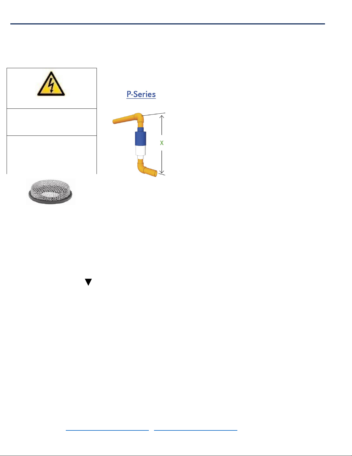
Important: Install a strainer screen, as shown in
Figure 1, over the drain inlet prior to operation of the
HVAC unit and before installing the trap. An integral
Union-Strainer™( see Figure 8) may also be
inserted in the drain line upstream of the Air-Trap.
1. Install the P-SERIES Air-Trap vertically with the
end marked “top” facing upward and the
embossed arrowhead, , pointing downward. This
is a requirement for proper movement of the
internal float valve component.
2. Install the trap in accordance with manufacturer’s
instructions and with all applicable local or national
plumbing, drainage, and mechanical codes.
3. NEVER CONNECT CONDENSATE DRAIN
DIRECTLY TO A SANITARY DRAIN LINE.
Connect only to a storm drain or a condensate
drain line.
Operation
The P-SERIES Air-Trap operates dry when no water
removal is required and wet when it is required. When
dry, essentially no air exits the HVAC unit. When
removing water, the water exits the unit, but essentially
no air exits the unit through the drain connection.
Install the P-SERIES Air-Trap in a vertical orientation.
With no production of condensate within the AHU the
positive pressure that exists within the plenum that
contains the drain line forces the capsule (or
spherocylinder), downward onto the valve seat. With
the production of water within the plenum, the capsule
rises from the seat when the net buoyancy force
upward equals or exceeds the net downward force
created by air pressure. See cutaway view in Figure
3. The standard model P-SERIES operates as a
positive trap up to 12 inches WG of positive pressure.
If a pressure of more than 12 inches WG could occur,
then please contact Des Champs Technologies for
information on the Engineered P-Series Air-Trap.
The P-SERIES Air-Trap accomplishes the following:
•Reduces sludge buildup that normally
accumulates in standard “P” traps
•Prevents freezing of trap during cold periods
since during periods of no water removal there
is no water in the trap. If, for some reason,
water is flowing from the unit during freezing
temperatures, and the trap is located within this
freezing temperature region, then the trap will
require thermal protection.
•P-Series Air-Trap requires no water head to
cause the trap to operate. Simply come out of
the plenum with the condensate line and go
down into the P-Series Air-Trap. Come out of
the trap and go horizontally with your drain line.
The height, x, requirement then becomes the
height of the trap plus two street elbows.See
Figure 2.
•Eliminates air escaping from an HVAC unit that
would result from a standard P-trap
experiencing a “dry-out” condition.
•Note: If there is a possibility of a syphoning
effect (suction pressure) at the exit point of the
Air-Trap then it is necessary to install a vent as
close as possible to the bottom of the trap (see
Figure 9).
•If height, x, is an issue, the P-Series Air-Trap
may be installed at a 45° angle, as shown in
Figure 5. When installed at a 45° angle, the
maximum positive pressure it can withstand is
5” of WG instead of 12”. The reduced pressure
capability is a result of a reduction in buoyancy.
•Another option when height is an issue is to
install the N-Series Air-Trap vertically, as
opposed to horizontally when used as a
negative trap, shown in Figure 6. The
maximum positive plenum pressure it
CAUTION
Failure to provide adequate
drainage piping may result in
water damage to equipment or
building.
Place stainless steel filter
screen, Figure 1 over drain
inlet or install a
Union-Strainer™, see Fig 8,
upstream of the trap.
Figure 1 Strainer Screen
Figure 2: P-Series Air-
Trap Installed

Des Champs Technologies | 2 Nikki Lane | Natural Bridge Station, VA 24579
www.deschampstechnologies.com | info@deschampstechnologies.com | Ph: 540-228-1967
Page | 3
Rev: 12/20
can withstand is 3” of WG. The cleanout port is on the
bottom when used for positive pressure.
Maintenance and Techniques for Cleaning the
P-Series Air-Trap
In some operations, particulate matter can move from
the HVAC unit through the drain line and into the
P-SERIES Air-Trap. The accumulation of particulate
matter in the trap may cause the trap to operate less
efficiently or fail. Therefore, a means to remove the
accumulated debris is required. A stainless steel filter
screen (Figure 1) over the drain inlet or a
Union-Strainer™ (Figures 7 & 8) within the drain line
extends the time between maintenance. Install the
Union-Strainer™ upstream of the Air-Trap.
There are several other options for cleaning.Option 1,
is to use the ½-inch cleanout port in the trap housing.
This will allow insertion of a water or air hose for
washing or blowing away material that may be
hampering operation of the trap. See Figure 3.
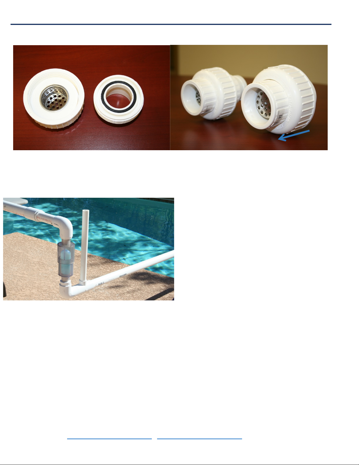
Option 2, shown in Figure 7, is to isolate the
P-SERIES Air-Trap from the main drain line by
installing unions that allow Air-Trap removal for
replacement or cleaning.
The best way to reduce maintenance is to install a
Des Champs Union-Strainer™ upstream of the
Air-Trap,(See Figure 8). The Union-Strainer™ is
also a convenient way to prevent unwanted creatures
and objects from entering the terminus of the drain line,
like snakes, rats, lizards, insects, and other
miscellanious items like, rocks, screws, and nuts. The
water flow is in direction of arrow shown in Figure 8,
with the strainer cup oriented to capture debris within
the cup.
Des Champs Technologies also offers engineered
traps for positive plenum pressure above 12 inches in
WG.Figure 4is a cut away view of an engineered
trap showing a cleanout port and the cylindrical float
that rises off the seat when condensate begins to
accumulate in the trap. Engineered Air-Traps are
designed for applications above the 12 inches of
positive pressure of the standard P-Series Air-Trap.
The Engineered Air-Trap can withstand positive
pressure up to 50” of WG or greater. Caution, do not
puncture the Float Valve.
Figure 3½-inch cleanout
port - Standard Model of P-
SERIES Air-Trap up to 12”
of positive pressure.
Figure 4 ¾-inch thread cleanout
plug- Engineered Model of P-
SERIES Air-Trap, for positive
pressure above 12” up to 50” WG.
Figure 5P-SERIES Air-Trap
installed at 45° angle can
reduce trap height by 30%
and operate at up to 5” of
positive pressure.
Figure 6N-SERIES Air-Trap
when installed vertically can
operate properly up to 3” of
positive pressure.
Threaded
plug for
cleaning
Threaded
plug for
cleaning
Figure 7 Use
unions to isolate
the Air-Trap for
removal or for
maintenance
Des Champs Technologies | 2 Nikki Lane | Natural Bridge Station, VA 24579
www.deschampstechnologies.com | info@deschampstechnologies.com | Ph: 540-228-1967
Page | 4
Rev: 12/20
Figure 8 In-line Union-Strainers. Install in the drain line
upstream of the Air-Trap. This will aid in preventing
debris from entering trap.
Figure 9 Installation of a Vertical Vent Pipe installed
directly downstream of a P-Series Air-Trap to prevent a
suction pressure from developing below the trap. A
suction pressure could develop depending upon the
length of drainpipe, the diameter, and the water flow
rate.
Inspect the P-Series Air-Trap on an annual basis;
remove any sludge or foreign materials that might
obstruct proper operation of the internal mechanism or
general drainage of the drain line. Remove obstacles
utilizing the clean out port located at the bottom of the
Air-Trap. Caution – do not damage the internal
mechanism inside the P-Series Air-Trap. Properly
dispose of any contaminated materials.
,
Limited Warranty
.
Des Champs Technologies warrants to the original consumer
purchaser (“Purchaser”) of its product, P-SERIES Air-Trap,
that it is free from defects in material or workmanship. If
within the 12-month period from the date of the original
consumer purchase this product shall prove to be defective,
it shall be repaired or replaced at Des Champs Technologies
option. Your original receipt of purchase is required to
determine warranty eligibility. The warranty does not cover
damage due to misuse, misapplication, lack of maintenance,
or failure to comply with the manufacturer’s installation
instructions or recommendations or any other loss or damage
exceeding the purchase price of the equipment purchased
from Des Champs Technologies. Des Champs Technologies
assumes no responsibility for damage or injury resulting
from chemical incompatibility between its products and the
process fluids to which they are subjected. This warranty is
limited to repair or replacement of the P-SERIES Air-Trap
only and is the only warranty issued by Des Champs
Technologies on its trap products.
This product design is Patented by Des Champs
Technologies LLC, Natural Bridge Station, Virginia
24579.
Des Champs Technologies also has a full line of
Commercial grade Negative Pressure Traps. Call or
go to the Website below for more information.
Figure 8: Union-
Strainers™,


