meier elektronik AGRO PILOT User manual
Operating Instructions
Page 1 of 32
Meier Elektronik AG –Gewerbezone 61 –6018 Buttisholz –Tel. 041 497 31 04 –Fax. 041 497 35 07
Agricultural Radio Control
Document Version: 2.4
Author: M. Kurmann
Update History
Date
Version
Description
05/14/2012
0.1
First draft
07/09/2012
0.2
Dimensions receiver/adapter plate adjusted
07/13/2012
1.0
Sender labeling adjusted
07/25/2012
1.1
Fig. 12 (sample connection to 400VAC revised to be clearer)
09/28/2012
1.2
Yagi antenna installation added
10/03/2012
2.0
Release after testing for CE conformity
11/05/2012
2.1
Description of the "integrated Telepilot" option
11/30/2012
2.2
Description of the "remote antenna" option (ModemPilot)
02/22/2013
2.3
Description of individual configuration of connection between
receiver and laptop
10/16/2019
2.4
Adaptation of the CE declaration of conformity after RED
remeasurement
AGROPILOT

Operating Instructions
Page 2 of 32
Meier Elektronik AG –Gewerbezone 61 –6018 Buttisholz –Tel. 041 497 31 04 –Fax. 041 497 35 07
Contents
1Introduction....................................................................................................................................... 3
2Safety Notices .................................................................................................................................. 4
3Hand-Held Transmitter..................................................................................................................... 5
3.1 Installation................................................................................................................................ 5
3.2 General Functions ................................................................................................................... 5
3.3 Changing Batteries.................................................................................................................. 5
4Integrated TelePilot.......................................................................................................................... 6
4.1 General.................................................................................................................................... 6
4.2 Operation................................................................................................................................. 7
5Receiver ........................................................................................................................................... 8
5.1 How to Install the Receiver Housing ....................................................................................... 8
5.2 How to install the Antenna..................................................................................................... 11
5.3 Installation.............................................................................................................................. 13
5.4 Sample Receiver Connections.............................................................................................. 16
5.4.1 Sample connection to 400 V~ with contactor and motor................................................... 16
5.4.2 For connection to 400 V~ star-delta control ...................................................................... 17
5.4.3 Sample connection to 12V- with relay board for V-belt coupling....................................... 18
5.4.4 Sample connection to 12V for magnetic coupling ............................................................. 19
5.5Putting into Service................................................................................................................ 20
5.6 Establishing a Connection between the Receiver and a Laptop/PC..................................... 21
5.6.1 Configuring an LAN Connection........................................................................................ 21
5.6.2 Connecting a Laptop/PC to the Receiver.......................................................................... 22
5.6.3 Configuring the Radio Receiver......................................................................................... 23
5.7 Table of Functions................................................................................................................. 24
6Changing the Frequency................................................................................................................ 25
7Replacing the Fuse ........................................................................................................................ 26
8Troubleshooting.............................................................................................................................. 27
9Error Codes.................................................................................................................................... 28
10 Intended Use of this Device....................................................................................................... 28
11 Specifications............................................................................................................................. 29
12 CE Conformity ........................................................................................................................... 31
13 EMV measurements.................................................................................................................. 32

Operating Instructions
Page 3 of 32
Meier Elektronik AG –Gewerbezone 61 –6018 Buttisholz –Tel. 041 497 31 04 –Fax. 041 497 35 07
1 Introduction
The AgroPilot radio system consists of a transmitter and a receiver. Communication takes place
mainly from the transmitter to the receiver. With the "feedback" option, the relay states can be
displayed on the transmitter.
Thanks to sophisticated wireless technology, distances of up to several kilometers can be achieved
(line of sight).
In addition, the receiver has an integrated PLC (CoDeSys) that allows more complex linkages to be
established. The PLC functionality is optional and is only enabled upon request.
The handheld transmitter features 12 robust, water- and weather-proof silicone buttons that provide
comfortable tactile feedback. They are backlit and indicate the relay status of each function. The
robust, high-quality laser labeling can be customized.
Depending on the model, the receiver features 2, 4, 6 or 7 relay outputs and includes an integrated
buzzer. The relays can be programmed by touch, resting, to switch off after a certain time or to
prevent switching off. If the PLC option has been enabled, as many separate linkages and delays as
desired can be implemented.

Operating Instructions
Page 4 of 32
Meier Elektronik AG –Gewerbezone 61 –6018 Buttisholz –Tel. 041 497 31 04 –Fax. 041 497 35 07
2 Safety Notices
The received must be installed, serviced and set up only by trained electricians.
All installation and safety standards must be followed.
Before putting into service, check whether the correct operating voltage has been set in
terms of performance and voltage (see receiver model label).
The switches must not be operated ungrounded.
The receiver terminal box may only be opened once the current has been cut off.
Never work on the terminals or controls when the current is active!
Never wash the unit with water or clean with high pressure water.
The AgroPilot radio remote control must NOT be used in applications where failure or
malfunction of the product could result in personal injury or material damage.
Operating Instructions
Page 5 of 32
Meier Elektronik AG –Gewerbezone 61 –6018 Buttisholz –Tel. 041 497 31 04 –Fax. 041 497 35 07
3 Hand-Held Transmitter
3.1 Installation
The transmitter is delivered with 3 pre-installed AA alkaline batteries and is ready to use without
further preparation.
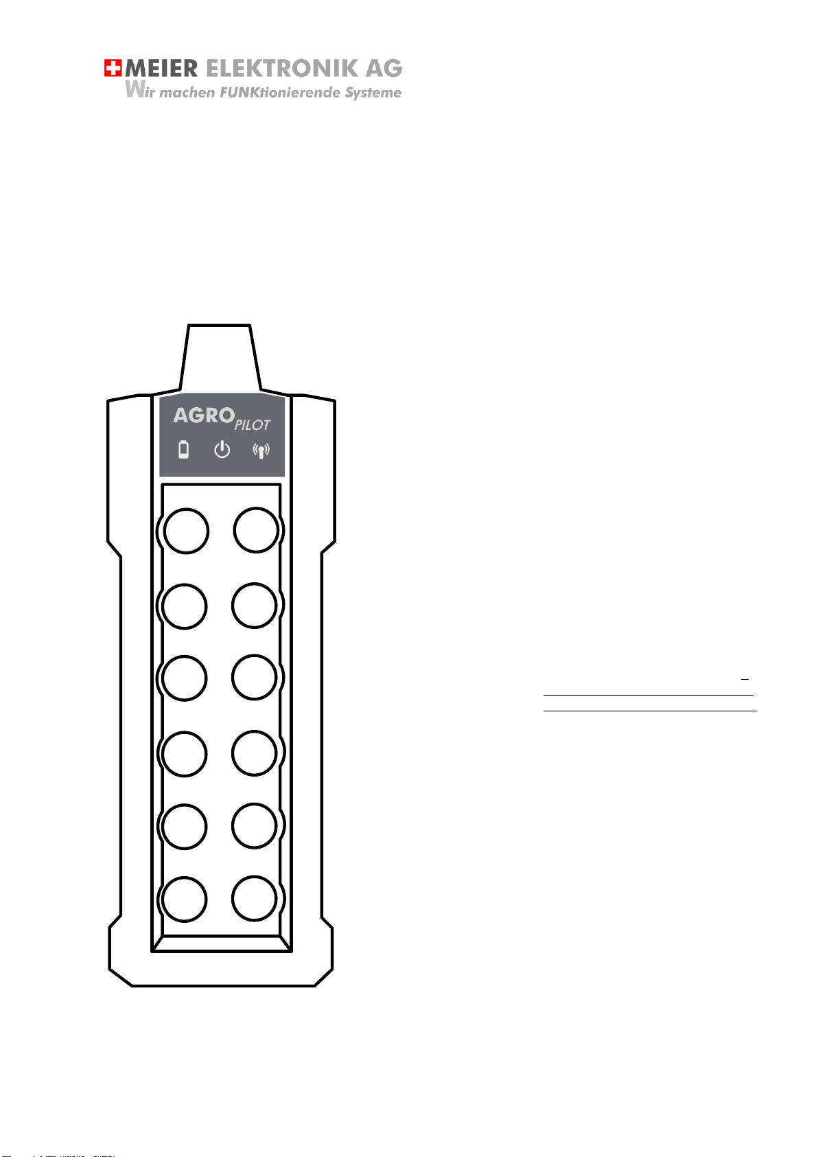
3.2 General Functions
Fig. 1: Front Side of Transmitter
LED display:
A: Low battery status
(if lit, change battery)
The LED will flash as the battery is
getting low, but the transmitter will
continue operating for some time. If
the LED stays lit (without blinking),
the batteries must be changed.
B: Transmitter on
(if lit, indicates the
transmitter is ready to
operate)
The LED lights up when a button is
pressed to indicate that the
transmitter is ready to use. After
approx. 15 seconds without further
input from the user, the transmitter
will return to standby mode. The
LED will flash to indicate this.
C: Wireless connection
(displays quality of wireless
connection)
If the LED flashes quickly, this
indicates communication between
the transmitter and the receiver. If
the LED stays lit (without blinking),
the connection has been disrupted.
Button:
1: Pump on
2: Pump off
3: Water valve
4: Liquid fertilizer valve
5: Return on
6: Return off
7: Agitator on
(only on Model 6K)
8: Agitator off
(only on Model 6K)
9: Reserve on
(only on Model 6K)
10: Reserve off
(only on Model 6K)
11: Transmitter on
(hold for at least 1 sec.)
12: Buzzer
3.3 Changing Batteries
Remove the battery housing cover on the back of the transmitter to reach the battery compartment
and the manufacturer interfaces.
12
34
56
78
910
11 12
A B C

Operating Instructions
Page 6 of 32
Meier Elektronik AG –Gewerbezone 61 –6018 Buttisholz –Tel. 041 497 31 04 –Fax. 041 497 35 07
For the machine to work properly, use standard AA, 1.5V alkaline batteries.
The batteries can be ordered from Firma Meier Elektronik AG or from a
specialist store.
Fig. 2: Rear Side of Transmitter
1: Device number
Each transmitter/receiver pair
has a unique device number.
The device numbers for the
transmitter and receiver must be
identical.
2: Frequency selector
A maximum of 8 different
frequencies are available. If you
change the frequency with the
dial, do the same on the
receiver.
3: Programming interface
Manufacturer's programming
interface (not used by end
users)
4: Batteries
3 AA (1.5V) alkaline batteries
5: Configuration interface
Manufacturer's USB
configuration interface (not used
by end users)
4 Integrated TelePilot
4.1 General
If AgroPilot contains the optional integrated TelePilot, the controller can be accessed globally. This
allows issues with the range of radio signals to be easily bridged. This feature requires a telephone
(mobile or landline).
01
2
3
4
5
6
7
AA AA AA
23
4
5
00234
1

Operating Instructions
Page 7 of 32
Meier Elektronik AG –Gewerbezone 61 –6018 Buttisholz –Tel. 041 497 31 04 –Fax. 041 497 35 07
4.2 Operation
Use your phone to dial the number of the receiver housing and use the phone's keypad to turn
features/channels on or off. With * (star), you can switch a feature ON. With the # (pound sign), you
can switch it OFF, if it is bistable. Momentary functions (such as the buzzer) turn themselves off.
Table 1: Overview of TelePilot Functions:
Pump ON
1*
Pump OFF
1#
Open water valve
2*
Liquid fertilizer valve
2#
Return on
3*
Return off
3#
Agitator on
4*
Agitator off
4#
Reserve on
5*
Reserve off
5#
Buzzer
8* (turns itself off)

Operating Instructions
Page 8 of 32
Meier Elektronik AG –Gewerbezone 61 –6018 Buttisholz –Tel. 041 497 31 04 –Fax. 041 497 35 07
5 Receiver
5.1 How to Install the Receiver Housing
The receiver housing has a stable aluminum mounting plate on the rear side that allows for different
installation options. Depending on the installation option, the receiver can be mounted on the DIN
track, brackets, a rubber buffer or by magnet.
Fig. 3: Receiver Housing with Mounting Plate
If the receiver is used outdoors, it should not be exposed to direct weather
influences which will unnecessarily reduce its useful life.
Protect the receiver from spraying water and other environmental influences
222
1
8
5
9
208
1
2
5
106
25
5
Receiver
Mounting Plate
L
1
L
2
PE
12 11 14
CH
1
12 11 14
CH
2
12 11 14
CH
3
12 11 14
CH
4
12 11 14
CH
5
12 11 14
CH
6
12 11 14
CH
7
12 11 14
CH
8

Operating Instructions
Page 9 of 32
Meier Elektronik AG –Gewerbezone 61 –6018 Buttisholz –Tel. 041 497 31 04 –Fax. 041 497 35 07
Fig. 4: Receiver Mounting Plate
Table 2: Receiver Mounting Options
Fastening
Description
1
Fastening with brackets. 4 brackets are included if ordered.
2
Fastening with DIN brackets. 2 DIN brackets are included if ordered.
3
Fastening with rubber buffers. 4 rubber buffers are included if ordered.
4
Fastening with magnets. 4 magnets are included if ordered.
5
Individual mounting options
1
1
1
1
1
1
2
2
2
2
3
3
3
3
4
4
4
4
4
5

Operating Instructions
Page 10 of 32
Meier Elektronik AG –Gewerbezone 61 –6018 Buttisholz –Tel. 041 497 31 04 –Fax. 041 497 35 07
Fig. 5: Dimensions of the Receiver Mounting Plate
222
185
10 170
11
142
55
10
148
60
50
207
14
Operating Instructions
Page 11 of 32
Meier Elektronik AG –Gewerbezone 61 –6018 Buttisholz –Tel. 041 497 31 04 –Fax. 041 497 35 07
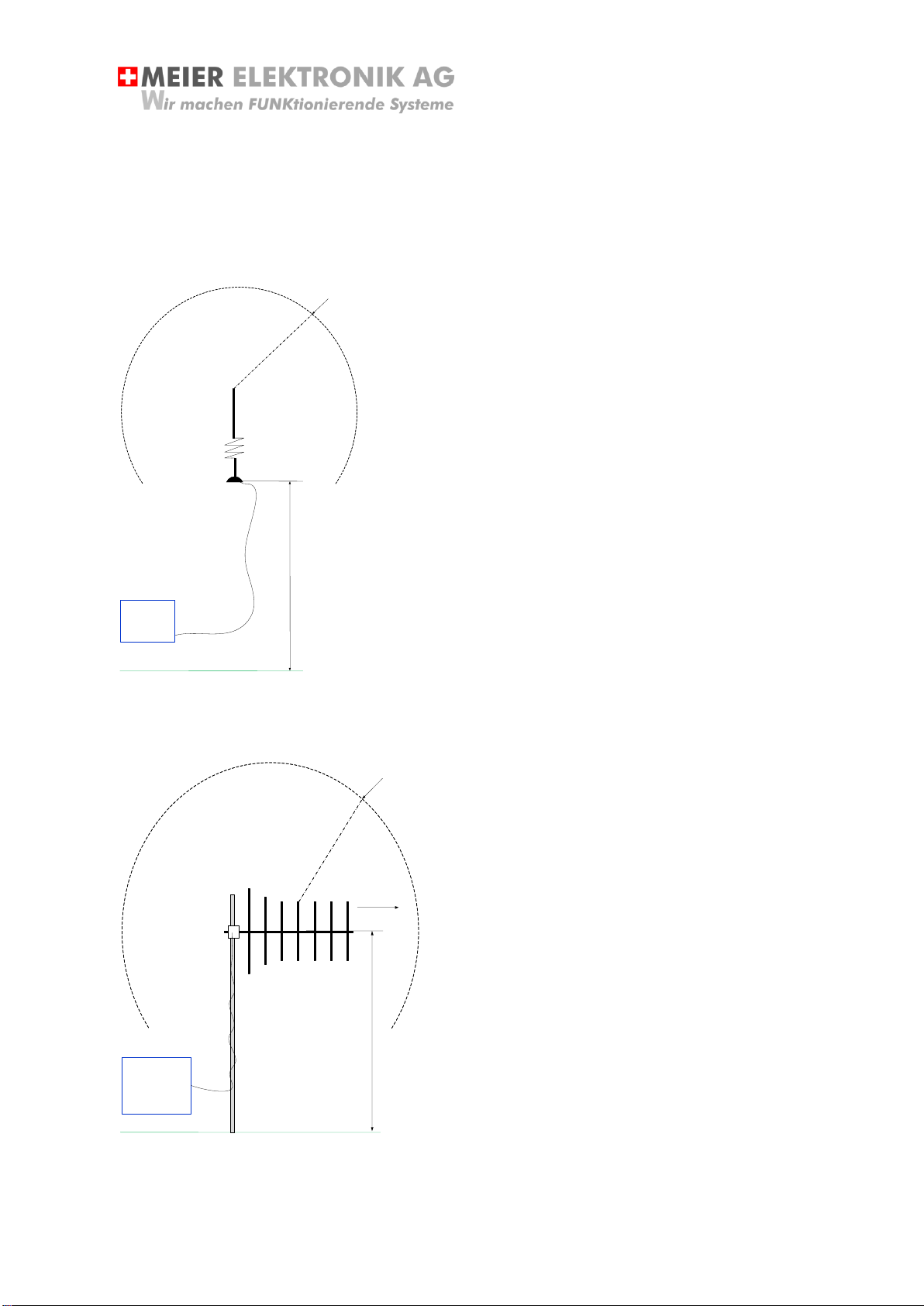
5.2 How to install the Antenna
Reception is best if in a direct line of sight. Because this is usually not possible, the receiving antenna
must be positioned so that it can send or receive signals on its own.
Fig. 6: Standard Antenna Installation
It is ideal when there are no obstacles blocking
the antenna for 2-3 meters. In addition, the
reception quality can be increased if the
antenna is mounted 2-3 feet above the ground.
Set the magnetic mount antenna on a metal
bracket. The metal bracket then servers as the
counter-potential and also contributes
significantly to improving the antenna's range.
Fig. 7: Installing the Yagi Antenna
It is ideal when there are no obstacles
blocking the antenna for 2-3 meters. In
addition, the reception quality can be
increased if the antenna is mounted 2-3 feet
above the ground.
The antenna is to be mounted insulated on a
metal rod. Ideally, use a wooden pole.
The entire installation material (antenna,
antenna cable and antenna masts) can be
obtained from Meier Elektronik AG!
Radio receiver
2
meters
2
-
3
meters
Antenna
ground
Radio receiver
2
meters
2
-
3
meters
Antenna
ground
Radio direction
Operating Instructions
Page 12 of 32
Meier Elektronik AG –Gewerbezone 61 –6018 Buttisholz –Tel. 041 497 31 04 –Fax. 041 497 35 07
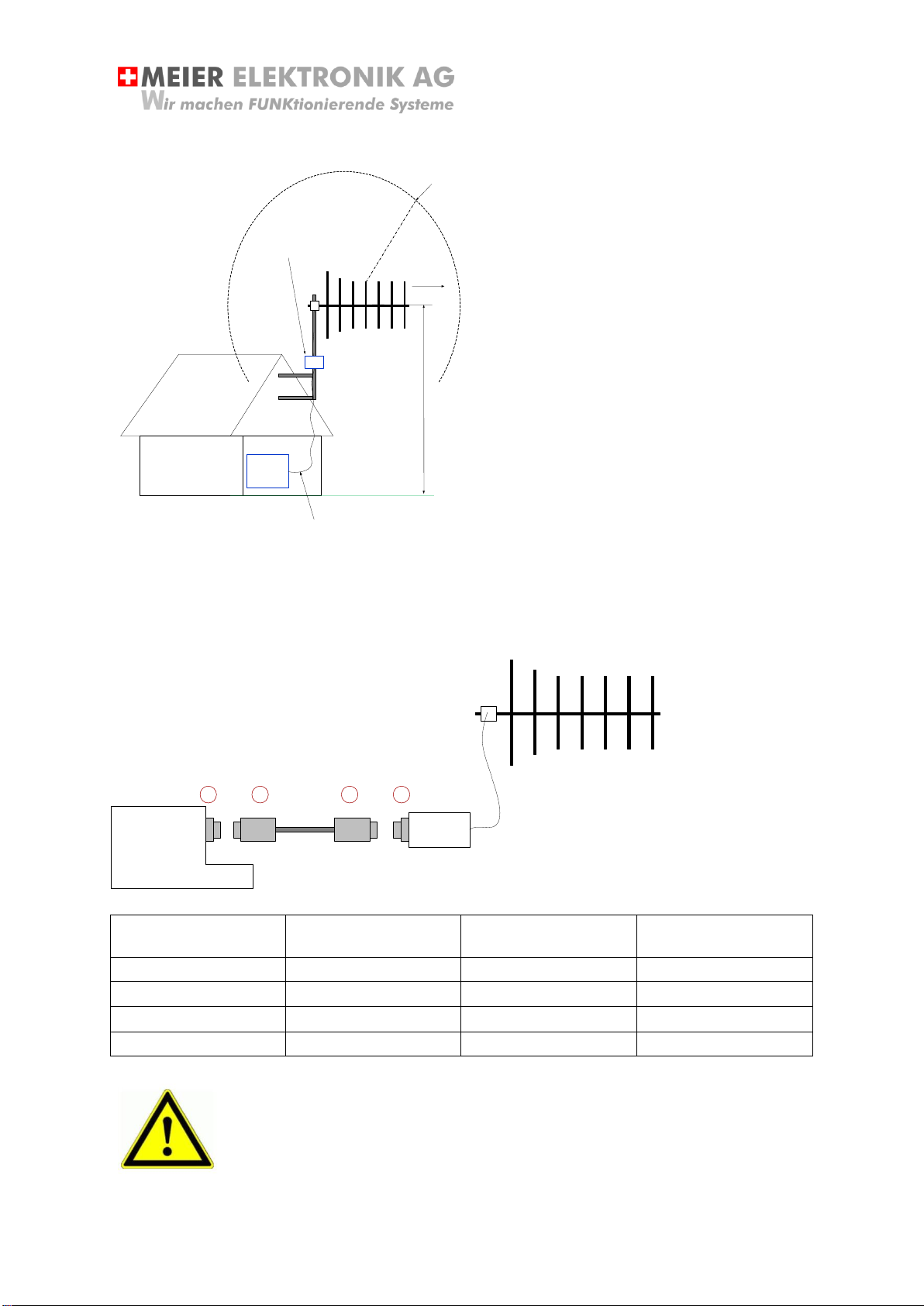
Fig. 8: Installing the Remote ModemPilot Antenna
If the radio receiver via an
active external antenna
(ModemPilot), the antenna
can be mounted up to 50m
from the receiver. The
antenna should be mounted
as high as possible and free
of obstructions.
The remote antenna (ModemPilot) is connected via four 0.14mm2bus cables to the receiver. The
cable can be inserted on both sides and wired 1:1. If you opt to configure your own cable, the
connections are 1:1 or as follows:
Fig. 9: Connecting the Remote ModemPilot Antenna
Receive Female
Round Male
Connector Cable
Round Female
Connector Cable
Male ModemPilot
Pin 1
Pin 1
Pin 1
Pin 1
Pin 2
Pin 2
Pin 2
Pin 2
Pin 3
Pin 3
Pin 3
Pin 3
Pin 4
Pin 4
Pin 4
Pin 4
The antenna should always be mounted potential-free. It should not be
grounded or mounted to a vehicle chassis!
The antenna mast may be made of metal, however, the mast must be attached
to wood or another insulated material.
Radio receiver
2
meters
10
-
20
meters
Antenna
ground
Radio direction
Antenna bus cable
-
ModemPilot
Antenna
1
2
3
4
Operating Instructions
Page 13 of 32
Meier Elektronik AG –Gewerbezone 61 –6018 Buttisholz –Tel. 041 497 31 04 –Fax. 041 497 35 07
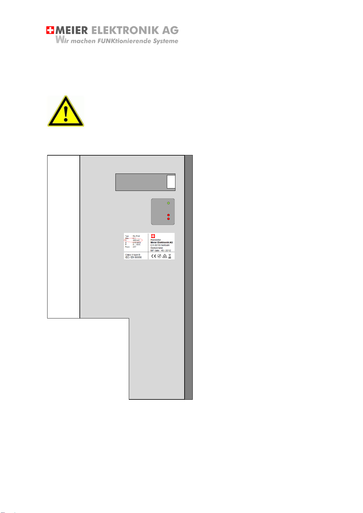
5.3 Installation
Before placing the receiver into operation, it must first be connected to the power supply and the relay
outputs must be wired.
Compare the voltage listed on the receiver nameplate with your operating
voltage (see Fig. 10 –Point 3).
Fig. 10: Receiver Labeling
1: Device
number
2: Power LED
Power
Radio
Error
3: Nameplate
Each
transmitter/receiver
pair has a unique
device number. The
device numbers for
the transmitter and
receiver must be
identical.
Shows the operating
status of the device.
If the device is
switched on, the
green LED (Power)is
lit.
If the receiver is
sending and receiving
messages correctly,
the Radio LED
flashes.
If the device is not
operating properly or
at all, a code
indicating the potential
cause will flash via the
Error LED. Refer to
the error code list on
Page 28 / Table 9.
General information
about the device,
such as operating
voltage, fuse, power
and frequency.
00234
MEIER ELEKTRONIK AG
6016 Hellbühl –041 497 31 04 1
2
3
Power
Radio
Error

Operating Instructions
Page 14 of 32
Meier Elektronik AG –Gewerbezone 61 –6018 Buttisholz –Tel. 041 497 31 04 –Fax. 041 497 35 07
Table 3: Connecting the Various Receiver Power-Supply Voltages
400V~
230V~
9 to 18VDC
18 to 36VDC
Phase 1 L1
Phase 2 L2
Ground PE
Phase 1 L1
Neutral N
Ground PE
9 to 18V +
GND / 0V -
Ground PE
18 to 36V +
GND / 0V -
Ground PE
The receiver supports a maximum of 8 high-quality relay channels. The
contacts are potential-free and always run SPDT relays (NC/NO
contacts).
The NC contact is at pin 12/11 and the NO contact is at pin 11/14.
The maximum switching voltage of the relays is 400V~ and is specially
approved for this area!
The relay can operated 1-phase motors directly with a load of up to
0.3W at 230V!
Use a #1 flat-headed
screwdriver to make
the connection.
DO NOT use wire
end ferrules at the
receiver connection
cable!
The cables will only
make the optimal
connection without
ferrules!
Pressing the notch on the front will open the press connection to allow
the cables to be inserted. The upper and lower wire connection are
electrically connected to each other.
Use only one wire per connector!
L1 L2 PE
L1 N PE
+ - PE
9..18VDC
+ - PE
18..36VDC
12 11 14
CH1
Operating Instructions
Page 15 of 32
Meier Elektronik AG –Gewerbezone 61 –6018 Buttisholz –Tel. 041 497 31 04 –Fax. 041 497 35 07
Table 4: Relay Specifications
Max. continuous current / max. starting current [A]
8 / 15
Rated voltage / max. switching voltage [V~]
230 / 400V
Rated load AC1 [VA]
2000
Rated load AC15 (230 V~) [VA]
400
1-phase motor load, AC3 operation (230V~) [kW]
0.3
Max. switching current DC1: 30/110/220V [A]
8 / 0.3 / 0.12
Min. switching load [mW, V/ mA]
300, 5/5
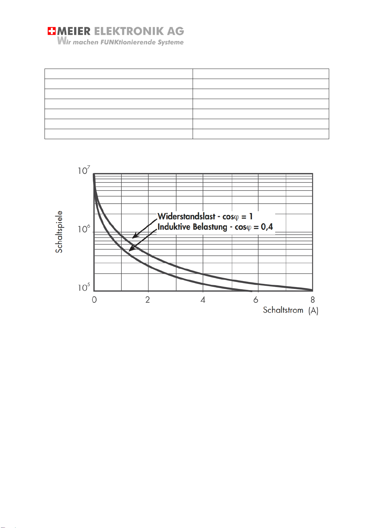
Fig. 11: Electrical Service Life with AC
Schaltspiele = switching cycles
Schaltstrom = switching current
Widerstandslast = resistance load
Induktive Belastung = inductive load

Operating Instructions
Page 16 of 32
Meier Elektronik AG –Gewerbezone 61 –6018 Buttisholz –Tel. 041 497 31 04 –Fax. 041 497 35 07
5.4 Sample Receiver Connections
5.4.1 Sample connection to 400 V~ with contactor and motor
Fig. 12: Sample connection to 400 V~ with contactor and motor
12 11 14
CH
1
L
1
L
2
PE
L
1
L
2
L
3
PE
I
>
I
>
I
>
……
.
Radio receiver
contactor
400
V
~
F
1
KM
1
M
1
4
kW
Motor

Operating Instructions
Page 17 of 32
Meier Elektronik AG –Gewerbezone 61 –6018 Buttisholz –Tel. 041 497 31 04 –Fax. 041 497 35 07
5.4.2 For connection to 400 V~ star-delta control
Fig. 13: For connection to 400 V~ star-delta control
12 11 14
CH1
L1 L2 PE
L1
L2
L3
PE
…….
Funkempfänger
Stern-Dreieck Steuerung
M1
L1
L2
L3
PE
U1
V1
W1
U2
V2
W2
PE
1
2
3
PE
4
5Klixon
Funk
Motor
Motor
Einspeisung

Operating Instructions
Page 18 of 32
Meier Elektronik AG –Gewerbezone 61 –6018 Buttisholz –Tel. 041 497 31 04 –Fax. 041 497 35 07
5.4.3 Sample connection to 12V- with relay board for V-belt coupling
Fig. 14: Sample connection to 12V- with relay board for V-belt coupling
12 11 14
CH
1
+
-
+
12
V DC
0
V
(
GND
)
……
.
Radio Receiver
1
1
1
2
9
1
0
7
8
1
3
1
4
1
5
1
6
5
2
1
6
4
3
M
12
V
-
E
n
d
s
c
h
a
l
t
e
r
O
b
e
n
E
n
d
s
c
h
a
l
t
e
r
U
n
t
e
n
(
i
m
m
e
r
z
u
,
s
o
l
a
n
g
e
K
e
i
l
r
i
e
m
e
n
i
.
O
)
P
u
m
p
e
A
u
s
/
E
i
n
E
n
d
s
c
h
a
l
t
e
r
M
i
t
t
e
Elektrozylinder
Keilriemen spannen
Relay board AP
-
KC
-
-
+
+
M
-
M
+

Operating Instructions
Page 19 of 32
Meier Elektronik AG –Gewerbezone 61 –6018 Buttisholz –Tel. 041 497 31 04 –Fax. 041 497 35 07
5.4.4 Sample connection to 12V for magnetic coupling
Fig. 15: Sample connection to 12V for magnetic coupling
If the magnet coupling pin is removed, the protective cover must be mounted
on the bushing to protect the contacts against environmental influences. This
will increase the useful life of the connector.
Table 5: Pin Assignment for Magnetic Coupling
Pin Number
Description
1
Switched + via relay 1 (+12 V)
2
Switched + via relay 1 (+12 V)
3
GND / minus
GND / minus
12 11 14
CH
1
+
-
+
12
V DC
0
V
(
GND
)
……
.
Radio receiver
1 2
3
CH
1
/
Relais
1
max
.
16
A
Current load
(
Magnetic coupling)
Female Magnetic Coupling

Operating Instructions
Page 20 of 32
Meier Elektronik AG –Gewerbezone 61 –6018 Buttisholz –Tel. 041 497 31 04 –Fax. 041 497 35 07
5.5 Putting into Service
1. When switching on the power to the receiver, all
three operating LEDs (Power, Radio, Error) will
initially be lit.
2. After about 8 seconds, the Radio and Error LEDs
will switch off for about 3 seconds.
3. Then, the Radio and Error LEDs will flash for 1
second and, if the GSM modem is installed, for
about 6 seconds.
4. After successfully going through this start-up
routine, the Radio and Error LEDs switch off and
only the Power LED remains lit.
5. The device is now ready for use.
6. If the transmitter is functioning correctly, when you
press a button on it, the feedback will be actuated
on the transmitter and you can start working with
the device.
If the device is not operating properly or at all, a code indicating the potential cause will flash via the
Error LED. Refer to the error code list in Table 9, p.28
00234
MEIER ELEKTRONIK AG
6016 Hellbühl –041 497 31 04 1
2
3
Power
Radio
Error
Table of contents
Popular Remote Control manuals by other brands


XPPen
XPPen ACK05 user manual

dewert okin
dewert okin RF-APLINE quick guide

One Forall
One Forall URC-3435 instruction manual

FRONIUS
FRONIUS RCU 4000 operating instructions

SHENZHEN GUIYUAN INDUSTRY DEVELOPMENT
SHENZHEN GUIYUAN INDUSTRY DEVELOPMENT Z-06 quick start guide

Elite
Elite TH0471 instruction manual