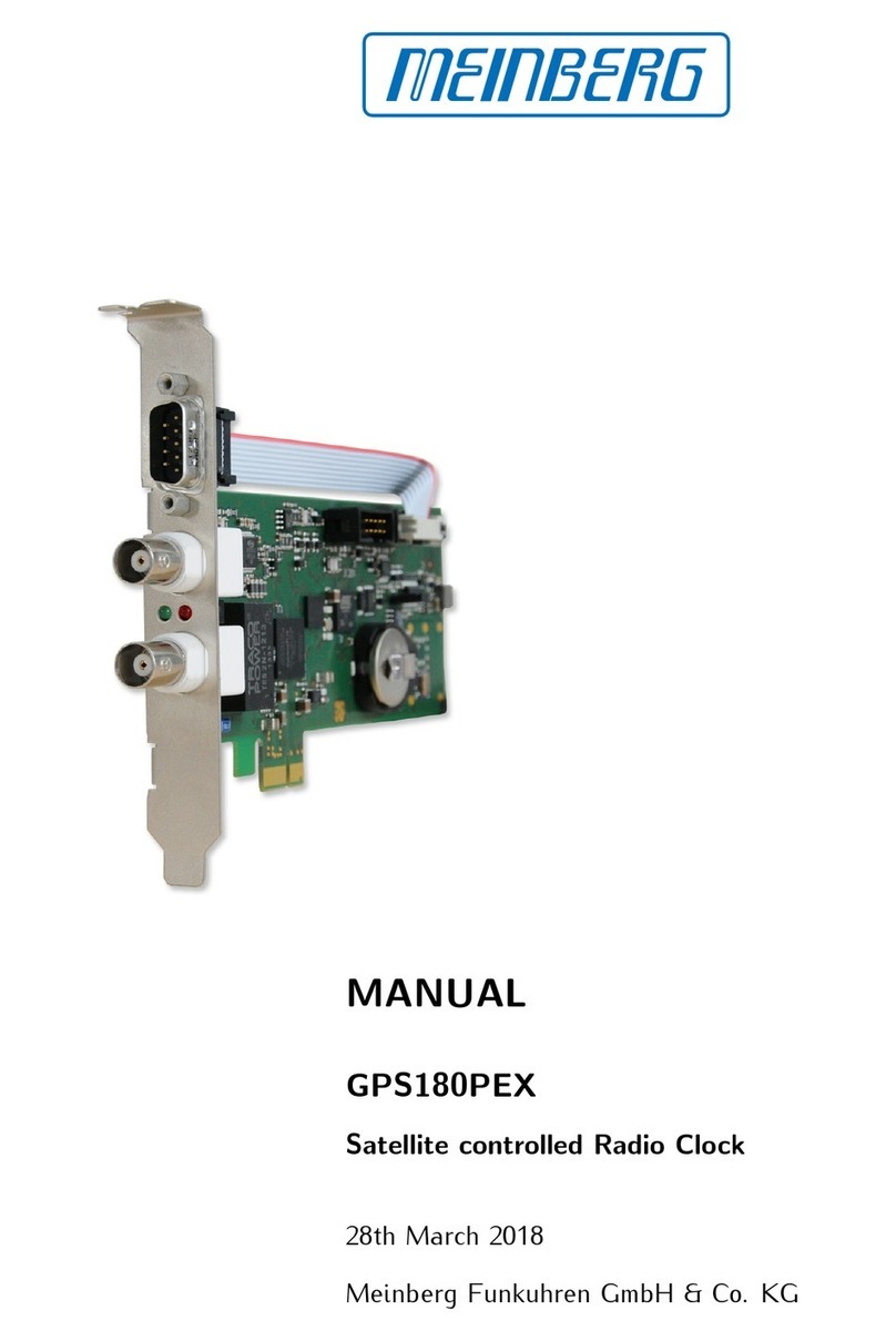
Meinberg IMS-GPS182 User manual

SETUP GUIDE
IMS-GPS182
Hot-Plug Module
June 16, 2022
Meinberg Funkuhren GmbH & Co. KG


Table of Contents
1 Imprint 1
2 Change Log 2
3 Introduction 3
4 Important Safety Information 4
4.1 ProductDocumentation ........................................... 4
4.2 PreventionofESDDamage......................................... 5
4.3 PowerSupply................................................. 6
4.4 HandlingofBatteries ............................................ 6
4.5 Cabling..................................................... 7
5 IMS-GPS182 Variants 8
6 IMS-GPS182 Module Connectors and LEDs 10
6.1 Status-LEDs ................................................. 11
6.2 COMxTimeString:RS-232 ........................................ 12
6.3 XHE-SPI ................................................... 12
6.4 Antenna Input: GPS Reference Clock . . . . . . . . . . . . . . . . . . . . . . . . . . . . . . . . . . . 13
7 Before You Start 14
7.1 ContentsofDelivery............................................. 14
7.2 DisposalofPackagingMaterials...................................... 14
8 Installation of the GPS Antenna 15
9 System Installation 20
9.1 Important Information Regarding Hot-Pluggable IMS Modules . . . . . . . . . . . . . . . . . . . . 20
9.2 Installation of Hot-Pluggable IMS Modules. . . . . . . . . . . . . . . . . . . . . . . . . . . . . . . . 21
9.3 DataandSignalCables........................................... 22
10 Configuration and Status Monitoring 23
10.1RequiredConfiguration ........................................... 23
11 Troubleshooting 26
12 Technical Appendix: GPS Antenna + Accessories 27
12.1AntennaCable ................................................ 29
12.2AntennaShortCircuit ............................................ 29
12.3 Technical Specifications: MBG S-PRO Surge Protection . . . . . . . . . . . . . . . . . . . . . . . 30
12.3.1 MBG S-PRO: Physical Dimensions . . . . . . . . . . . . . . . . . . . . . . . . . . . . . . . 32
12.3.2 InstallationandGrounding..................................... 32
13 How Satellite Navigation Works 33
13.1 Time Zones and Daylight Saving Time . . . . . . . . . . . . . . . . . . . . . . . . . . . . . . . . . . 34
14 Your Opinion Matters to Us 35
15 RoHS and WEEE 36
16 List of Abbreviations 37
Date: June 16, 2022 IMS-GPS182

1 Imprint
1 Imprint
Meinberg Funkuhren GmbH & Co. KG
Lange Wand 9, 31812 Bad Pyrmont, Germany
Phone: + 49 (0) 52 81 / 93 09 - 0
Fax: + 49 (0) 52 81 / 93 09 - 230
Website: https://www.meinbergglobal.com
Email: [email protected]
Date: March 8, 2022
Manual
Version: 1.0
IMS-GPS182 Date: June 16, 2022 1

2 Change Log
Version Date Revision Notes
———————————————————————————————————————————————
1.0 02/15/2022 Initial version
———————————————————————————————————————————————
2 Date: June 16, 2022 IMS-GPS182
3 Introduction
3 Introduction
This Setup Guide is a systematically structured guideline to assist you with the set-up of your Meinberg product.
The IMS-GPS182 is a 12-channel satellite clock module with GPS technology that has been developed from
the ground up specifically for time and frequency synchronization purposes. The IMS-GPS182 provides a high-
precision, high-accuracy time and frequency reference for your Meinberg IMS system and is designed to receive
signals from the U.S. Global Positioning System (GPS), allowing your Meinberg system to be used anywhere
in the world.
Features
Once the IMS-GPS182 is successfully initialized and synchronized, it distributes a 1PPS (pulse per sec-
ond) reference clock signal and a 10 MHz reference frequency, both of which are critical in determining the
precision and accuracy of the output signals.
The IMS-GPS182 module provides the basis for which the IMS output modules generate a wide variety of
specific output signals used in a diverse range of applications.
Use of Two IMS-GPS182 Modules
In systems equipped with two IMS-GPS182 modules, an RSC switchover module is used to switch between the
two reference sources. The RSC serves to switch over the pulse and frequency outputs and serial interfaces of
the connected reference clocks.
Please refer to the LANTIME Firmware Manual for a more detailed description of all of the status moni-
toring configuration options and features available for your Meinberg product.
LTOS7 Firmware Manual Download:
http://www.mbg.link/docg-fw-ltos
Compatibility
The IMS-GPS182 is an IMS module that is compatible with the following systems in the IMS product family
and can be used in the following slots:
PWR
CLK
CPU
MRI
ESI
I/O
M500
M1000
M1000 S
M2000 S
M3000
M3000 S
M4000
System Compatibility - IMS GPS182
IMS System
Compatible
Compatible
IMS Slot
Slot Compatibility - IMS GPS182
To eliminate any risk of compatibility problems, your IMS system should have at least LANTIME OS Version
7.04 installed.
IMS-GPS182 Date: June 16, 2022 3

4 Important Safety Information
Please ensure that IMS modules designed for "hot-plugging" (modules that are removable and insertable while
a system is in operation) are always handled with the utmost care.
Before performing any maintenance work on the system, Meinberg recommends:
•backing up stored configurations (e.g., via USB flash drive or the Web Interface)
•taking note of the chapter "Prevention of ESD Damage".
•taking note of the chapter "Power Supply".
4.1 Product Documentation
Detailed product documentation is provided on a USB flash drive delivered with the Meinberg system. The
manuals can also be downloaded from the Meinberg website at https://www.meinbergglobal.com, where you can
enter your system name into the search box at the top of the page to find the relevant manual. Alternatively,
contact Meinberg Support for further assistance.
The "Docs & Support" menu on the Web Interface also provides user manuals for time server administrators.
This manual contains important safety instructions for the installation and operation of the
device. Please read this manual thoroughly before using the device.
This device may only be used for the purpose described in this manual. In particular, the
specified operating limits of the device must be heeded. The person setting up the device is
responsible for safety matters in relation to any larger system in which the device is
installed!
Failure to observe these instructions may have an adverse impact on device safety!
Please keep this manual in a safe place.
Target Readership
This manual is only intended to be used by qualified electricians, or by persons who have been appropri-
ately instructed by a qualified electrician and who are familiar with applicable national standards and with
safety rules & regulations. This device may only be installed, set up, and operated by qualified personnel.
4 Date: June 16, 2022 IMS-GPS182

4 Important Safety Information
4.2 Prevention of ESD Damage
ATTENTION!
An ESDS device (electrostatic discharge-sensitive device) is any device at risk of damage or
malfunction due to electrostatic discharges (ESD) and thus requires special measures to prevent
such damage or malfunction. Systems and modules with ESDS devices usually bear the following
symbol:
Symbol Indicating Devices with ESDS Components
The following measures will help to protect ESDS components from damage and malfunction.
When preparing to dismantle or install devices:
Ground your body (for example, by touching a grounded object) before touching sensitive devices.
Ensure that you wear a grounding strap on your wrist when handling such devices. These straps must
in turn be attached to an uncoated, non-conductive metal part of the system.
Use only tools and devices that are free of static electricity.
When transporting devices:
Devices must only be touched or held by the edges. Never touch any pins or conductors on the device.
When dismantling or installing devices:
Avoid coming into contact with persons who are not grounded. Such contact may compromise your
connection with the earth conductor and thus also compromise the device’s protection from any
static charges you may be carrying.
When storing devices:
Always store devices in ESD-proof ("antistatic") bags. These bags must not be damaged in any way.
ESD-proof bags that are crumpled or have holes cannot provide effective protection against
electrostatic discharges.
ESD-proof bags must have a sufficient electrical resistance and must not be made of conductive
metals if the device has a lithium battery fitted on it.
IMS-GPS182 Date: June 16, 2022 5

4.3 Power Supply
WARNING!
The IMS system in which the module is used is operated at a dangerous voltage. Please refer to your IMS
Manual for more information about safety.
When removing a hot-pluggable power supply unit, always disconnect its power cable before removing it from
the IMS system.
Never open a power supply unit—there may still be hazardous residual voltages present even after disconnec-
tion from the mains supply. In the event that a power supply unit is no longer working (e.g. defective), please
return it to Meinberg for repair.
Failure to observe these safety instructions may result in serious injury and/or property damage. The IMS
system must only be installed, set up, and operated by qualified personnel.
4.4 Handling of Batteries
WARNING!
The lithium battery on the receiver modules has a life of at least ten years. Should it be necessary to replace
it, please note the following:
Improper handling of the battery can lead to an explosion or to a leakage of flammable liquids or gases.
•Never short-circuit the battery.
•Never attempt to recharge the battery.
•Never throw the battery into a fire.
•The battery must only be exposed to the barometric pressure range specified by the battery manufacturer.
•The battery must only ever be replaced with one of the same type or a comparable type recommended by
the manufacturer. The battery must only be replaced by the manufacturer or an authorized technician.
•Never dispose of the battery in a mechanical crusher or shredder, or in an open fire or furnace.
•Please consult your local waste disposal regulations for information on how to dispose of hazardous waste.
ATTENTION!
The battery is used to power components such as the RAM and the reserve real-time backup clock for the
reference clock.
If the battery voltage drops below 3 V DC, Meinberg recommends having the battery replaced. If the battery
voltage drops below the specified minimum, the following behavior may be observed in the reference clock:
•The reference clock may have the wrong date or wrong date upon power-up
6 Date: June 16, 2022 IMS-GPS182

4 Important Safety Information
•The reference clock repeatedly starts in Cold Boot mode
•Some of the configurations saved for the reference clock may be lost
4.5 Cabling
WARNING!
Danger of death from electric shock! Never work on cables while the power is live! Always disconnect the
cables from the devices at both ends before working on the plugs and terminals of connected cables!
IMS-GPS182 Date: June 16, 2022 7

5 IMS-GPS182 Variants
There are several models of the IMS-GPS182 that each vary in terms of the connectors and interfaces provided
as follows:
Module Size Connectors/Interfaces
IMS-GPS182 4 HP 1x BNC antenna connector, 1x COM (standard)
IMS-GPS182 4 HP 1x BNC antenna connector, 1x XHE-SPI interface
(for connection to XHERb)
IMS-GPS182 8 HP 1x BNC antenna connector, 1x COM, 1x XHE-SPI interface
with DHQ-Oszillator (for connection to XHERb and/or DHQ-Oszillator)
The models with XHE-SPI interfaces are used in applications where the IMS system is to be integrated with
an XHERb system for high-accuracy holdover synchronization performance.
Left to right: GPS182 4 HP standard model, GPS182 4 HP with XHE-SPI, GPS182 8 HP combination of
standard + XHE-SPI
Caution:
If your GPS182 features both an XHE-SPI interface and COM interface or is equipped with an DHQ
oscillator, it will have an 8 HP faceplate. The use of such a module in an M500, M1000, or M1000S
IMS system will result in the adjacent slot (I/O, MRI, or Clock) being obscured and thus unavailable
for another IMS module. Please note this when ordering a new IMS system or additional modules for
your IMS system.
8 Date: June 16, 2022 IMS-GPS182

5 IMS-GPS182 Variants
GPS module technical specifications:
Electrical Connector: 96-Pin DIN 41612 Connector
Operating Voltage: +5 V DC
Current Draw: approx. 100 mA (depending on the used oscillator)
Temperature Range: 0–50 ◦C
Relative Humidity: Max. 85 %
IMS-GPS182 Date: June 16, 2022 9

6 IMS-GPS182 Module Connectors and LEDs
1
2
4
3
Note:
The numbering in the drawing above relates to the relevant subsection in this chapter.
10 Date: June 16, 2022 IMS-GPS182

6 IMS-GPS182 Module Connectors and LEDs
6.1 Status-LEDs
Statusanzeige
LED "In": Initialization status of clock
in operating system
LED "Nav": Geolocation status
LED "Ant": Antenna status
LED "Fail": Synchronization status
Fail
Ant.
Nav.
Init.
The LEDs show the following colors to indicate the following states:
"In" LED - System Status
Blue Internal operating system is initializing clock
Grün Internal operating system has initialized the clock
and the oscillator is warmed up
———————————————————————————————————————————————–
"Nav." LED - Navigation Status
Shows the status after initialization by the operating system
Green, not flashing Geolocation via GPS satellites successful
———————————————————————————————————————————————–
"Ant." LED - Antenna Status
Red, not flashing The antenna has a fault or is not correctly connected
Yellow, not flashing The receiver is synchronized via an external signal in
MRS mode (PPS, IRIG, etc.)
———————————————————————————————————————————————–
"Fail" LED - IMS-GPS182 Status
Red, not flashing The clock is in free-run mode and is running solely
off the oscillator (holdover state)
IMS-GPS182 Date: June 16, 2022 11

6.2 COMx Time String: RS-232
Data Transfer: Serial
Baud Rate/Framing: 19200 / 8N1 (Default)
Time String: Meinberg Standard (Default)
Assignment:
Pin 2: RxD (Receive)
Pin 3: TxD (Transmit)
Pin 5: GND (Ground)
Connection Type: D-Sub Male 9-Pin
Cable: RS-232 Cable (Shielded)
15
6 9
6.3 XHE-SPI
Pin Assignment of the optional XHE-SPI Connector:
A1: PPS In
A2: PPS Out
Pin 1: SCL_Out (SPI Clock)
Pin 2: CS (Chip Select)
Pin 3: MOSI (Master Out, Slave In)
Pin 4: MISO (Master In, Slave Out)
Pin 5: GND
Attention:
Use this plug only to connect a Meinberg IMS-XHERb Rubidium expansion chassis.
12 Date: June 16, 2022 IMS-GPS182

6 IMS-GPS182 Module Connectors and LEDs
6.4 Antenna Input: GPS Reference Clock
Antenna Input Antenna Circuit, Galvanically Isolated
Dielectric Strength: 1000 V
Receiver Type: GPS
12-Channel GPS C/A Code
Receiver
Mixed Frequency
Reference Clock to Antenna
(GPS Converter): 10 MHz 1
IF Frequency
Antenna (GPS Converter)
to Reference Clock: 35.4 MHz 1
1These frequencies are
transferred via the antenna cable
Power Requirements
of the Antenna: 15 V, 100 mA (Via Antenna Cable)
Connection Type: BNC Female/Type-N Female
Cable Type: Coaxial Cable, Shielded
Cable Length: Max. 300 m to RG58,
Max. 700 m to RG213
Antenna
GNSS | IF | 15 V
- Do not carry out any work on the antenna system if it is not possible to maintain
the prescribed safe distance to exposed lines and electrical substations.
Danger of death from electric shock!
- Do not carry out any work on the antenna system or the antenna cable
if there is a risk of lightning strike.
Do not work on the antenna system during thunderstorms!
WARNING!
IMS-GPS182 Date: June 16, 2022 13

7 Before You Start
7.1 Contents of Delivery
Unpack the IMS-GPS182 carefully and check the contents of the delivery against the enclosed packing list to
ensure that no parts are missing. If any of the listed items are missing, please contact our sales department:
Check that the product has not been damaged in transit. If the product is damaged or fails to operate upon
installation, please contact Meinberg immediately. Only the recipient (the person or company receiving the
system) may file claims or complaints against the forwarder for damage caused in transit.
Meinberg recommends that you keep the original packaging materials in case the product needs to be shipped
or transported again at a later date.
7.2 Disposal of Packaging Materials
The packaging materials we use are fully recyclable:
Material Used for Disposal
————————————————————————————————————————
Cardboard Shipping, Paper recycling
packaging of accessories
Plastic Wrapping Shipping, Household waste or
packaging of accessories recycling depot
————————————————————————————————————————
14 Date: June 16, 2022 IMS-GPS182

8 Installation of the GPS Antenna
Danger of death from falling!
- Ensure that you work safely when installing antennas!
WARNING!
Do not mount the antenna without an effective fall arrester!
Danger of death from electric shock!
WARNING!
- Never work without an effective fall arrester!
Do not work on the antenna system during thunderstorms!
- Do not carry out any work on the antenna system or the antenna cable
if there is a risk of lightning strike.
- Do not carry out any work on the antenna system if it is not possible to maintain
the prescribed safe distance to exposed lines and electrical substations.
Selecting the Antenna Location
To avoid difficulties with synchronization, select a location that allows for an unobstructed view of the sky
so as to ensure that enough satellites can be found. The line of sight between the antenna and satellites should
not be obstructed in any way. The antenna must also not be installed under power lines or other electrical
lighting or power circuits.
Installation Conditions for Optimum Operation:
•clear view of 8◦above the horizon or
•clear view towards equator (if clear view of 8◦not possible) or
•clear view between 55th north and 55th south parallels (satellite orbits).
Note:
Problems may arise if all of these views are obstructed, as four
satellites must be located to calculate a new position.
IMS-GPS182 Date: June 16, 2022 15

Important Information Regarding Surge Protection
The following illustration is a visual representation of where there is a risk of hazardous voltage surges in
the cable route (from antenna to Meinberg system). The examples below explain how you can protect your
Meinberg system from these.
MBG S-PRO
Clear view of the sky!
LANTIME
MBG S-PRO
Optional
Second surge protector in line
Recommended
First surge protector in line
Case Example 4
M300
Case Example 2
PE busbar
Case Example 3
GPS Antenna
Case Example 1
Case Example 1:
An indirect lightning strike near the antenna or coaxial cable may induce transient voltages ("spikes" or "surges").
These spikes can be carried via the coaxial cable to the inside of the building and consequently to the system’s
receiver. It is therefore strongly recommended to have the surge protector installed at the point directly after
the cable enters the building.
Case Example 2:
In the event of a direct lightning strike on the antenna, the resultant transient voltage may be discharged via
the PE busbar (GNS L1 antenna only). This prevents the transient voltage from being carried to the coaxial
cable and subsequently to the system’s receiver.
Case Example 3:
If the length of the coaxial cable between the antenna and point of entry into the building is rather long (e.g.,
10 meters), there is a greater risk of transient voltages being introduced into the antenna cable as a result of
lightning strike. So the installation of a surge protector immediately after the point of entry into the building
is also strongly recommended here.
Case Example 4:
If the cable leading from the point of entry into the building to the Meinberg system is laid together with
other cables (for example in a cable duct alongside high-voltage cables), transient voltages may "leak" into the
antenna cable, causing damage to your system. To prevent this, a second surge protector can optionally be
installed in the line just before the device.
16 Date: June 16, 2022 IMS-GPS182

8 Installation of the GPS Antenna
Mounting the Antenna
1.
Use the included mounting kit to mount the antenna
at a distance of 50 cm from other antennas, either on
a vertical pole of a diameter of no more than 60 mm,
or directly onto a wall.
The antenna cable should then be connected to the
Type-N connector of the antenna. Feed the other end
of the cable into the building through the wall.
GPS Antenna
Type-N (Female)
Type-N (Male)
Clear view of the sky!
MBG S-PRO
MBG S-PRO
Note:
Make sure that the maximum cable length is not exceeded when installing the antenna cable
between the antenna and receiver. The maximum length will depend on the type of cable
used (RG213, RG58) and its attenuation factor.
2.
Voltage surges (e.g., caused by lightning strike) may
be transmitted along the antenna cable and cause
damage to the receiver. Using a MBG S-PRO surge
protector can help to protect your receiver against such
surges.
If installed in a waterproof housing, the MBG S-
PRO can be installed outdoors. However, Meinberg
recommends installing the surge protector indoors—as
closely to the entrance point of the antenna cable as
possible—in order to minimize the risk of surge dam-
age (such as that caused by lightning strike).
Connect the other end of the antenna cable to the
female connector of the surge protector.
Type-N (Male)
Type-N (Female)
Outside Wall of Building
Outdoor Installation
Inside a waterproof housing.
Indoor Installation
(Recommended)
Directly after the point at which the
Type-N (Female)
Type-N (Male)
MBG S-PRO
MBG S-PRO
antenna cable enters the wall.
IMS-GPS182 Date: June 16, 2022 17
Table of contents
Other Meinberg Computer Hardware manuals

Meinberg
Meinberg GPS180PEX User manual

Meinberg
Meinberg CPU-C15G2 User manual

Meinberg
Meinberg IMS-LNO User manual

Meinberg
Meinberg TCR180PEX-EL User manual

Meinberg
Meinberg IMS-VSG181H User manual

Meinberg
Meinberg DI32 User manual

Meinberg
Meinberg GNS181PEX User manual

Meinberg
Meinberg GPS167PC User manual

Meinberg
Meinberg GPS170PEX User manual

Meinberg
Meinberg TCR180 User manual