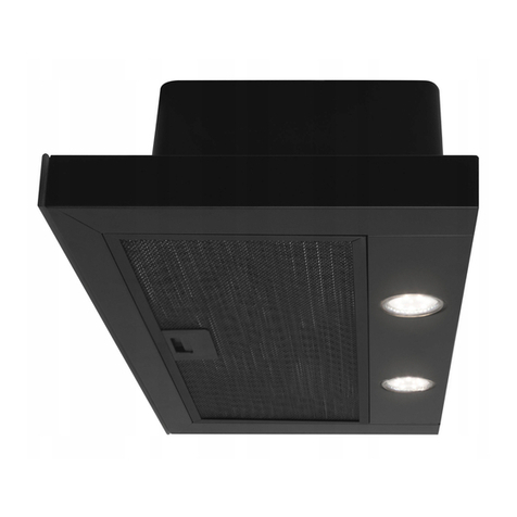
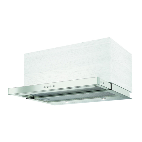
Meireles MEP 261 X User manual

1
Hood User Manual
3110-3112-3113-3115-3120-3122-3123-3130-3131-3140
3141-3143-3150-3151-3152-3153-3155-3157-3158-3160
3161-3170-3171-3173-3174-3175-3176-3210-3272-3321
3322-3324-3325-3326-3350-3351
Manual de Ut�l�zador
MEP 261 X
MEP 291 X
MEP 361 X
MEP 391 X
MEP 191 XN
MEP 470 XN
MEP 291 CR
MEP 291 R
MEP 291 BL
MEP 291 PB

2
DESENHOS TÉCNICOS
MEP 261 X - MEP 291 X - MEP 291 CR
MEP 291 R - MEP 291 BL - MEP 291 PB

3
WARNINGS AND SAFETY PRECAUTIONS
AVISOS E PRECAUÇÕES DE SEGURANÇA
* Este produto está destinado a uso doméstico.
* O seu produto usa voltagem de 220-240V/50Hz
* O fio terra é usado na ligação eléctrica do produto.
Este cabo deve ser definitivamente ligado a uma
tomada segura.
* Todas as ligações devem ser feitas por um técnico
qualificado.
* Uma instalação feita por pessoas não autorizadas
pode causar acidentes, danificar ou prejudicar a
performance do produto.
* Durante a montagem o cabo não deve estar sujeito
a esmagamento. Nem estar perto do fogão, pode
causar incêncio.
* Não coloque na tomada antes de o instalar.
* Deixe a tomada num local acessível, para que o
possa desligar quando necessário.
* Não toque nas lâmpadas podem estar quentes.
* Se usar o exaustor para uso não doméstico podem
ocorrer riscos e ficará fora da garantia.
* Siga as instruções para a saída de ar.
* Comidas flamejantes não devem ser usadas por
debaixo do exaustor.
* Ligue o produto depois de colocar a frigideira
na placa. Caso contrário, a alta temperatura pode
causar deformação no produto.
* Não deixe óleo na placa. As frigideiras com óleo
quente podem voltar a inflamar.
* Preste atenção às curtinas e tampas durante a
cozedura porque o óleo pode inflamar.
* Certifique-se que os filtros são mudados
convenientemente. Os filtros que não são mudados
podem incinerar porque contêm gorduras.
* Não coloque filtros que não estejam preparados
para o calor.
* Não opere o exaustor sem filtro de alumínio, não
remova os filtros quando está ligado.
* Em caso de chama, desligue o aparelho e os
aparelhos de cocção.
* O seu produto pode causar risco de incêndio se
não o limpar periodicamente.
* Desligue o produto antes de começar o processo
de manutenção (desligue na tomada).
* Quando a chaminé e os aparelhos de cocção usam
outra energia que não a eléctrica ao mesmo tempo,
a pressão negativa na sala não deve ser maior do
que 4 Pa (4x10 bar)
* Se houver outro aparelho a funcionar com
combustível no mesmo local que o exaustor,
este aparelho deve estar isolado do seu volume
totalmente e o aparelho deve ser do tipo hermético.
* Quando a conexão da chaminé for aplicada ao
seu produto, use condutas de 150mm ou 120mm
de diâmetro. Deve ser o mais curta possível e sem
curvas.
* Mantenha a embalagem longe de crianças pois
pode ser perigosa.
* Assegure-se que a criança não brinca com o
produto.
* Se o cabo eléctrico está danificado, deve mudá-
lo, por pessoal qualificado especialista para prevenir
alguma situação perigosa.
* Este aparelho não deve ser operado por
pessoas (incluindo crianças) com dificuldades
fisícas, sensoriais, ou mentais, a não ser que
supervisionadas por uma pessoa responsável.
* A distância entre o aparelho e a banca deve ser
maior do que 65cm em placas eléctricas e maior do
que 75cm em placas gás e noutro tipo de fogões.
* A exaustão do aparelho não deve estar conectada
com outras condutas com fumo.
* Deve ter cuidado quando o aparelho funciona
com outros aparelhos que usam o ar do espaço
(aquecedores, aquecedores de água a gás, fumo,
gasolina, ou madeira) porque podem afectar
negativamente o desempenho da exaustão.
* Este aviso não se aplica a aplicações sem fluídos.

4
Posição do aparelho
A distância entre o aparelho e o fogão não deve ser menor a 65cm se usar uma placa eléctrica e menor do
que 75cm se usar uma placa a gás. (Figura 1)
Figura 1
Instalação, retire o produto da embalagem:
* Verifique que não existe nenhuma deformação no produto.
* Danos no transporte deves ser imediatamente reportados ao transportador.
* Se notar algum dano reporte ao vendedor.
* Não deixe as crianças brincarem com o material de embalar!!!
Min : 65 cm
Max: 75 cm
Standard accessories Optional
accessories
INSTALLATION TEMPLATE
Acessórios standard Acessórios opcionais

5
ALERTAS DE SEGURANÇA
Risco vital, risco de envenenamento!
Há um risco vital de ser evenenado devido
a sucção de gases combustíveis. Não opere o
aparelho juntamente com aparelhos de circulação
de ar quente a não ser que tenho uma boa entrada
de ar garantida.
Aparelhos de circulação de ar quente (gás, gasolina,
madeira, carvão, etc) tomam a combustão de ar do
espaço e descargam o ar desperdiçado no sistema
de desperdício de gás. Com o exaustor a funcionar
o ar é retirado, criando um vacuo que o fornecimento
de ar não garante.
Risco de fogo!
Devido a chamas dispersas. O aparelho pode
ser instalado sob um aparelho de aquecimento
que use um combustível sólido (madeira ou carvão),
só se tiverem uma cobertura que não possa ser
removida.
Risco de choque!
Devido a um dano no cabo. Não dobre o
cabo durante a instalação.
Risco de lesão!
Há um risco de lesão nos cantos afiados do
produto durante a instalação. Use sempre
umas luvas de protecção para o instalar.
Risco de lesão!
Devido a deixar cair o aparelho. Use botas de
segurança.
Manutenção e Limpeza
Risco de queimadura, risco de choque!
Devido ao aparelho. Deixe o aparelho arrefecer
antes de limpar. Desconecte o cabo.
Cuidado!
. Há um risco de dano devido à entrada de humidade
nos componentes electrónicos. Não limpe os
elementos de controlo com um pano molhado.
. A superfície pode ficar danificada devido a indevida
limpeza. Limpe a superfície de aço inoxidável na
direcção do escovado. Não use produtos de limpeza
de aço nos comandos.
. A superfície pode ficar danificada devido ao uso de
abrasivos. Não use estes materiais.
Manutenção e reparação
Risco de incêndio!
Devido a reparação imprópria. Desconecte
o aparelho ou remova o cabo da tomada. As
reparações devem ser levadas a cabo por técnicos
especializados.
Risco de lesão!
Em caso de falha ou dano no aparelho. Desconecte
o aparelho ou remova o cabo da tomada, chame um
técnico.
Risco de incêndio!
Devido a um dano na conexão. Deve ser feita uma
substituição da conexão por um técnico.
Risco de queimadura!
Em caso de falha no bulbo, desconecte a conexão e
remova o cabo da tomada. Substitua o bulbo assim
que esteja fresco.

6
Operating modes
You may operate this appliance with discharge air
mode and circulated air mode.
Discharge air mode
Intake air is cleaned with oil filters and discharged
through a pipe system.
Note: Waste air shall not be discharged neither to
an active smoke or waste air flue nor to a flue used
for the ventilation of rooms where heating appliances
are installed.
■ If you want to discharge the waste air to a non-
active smoke or waste air flue, you shall take
permission from an authorized chimney sweep.
■ If the waste air is discharged through an outside
wall, a telescopic wall case shall be used.
Circulated air mode
Intake air is cleaned with oil filters and active carbon
filter and returned back to the kitchen.
Note: You shall install an active carbon filter to trap
particles that cause odor in the circulated air mode.
For various possibilities to operate the appliance in
circulated air mode, please refer to the manual or
consult your authorized dealer. You may buy the
accessories required for this procedure from relevant
sales points, authorized dealers or from the online
sales center. Refer to the end of operating manual
for part numbers of the accessories.
Cleaning and protective maintenance
■ Surface may be damaged due to abrasive or
hard cleaning materials. Never use abrasive or hard
cleaning materials. Cleaning of the appliance surface
Procure the proper cleaning and protective materials
for your appliance from the authorized service.
Note: Surface of the appliance and control units are
delicate against scratches.
■ Clean the surfaces with a soft, damp cloth, dish
soap or a less active glass cleaning material. Soften
the dirt that is dried and stuck on the surface with a
damp cloth. Do not rub!
■ It is not suitable to use dry clothes, scratchy
sponges, materials that require rubbing, cleaning
materials with sand, sodium carbonate, acids or
chlorine and other active agents.
■ Clean the stainless steel surfaces on the machining
direction only.
■ Do not use stainless steel cleaners and damp
clothes for control elements.
Cleaning metal oil filters
Metallic oil filters used in the appliance traps the oil
particles inside the humidity and vapour occurred
in the kitchen. Clean the metal oil filters every
three months approximately with a normal level of
operation (1 to 2 hours per day).
■ Do not use over-active cleaning materials with acid
or javel solution.
■ Clean the holding mechanisms of metal oil filters
with a damp cloth while cleaning the metal oil filters.
■ You may wash the metal oil filters with a
dishwasher or manually.
In the dishwasher:
Note: A light discoloration or change of color may
occur when the filters are washed in a dishwasher.
This does not affect the function of metal oil filter.
■ Do not wash heavily dirty metallic oil filters with
other dishes.
■ Place the metallic oil filters on a dishwasher loosely
or freely. Do not allow metal oil filters to be jammed.
Manual cleaning:
Note: You may use a special fat solvent for heavily
soiled filters. You may buy this solvent from the
online sales center.
■ Soften the metal oil filters in hot water with dish
soap.
■ Use a brush for cleaning and rinse the filters
thoroughly afterwards.
■ Metal yağ filtrelerdeki sıvıların iyice akmasını
bekleyiniz.

7
FILTROS DE CARBONO ACTIVO
Os filtros de carbono activo devem ser usados para
filtrar o ar da sala sem a necessidade de tubagem,
retornando o ar para a sala. Desligue o aparelho
antes de colocar os filtros. Os filtros devem ser
mudados de cada 3 a 5 meses de acordo com o
uso. Não lave os filtros de carbono. Os filtros a óleo
devem ser sempre instalados quer tenha filtros de
carbono ou não. Não use o aparelho sem o filtro de
óleo.Figura 1
Figura 1
Substituição dos Filtros
Pressione a pega superior para baixo e puxe na
sua direcção para remover o filtro. Figura 1a
Figura 1a
Instalar o Exaustor na Parede
Há duas barras apoiantes em forma de L, juntas
com parafusos para suspender o aparelho na
parede. Fixe as barras no corpo do produto com
parafusos M5X40 antes de suspendê-lo. Figura 2
Figura 2
Instale a saída de plástico no topo da cabine do
motor com parafusos 3,5 x 9,5. Figura 3
Figura 3
Furar os Buracos de Montagem
Anexe o esqueme de montagem na parede e fure
os buracos nos pontos marcados como A,B,C,
D com um berbequim 8mm. Figura 4 Coloque
tampões de 10mm nos buracos que furou.

8
Com referência ao min e max de altura do aparelho
perfure os buracos D e E usando um berbequim
6mm. Instale tampões de 6mm nos buracos que
furou.Figura 5
DE
Figura 4
Figura 5
AB
C
DE
Aperte os parafusos apoiantes
Fixe o produto à parede nos pontos A e B com os
parafusos 5,5X60. O espaço entre a cabeça do
parafuso e aparede deve ser de 5mm. Figura 6
Figura 6
DE
DE
Aparafuse a placa de instalação aos tampões de
6mm ue colocou nos pontos E e F com os parafusos
3,9x22. Figura 7
Coloque Exaustor na Parede
Pendure a barra apoiante em L nos pontos A e B
Figura 8
Figura 7
Figura 8
Figura 9
Aperte os parafusos apoiantes com o aparafusador
como na Fig.6 com o berbequim. Figura 9
Após fixar o aparelho completamente, fixe o corpo
à parede com o parafuso do corpo para prevenir
que o aparelho se mova. Figura 10
Figura 10

9
Nota: se o exaustor estiver aparafusado,
ajuste o alinhamento do mesmo ao
soltar ligeiramente os parafusos M5 que
suspendem a placa. Figura 11
Figura 11
Instalar o Tubo de Alumínio Flexível
Conecte o tubo de alumínio flexível à saída de ar no
produto e parede da cozinha.Figura 12
As curvas e cantos do tubo de alumínio podem
diminuir a passagem de ar.
Evite que ocorra. Figura 13
O aparelho pode ter só um tubo para diferentes
modelos.
Figura 12
Figura 13
Aparafuse o tubo interno pelos lados ao tubo de
instalação fixado à parede e fixe-o ao corpo por
dentro do tubo exterior. Figura 14
Figura 14

10
Operação
Fan level indicator
Fan On/Off Fan Level
Reduction
Fan Level
Increase
Timer Lam On/Offp
Ligar a Ventilação
Pressione no botão On/Off
Aumente no + e diminua no -
Ilumincação
Pode ligar ou desligar a iluminação.
Temporizador: Quando pressiona este botão
por mais de 2 segundos, a função é activada por 15
minutos, e o motor desliga automaticamente após
o período.
Fan kademesi göstergesi
Fan On/Off Fan Kademesi
Küçültmesi
Fan Kademesi
Büyültmesi
Timer Lamba On/Off
Comandos de 3 Velocidades
12345
1 - Pressione o botão para operar na velocidade 1
2 - Pressione o botão para operar na velocidade 2
3 - Demonstrador
4 - Pressione o botão para operar na velocidade 3
5 - Pressione o botão para ligar a luz
Períodos para Limpeza de Filtros
Os filtros devem ser lavados de cada 2 ou 3
semanas, ou quando o sinal C acciona. Após limpar
os filtros pressione o botão velocidade 1 por mais de
3 segundos com o aparelho desligado, para remover
o sinal C. O sinal E indica que o produto volta à
normalidade.
“ C ” sign shall be displayed after 60 hours
operation of the appliance.
This explanation applies to models with djt
switch.
Desconecte o exausto
Para substituir as lâmpadas de halogéneo
retire a cobertura da lâmpada. Rode no
sentido do relógio e puxe para baixo a lâmpada e
substitua. Figura 15
Figura 15
Substituição das Lâmpadas
Desligue a ligação do exaustor. Retire os filtros.
Retire a lâmpada fundida, e substitua pela nova.
(Espera que elas arrefeçam).
Substituição das Lâmpadas
Desligue a ligação do exaustor. Retire os filtros.
Retire a lâmpada fundida, e substitua pela nova.
(Espera que elas arrefeçam).
Para substituir as lâmpadas retire a cobertura da
lâmpada. Puxe para baixo a lâmpada e substitua.
Figura 16
Figura 16
Ventilação em modo de Boost intensivo
O modelo que comprou tem um modo de ventilação
.intensivo com o intuito de eciência energética
Modo Boost: símbolo de produto (b) vai aparecer no
.ecra quando a última velocidade estiver em uso
O símbolo b signica que a função boost (ventilação
.intensiva) está activa
O produto vai trabalhar por 6 minutos quando este
.modo e símbolo b estiverem a piscar
No nal dos 6 minutos o produto passa automati-
camente a uma velocidade inferior e permanecerá
.nessa
Nota: O temporizador não funciona com a função
.boost

11
Antes de contactar o serviço técnico
Assegure-se que o produto está ligado à tomada e
que os fusíveis estão a funcionar.
Se a Luz não funciona:
.Assegure-se que o aparelho está desconectado.
.Verifique os bulbos. Aperte-os ou substitua-os.
Possíveis falhas
A) Se o aparelho não funciona
- Verifique o fusível do aparelho se está conectado.
- Verifique se o aparelho está conectado.
B) Se a performance não corresponde ou faz
demasiado barulho:
- O diâmetro do tubo é o adequado? (mín 120mm)
- Os filtros estão limpos? Verifique.
- Assegure-se que os filtros de carbono não têm
mais de 6 meses.
- Assegure-se que a cozinha tem um bom sistema
de circulação de ar.
Se o aparelho não funciona:
Antes de contactar o serviço:
Assegure-se que o cabo e os fusíveis estão bem
instalados. Verifiue a tabela 1 antes de contactar o
serviço.
Substituição das Lâmpadas
Desligue a ligação do exaustor. Retire os filtros.
Retire a lâmpada fundida, e substitua pela nova.
(Espera que elas arrefeçam). Figura 17
Figura 17
Substituir o LED
Desconecte o aparelho.
*Remova a conexão da lâmpada LED
*Pressione a lâmpada com a mão para a remover.
* Remova o adesivo por volta da lâmpada.
*Antes de pôr a nova LED, remova a protecção da
moldura e cole-a no corpo do aparelho.
Table 1
ESPECIFICAÇÕES TÉCNICAS

12
Hood User Manual
3110-3112-3113-3115-3120-3122-3123-3130-3131-3140
3141-3143-3150-3151-3152-3153-3155-3157-3158-3160
3161-3170-3171-3173-3174-3175-3176-3210-3272-3321
3322-3324-3325-3326-3350-3351
Hood User Manual
MEP 261 X
MEP 291 X
MEP 361 X
MEP 391 X
MEP 191 XN
MEP 470 XN
MEP 291 CR
MEP 291 R
MEP 291 BL
MEP 291 PB

13
TECHNICAL DRAWINGS
MEP 261 X - MEP 291 X - MEP 291 CR
MEP 291 R - MEP 291 BL - MEP 291 PB

14
WARNINGS AND SAFETY PRECAUTIONS
*This appliance is intended for home usage.
*Operating voltage of your appliance is 220-240
Volt~50 Hz.
*A grounded plug is installed on the power cord of
your appliance. This cord shall always be plugged to
a grounded outlet.
*Electrical installation shall be performed by a
qualified electrician.
*Installation by unqualified persons may cause
operation with low performance, damage to the
appliance or accidents.
*Power cord shall not be crushed or smashed during
installation. Do not route the power cord near the
stoves; cord may melt and cause fire.
*Do not plug the appliance before installation of the
appliance.
*Make sure that the plug is easily reachable in order
to unplug the appliance in case of any danger.
*Do not touch the lamps of your appliance when they
have operated for a long time. Lamps may burn your
hand as they may be hot.
*Kitchen hoods are intended for home usage only
with normal cooking. There is a risk of fault and it
shall be void of warranty when it is operated for other
purposes.
*Comply with the regulations of the authorities on the
discharge of outlet air. (This warning does not apply
to flueless applications.)
*Do not cook flammable food under the appliance.
*Operate your appliance after putting a pan, pot etc.
on the stoves. Otherwise, high temperature may
cause deformation of some parts of appliance.
*Turn off the stove before removing a pan, pot etc.
from the stoves.
*Do not leave hot oil on a stove. Pots with hot oil
inside may catch fire by itself.
*Oil may catch fire while you are frying etc.; watch for
your curtains and linens.
*Ensure that the filters are replaced in time. Filters
that are not replaced in time may cause a risk of fire
due to the fat collected on them.
*Do not use filtering material that are not resistant to
flames instead of filters.
*Do not operate your appliance without filters; do not
remove the filters while the appliance is operated.
*In case of any fire, de-energize the hood and any
other cooking devices. (De-energize the appliance
by unplugging it.)
Your appliance may cause a risk of fire if the cleaning
is not performed as per the specified periods.
*De-energize the appliance before any maintenance
operations. (De-energize the appliance by
unplugging it.)
*Negative pressure inside the room when the electric
stove-top hood and other electrically powered
devices are operated simultaneously shall not
exceed 4 Pa ( 4 X 10 bar ).
*Any fuel- or gas-powered devices in the medium
where your appliance shall be used, such as room
heaters, shall be completely isolated from the volume
where the exhaust of this appliance is placed, or the
device shall be of hermetic type.
*Use pipes with a diameter of 150mm or 120 mm
when you use flue connection for your appliance.
Pipe connection shall be as short as possible and
have minimum number of elbows.
*Do not allow your children to play with the appliance.
Do not allow little children to use the appliance.
Use “MAX 6A” fuses on the hood installation for your
safety.
*Keep package material away from children as they
may pose a risk.
*If the power cord is damaged, it shall be replaced
by the manufacturer or its authorized service or by
an equally qualified technician to prevent any risky
condition.
*In case of any fire, de-energize the hood and any
other cooking devices, and cover the fire. Do not use
water to put off the fire.
*When the cooking appliances are being operated,
accessible parts may become hot.
*This appliance is not intended for use by persons
(including children) with reduced physical, sensory
or mental capabilities, or lack of experience and
knowledge, unless they have been given supervised
or instruction concerning use of the appliance by a
responsible person for their safety.
*The distance between the appliance and the stoves
should not be less than 65 cm in electric stoves and
not less than 75 cm in gas and other types of stoves
when the hood installation is completed.
*Exhaust of the hood shall not be connected to air
ducts with other smoke.
*You should be careful when the appliance is
operated with other appliances that use the air in
the room and their fuel (e.g. heaters, water heaters
that operate with gas, diesel fuel, coke or wood etc.)
Because, hood may negatively effect the burning of
the fuel as it exhausts the air inside the room.
*This warning does not apply to flueless applications.

15
APPLIANCE POSITION
The distance between the appliance and the stoves should not be less than 65 cm in electric stoves and not
less than 75 cm in gas and other types of stoves when the hood installation is completed. (Figure 1)
Figure 1
Installation Removing the Appliance from its Package:
* Check that your appliance is not deformed.
* Report the transport issues immediately to transport operator.
* Any faults encountered shall be reported to the dealer, too.
* Do not allow children to play with packing material!!!
Min : 65 cm
Max: 75 cm
Standard accessories Optional
accessories
INSTALLATION TEMPLATE

16
Vital risk, risk of poisoning!
There is a vital risk of being poisoned due to the
combustion gases sucked back. Do not operate
the appliance together with the air-circulated fire
appliances unless adequate air intake is ensured.
Air-circulated fire appliances (e.g. gas, oil, wood or
coal stoves, water heaters etc.) take the combustion
air from the installation place and discharge the
waste air with a waste gas system (e.g. flue). With
the hood being operated, air is taken from the kitchen
and neighbouring rooms. A vacuum is generated if
adequate air supply is not ensured. Poisonous gases
are sucked back from the flue and discharge gas
duct and re-entered to the house in such a condition.
■ Therefore, you shall always ensure that clean air
intake is always adequate.
Risk of fire!
Due to the sparks fluttering around. Appliance
is allowed to be installed over a heating
appliance operated with solid fuel (e.g. wood or
coal) only if there is a cover available that cannot
be removed. Current building codes and regulations
of the local power and gas companies shall be
considered for the installation work.
Risk of electric shock!
Due to damaged connection cable. Do not
kink or pinch the connection cable during
installation. .
Risk of injury!
There is a risk of injury due to the sharp edges
during installation work. Always use protective
gloves during installation work of the appliance.
Risk of injury!
Due to the dropping of the appliance. Always
fix all safety bolts and safety covers properly.
Cleaning and protective maintenance
Risk of being burnt, Risk of electric
shock!
Due to the appliance. Allow the appliance to cool
before any cleaning or maintenance. Disconnect the
fuse connection or remove the plug.
Caution!
■ There is a risk of damage due to the humidity
ingress in electronic components. Do not clean the
control elements with damp cloth.
■ Surface may be damaged due to improper
cleaning. Clean the stainless steel surfaces on the
brushing direction only. Do not use stainless steel
cleaners for control elements.
■ Surface may be damaged due to abrasive or
hard cleaning materials. Never use abrasive or hard
cleaning materials.
Maintenance and repair
Risk of fire, risk of injury! Due to improper or out of rule
repairs. Disconnect the fuse connection or remove
the plug. Repair work shall always be performed by
qualified personnel (electronic technicians).
Risk of injury!
In case of a fault or damage on the appliance,
disconnect the fuse and remove the plug and call the
authorized service.
Risk of fire, risk of injury!
Due to damaged connection cable. A damaged
connection cable shall always be replaced by
qualified personnel (electronic technicians).
Risk of being burnt, Risk of electric
shock!
In case of a faulty bulb, disconnect the fuse
connection or remove the plug. Replace the faulty
bulbs immediately to prevent overloading of other
bulbs (allow the bulbs to cool first).

17
Carbon Filter
Active carbon filters shall be used for filtering the
air inside the room and giving it back to the room
in environments without a flue connection. You may
procure the active carbon filter from your authorized
dealer or service. De-energize the appliance before
replacing the carbon filter. Carbon filter shall be
replaced every 3 to 5 months based on the frequency
of operation as it is used in kitchens without flue
outlet. Do not wash the carbon filter. Always have oil
filters installed on the appliance without respect to the
availability of the carbon filter. Do not operate your
appliance without oil filter. Replacement of carbon
filterThere are 2 carbon filters on the appliance.
Rotate the carbon filter clockwise to install it.
Figure 1
Figure 1
Replacement of Aluminum Cartridge
Carbon Filter
Press on the upper catch and pull towards yourself
to remove the carbon filter. Figure 1a
Figure 1a
Installation of the Appliance
Installation of the suspension plate to
the hood:
There are 2 (L) shaped suspension plates available in
the installation accessories to suspend the appliance
to the wall. These plates are supplied with a screw
set to provide ease of installation. Screw these plates
on M5 drive nuts on the cabinets with M5 x 40 screws
before suspending the appliance. Figure 2
Figure 2
Installation of the plastic flue to the
hood: Fix the plastic flue to the motor connection
plate with a 3.5x9.5 screw. Figure 3
Figure 3
Drilling of Suspension Holes
Fix the installation template to the surface where
the hood shall be suspended and drill holes in the
points marked with (A,B,C) using a Ø 8 mm drill bit.
Figure 4
Tap 10 mm plastic dowels to the holes you have
drilled.

18
Drill the D, E points with a Ø 6mm drill bit to screw
the flue installation plate referring to the min. and
max. heights of the appliance. Figure 5
Install 6 mm dowels to the holes you have drilled.
DE
Figure 4
Figure 5
AB
C
DE
Tightening the suspension screws:
Tighten 5.5x60 suspension screws to Ø10 mm
dowels (A, B) you have tapped on the wall. The
distance between screw head and the wall shall be
5 mm. Figure 6
Figure 6
DE
DE
Tighten the flue installation plate to the Ø 6 dowels
you have tapped to the wall using the 3.9x22 screw
supplied with your hood. Figure 7
Suspending the Hood to the Wall:
Hold the hood from its body and suspend it to the
wall on A and B points using the (L) plates you have
fixed on the hood cabinet before. Figure 8
Figure 7
Figure 8
Figure 9
When the suspension procedure is completed,
tighten the suspension screws installed to the wall in
Fig. 6 with a screwdriver to prevent moving of the
appliance. Figure 9
After you have fixed your hood completely, secure
the body with a screw from the hole (C) inside the
body to prevent it from moving.Figure 10
Figure 10

19
NOTE: If the hood seems skewed, adjust
the alignment of the hood by loosening
the M5 screws that the suspension
plates on the top are installed to.
Figure 11
Figure 11
Installation of aluminum pipe: Install the
flexible aluminum pipe to the plastic flue. Install the
other end of the pipe to the flue hole on the wall.
Figure 12
Avoid bends and elbows as much as possible
as the bends and elbows in the aluminum pipe
shall reduce the air suction power.
Engage the flues to the circumference of the body.
Figure 13
Appliance may have single flue on some model
options. In this case, you may procure the inner
flue suitable for your appliance from your authorized
dealer.
Figure 12
Figure 13
Tighten the inner flue to the flue installation plate
secured on the wall from its upper external sides.
Figure 14
Figure 14

20
Operation
This manual applies to several appliance variants.
Some specifications described here may not apply
to your appliance.
Note: Turn on the hood when you start cooking
and turn it off only after a few minutes later than you
have finished cooking. The vapor inside the kitchen
is removed most effectively in this way.
Fan level indicator
Fan On/Off Fan Level
Reduction
Fan Level
Increase
Timer Lam On/Offp
Control area Variant 1
Turning on the fan: Variant 1
Press the On/Off button.
Increase the fan level with button or reduce the
fan level with button.
Fan kademesi göstergesi
Fan On/Off Fan Kademesi
Küçültmesi
Fan Kademesi
Büyültmesi
Timer Lamba On/Off
Fan kademesi göstergesi
Fan On/Off Fan Kademesi
Küçültmesi
Fan Kademesi
Büyültmesi
Timer Lamba On/Off
Illumination
You may turn on or off the illumination irrespective
of the fan.
Timer: When you press this button for more
than 2 seconds, a timer function of 15 minutes
shall be activated, display shall signal when the
timing function has started and motor shall stop
automatically after 15 minutes.
Fan kademesi göstergesi
Fan On/Off Fan Kademesi
Küçültmesi
Fan Kademesi
Büyültmesi
Timer Lamba On/Off
Control area Variant 2
12345
1- Press this button to turn on the appliance.
2- Press this button to operate the appliance in 3rd
speed.
3- Press this button to operate the appliance in 3rd
speed.
4- Press this button to operate the appliance in 3rd
speed.
5- Press this button to turn on lamps of the
appliance.
This explanation applies to models with push
button switch.
Cleaning Periods for the Metal Filters:
Filters shall be cleaned every 2 to 3 weeks (as per
frequency of operation) or when the “C” signal is
shown on the display. After cleaning and installing
the filters, press ( ) button (when the appliance
is turned off) to remove signal “C” for more than 3
seconds. “E” shall be indicated on the display and
normal operation shall be resumed. If you want to
resume operation without removing the “C” signal,
active speed shall be displayed for 1 second when
you press the ( ) button and “ C ” signal shall
be displayed again and the motor shall resume
operation.
“ C ” sign shall be displayed after 60 hours
operation of the appliance.
This explanation applies to models with djt
switch.
Replacement of Halogen Lamps
Disconnect the hood from mains
To replace halogen bulbs, press down from the
rear side of the lamp socket and pull the lamp
downwards, then rotate it a little clockwise and
remove it downwards. Figure 15
Figure 15
BOOST INTENSIVE VENTILATION MODE
The model have been purchased has intensive venti-
.lation mode with the intent of energy efciency
Boost Mode: Product symbol (b) will be appearing on
. the screen when the latest speed is in use
The symbol b signies boost mode ( intensive venti-
.lation) is active
Product will be working along 6 minutes with this
.mode and the symbol b will blink during this time
At the end of 6 minutes product will be passing to
lower speed level automatically and will proceed
.working in this speed level
.Note: Timer feature is not used in boost mode
This manual suits for next models
9
Table of contents
Languages:
Other Meireles Ventilation Hood manuals
Popular Ventilation Hood manuals by other brands

ELICA
ELICA Interstellar Instruction on mounting and use
Galvamet
Galvamet SKID Installation, operating and maintenance instructions
ROBINHOOD
ROBINHOOD RWH3CH6SS Service manual

Omega
Omega ORU50PXL instruction manual

John Lewis
John Lewis JLHDA101 user guide
Sirius Satellite Radio
Sirius Satellite Radio SM927 installation instructions

