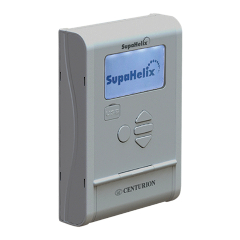
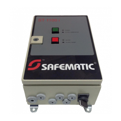
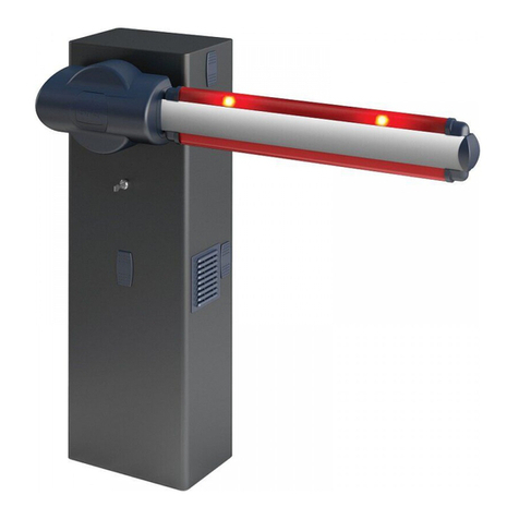
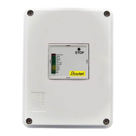
Meissner mts2000/02 User manual

Control system
Gate control mts2000/02
R2.8

I
meißner gate systems Gate control operating manual mts2000/02
Table of contents
1 Conformities
1.1 Guidelines and standards 1-1
1.2 CE mark 1-1
2 General safety information
2.1 Explanation of symbols used to provide safety information 2-1
2.1.1 Information regarding the safety information 2-1
2.2 Permissible users 2-2
2.3 Correct handling 2-2
3 Basic information
3.1 Warranty and liability 3-1
3.2 Purchaser obligation 3-1
3.3 User obligation 3-1
3.4 Correct use 3-1
3.5 Improper use 3-2
3.6 Instructions concerning EMC protection 3-2
4 Description of product
4.1 Safety concept 4-1
4.1.1 Safety equipment independent of the processor 4-1
4.1.2 Monitored safety equipment 4-1
4.2 Scope 4-2
4.2.1 Overview of operating modes 4-2
4.2.2 Interfaces for input elements 4-2
4.2.3 Interfaces for output elements 4-2
4.3 Structure 4-3
4.4 Operating modes 4-5
4.4.1 Impulse control as sequence control 4-5
4.4.2 Impulse control, defined up – down 4-5
4.4.3 Single/dual lane feedback control with light control
and automatic closing 4-6
4.4.4 Special operating modes 4-6
4.4.4.1 Manual mode 4-6
4.4.4.2 Emergency control 4-7
4.5 Functions 4-8
4.5.1 Continuously open switch ("gatekeeper’s switch")
/ external clock 4-8
4.5.2 Weekly indexing clock 4-8
4.5.3 Halt key 4-8
4.6 The safety equipment 4-9
4.6.1 Closing edge protection 4-9
4.6.2 Stop in open + closed position (protection against
anything being snagged and pulled in) 4-9
4.6.3 Stop in closed position (passage protection) 4-10
4.6.3.1 Process of re-opening after triggering
during closing 4-10

I
Gate control operating manual mts2000/02 meißner gate systems
Table of contents
4.6.3.2 Hold open time 4-10
4.6.3.3 Extending the hold open time 4-10
4.6.3.4 Shortening the hold open time 4-11
4.6.4 Run time monitoring 4-11
4.7. Technical data 4-12
4.7.1. Electrical data 4-12
4.7.1.1. Mains connection 4-12
4.7.1.2. Stop switch 4-12
4.7.1.3. Impulse sensor connections 4-12
4.7.1.4. Interfaces for safety equipment 4-12
4.7.1.5. Connection for potential-free contact 4-13
4.7.1.6. Connection for lights 4-13
4.7.1.7. Connection for drive 4-13
4.7.1.8. Device protection 4-13
4.7.2. Mechanical data 4-13
4.7.2.1. Ambient conditions 4-13
5 Assembly and installation
5.1 Safety information regarding assembly 5-1
5.2 Fitting gate control mts2000/02 5-2
5.3 Electrical connection 5-4
6 Start-up and operation
6.1 Programming gate control mts2000/02 6-1
6.1.1 Controls of gate control mts2000/02 6-1
6.1.1.1 Hardware settings 6-1
6.1.1.2 Function of keys 6-3
6.1.2 Menu structure of operating software 6-3
6.1.2.1 Language setting 6-3
6.1.3 Program gate 6-4
6.1.4 Service 6-7
6.1.5 Operation 6-8
6.2 Assembly instructions for weekly time switching clock
mts2000/02
(not in standard version) 6-9
6.2.1 Assembly 6-9
6.2.2 Programming 6-9
6.3 Operating instructions for radio mts2000/02
(not in standard version) 6-10
6.3.1 Assembly 6-10
6.3.2 Setting instructions 6-10
6.3.3 Coding table 6-11
6.3.4 Displays 6-11
7 Maintenance & service
7.1 Troubleshooting tool 7-1
7.1.1 Troubleshooting 7-1

I
meißner gate systems Gate control operating manual mts2000/02
Table of contents
7.1.1.1 Testing 7-1
7.1.2 Fault rectification 7-1
7.1.3 Control PCB measurement points 7-2
7.2 Regular testing 7-5
7.3 Address of manufacturer 7-6


1
meißner gate systems 1 - 1 Gate control operating manual mts2000/02
Conformities
1.1 Guidelines and standards
Device name:
Gate control mts2000/02
Guidelines and standards:
EMC 89/336/EEC: European guideline regulation on the electromagnetic
compatibility (EMC) of electrical equipment
VDE 0100: Guidelines for setting up high power systems of up to
1000V
VDE 0105: Operating high power systems
EN 60204: Electrical systems with electronics operating equipment
VDE 0160: Equipping high power systems and electric operating
equipment
VDE 0700: Safety of electrical devices for domestic consumption etc.
BGVA2: Electrical systems and operating equipment
BGR 232: Guidelines for power-assisted windows, doors and gates
Note The gate control system has been produced and inspected (TÜV Bau und
Betriebstechnik GmbH, corporate group for southern Germany in Filderstadt) in
accordance with the standards and guidelines listed and was in perfect condition
in terms of technical safety when leaving the factory.
1.2 CE mark
Gate control mts2000/02 corresponds to the fundamental requirements of the
relevant directive (EMC 89/336/EEC, dated 3 May 1989) of the Council of the
European Union.
Conformity has been proven and he corresponding documents (declaration) are
archived by the manufacturer.

2
Gate control operating manual mts2000/02 2 - 1 meißner gate systems
General safety information
2.1 Explanation of symbols used to provide safety
information
The following symbols are used in these instructions for use to provide the user
with safety information:
This symbol identifies a direct threat of danger to the health or even life of people.
Failure to follow these instructions can endanger life and limb, resulting in
anything from serious damage to health to life-threatening injuries.
This symbol identifies a risk of injury to the device user.
This symbol identifies important instructions on correct use of the device. Failure
to follow these instructions can result in malfunctions on the device.
Note This symbol identifies tips for application and particularly useful information which
will help you to make the most of all the device’s functions.
Liability exclusion:
This symbol indicates that operator error or failure on the part of the operator to
follow certain instructions can give rise to the manufacturer’s liability cover being
rendered null and void.
Instructions for disposal:
Ship used devices to an authorised recycling plant (separated into metals, plastics
etc.).
2.1.1 Information regarding the safety information
The safety instructions in these instructions for use MUST be noted and followed.

2
meißner gate systems 2 - 2 Gate control operating manual mts2000/02
General safety information
2.2 Permissible users
Only trained electricians may work on the electrical systems. They must assess
the work assigned to them, recognise any sources of possible risk and be able to
take appropriate safety measures.
2.3 Correct handling
In order to keep the device in perfect condition from a technical safety standpoint
and to be able to assure safe operation, the user undertakes to comply with the
points listed in this operating manual.
Operation of the control unit is only permitted while its covers and guards are all in
position. Ensure that all gaskets and screw connections are properly secured.

3
Gate control operating manual mts2000/02 3 - 1 meißner gate systems
Basic information
3.1 Warranty and liability
To be assured of success, warranty claims must be predicated on correct and
appropriate operation and handling. The manufacturer provides an assurance that
all parts are free of material and machining defects at the time of delivery.
Liability exclusion: The manufacturer assumes no liability for damage which is
caused by operating errors and/or failure to comply with the operating instructions
or a failure to carry out maintenance or servicing.
3.2 Purchaser obligation
The purchaser must ensure that users are trained in the operation and all safety-
related aspects of gate control mts2000/02. A report should be produced by all
training course attendees documenting the training they have received and this
report should be kept on file.
Liability exclusion: The manufacturer assumes no liability for damage resulting
from any failure by the purchaser to comply with the purchaser’s obligations.
The purchaser undertakes
•to only allow trained groups of people to work with the device.
The purchaser is also responsible for ensuring that
•the operating instructions for gate control mts2000/02 are available to the group
of users when working with the device.
3.3 User obligation
All users must confirm in writing to the purchaser that they have read and
understood the safety information and operating instructions.
If errors occur as a result of incorrect operations, the user will be deemed to have
been responsible.
3.4 Correct use
Gate control mts2000/02 is fitted in line with state-of-the-art technology and the
recognised rules governing safety with technical equipment.
Gate control mts2000/02 should only be used
•to activate gates which are driven using three-phase motors with reversal inhibit
protection and limit switches or AC / DC motors with limit switches
when in perfectly safe technical condition.
Correct usage also includes:
•observing all instructions in the operating instructions

3
meißner gate systems 3 - 2 Gate control operating manual mts2000/02
Basic information
3.5 Improper use
Incorrect or improper use of the device can put the life and limb of the user at risk,
inflict injury on the user and damage the device and/or other material assets.
Liability exclusion: The manufacturer assumes no liability for damage caused by
improper use.
3.6 Instructions concerning EMC protection
The controller has been manufactured and tested in accordance with the
corresponding guidelines for EMC (see Section 1.2 CE marking). However, it is
possible that mains voltage peaks (due to non-EMC compatible loads, for example)
may cause the processor to switch off.
This procedure is intentional and in no way affects the controller’s safety functions.
The processor restarts automatically thereafter and the controller is set to “Ready”
mode. The programme sequence can be restarted via the emission of a pulse.
These voltage peaks can be suppressed on-site (e.g. by inserting a mains filter as
close as possible to terminals 43 and 44, or by taking similar measures).

4
Gate control operating manual mts2000/02 4 - 1 meißner gate systems
Description of product
4.1 Safety concept
4.1.1 Safety equipment independent of the processor
All safety-related parts are incorporated in the safety chain (sensors and actuators)
directly and independently of the microprocessor.
The integrated microprocessor registers and reports from the results of the safety
monitoring process, but is not able to influence the safety measures triggered with
the exception of reversing the closing edge.
The possibility of uncontrolled gate movement triggered by the microprocessor is
therefore ruled out and is prohibited by the hardware.
4.1.2 Monitored safety equipment
The evaluation of all safety equipment corresponds to the standard set by the me-
chanical engineering industry:
1. Before every gate movement, the gate’s function is checked automatically.
2. If this function check produces an error, the system is shifted into error status
(red light(s) flash(es), if fitted).
3. The gate system cannot be started if an error is present. Normal operations
can only be continued once the cause of the error has been rectified.

4
meißner gate systems 4 - 2 Gate control operating manual mts2000/02
Description of product
4.2 Scope
Gate control mts2000/02 can be used wherever a high degree of flexibility and
complexity is needed. It is used to activate the gates, refer to Chapter 3.4 (Correct
use)
The operating modes are programmed via a removable display / keypad module.
4.2.1 Overview of operating modes
•Impulse control
•Single/dual lane feedback control with light control and automatic closing
•Manual mode (with safety functions)
•Emergency actuation (without safety functions)
For more information, refer to Chap.4.4 “Operating modes”
4.2.2 Interfaces for input elements
The following external input elements can be connected up, e.g. as impulse sen-
sors:
•one or two command radio with/without antenna (optional plug-in module)
•pushbuttons
•pull buttons
•key-operated keys
•continuously open switch ("gatekeeper’s switch")
4.2.3 Interfaces for output elements
The following external output elements can be connected up to the gate control:
•external lighting for stairways and garages, activation for ventilation
or
fault message (contact is open in the event of a fault or fall in voltage)
•lights

4
Gate control operating manual mts2000/02 4 - 3 meißner gate systems
Description of product
4.3 Structure
The gate control is housed in a robust industrial housing of safety class IP54 with
the dimensions 250 x 160 x 127 mm.
The function group consists of two PCBs:
•connection PCB
•control PCB
•removable display PCB with programming keys
Firstly, release plug from connection X1, then remove PCB and bolts
The operating and fault statuses appear on the LCD display on the control PCB.
Fig. 4 –1 Control PCB with controls

4
meißner gate systems 4 - 4 Gate control operating manual mts2000/02
Description of product
Supply lines are guided into the housing via screw connections. Apertures which
are not used must be sealed with blind plugs.

4
Gate control operating manual mts2000/02 4 - 5 meißner gate systems
Description of product
4.4 Operating modes
4.4.1 Impulse control as sequence control
Function: Opening and closing the gate system after activation taking the safety
equipment and if necessary the pre-warning time setting into consideration.
Details:
•impulse sequence
•internal + key
Activation from either:
•radio
triggers the following function: motion status of gate changes in the following se-
quence:
OPENSTOP CLOSEDSTOP
If the gate is in its upper or lower limit position, the STOP status is jumped.
4.4.2 Impulse control, defined up - down
Function:
1. Opening and closing the gate system after activation taking the safety equip-
ment and if necessary the pre-warning time set into consideration.
Details:
•impulse for open
•impulse for close
•internal + / - keys
Activation from either:
•radio 2 commands
triggers the following function: the gate opens or closes.

4
meißner gate systems 4 - 6 Gate control operating manual mts2000/02
Description of product
4.4.3 Single/dual lane feedback control with light control and automatic
closing
Function:
1. Opening the gate system after activation taking the safety equipment into con-
sideration.
2. Closing the gate system once the hold open time and if necessary the pre-
warning time has lapsed taking the safety equipment into consideration.
3. Light control depending on the occurrence of signals at the inputs for impulse
inside, impulse outside or two channel radio.
Details:
•impulse inside
•impulse outside
•internal + / - key
Activation from either:
•radio
triggers the following function: the gate opens.
The direction of travel is approved using lights depending on gate control activation
(triggering from inside or outside). In the event of alternating activation (triggering
from inside or outside) within the hold open time, the direction of travel is changed
over using the lights after a pre-warning time which may be set if necessary.
The gate shuts automatically once the “hold open” time and if necessary the pre-
warning time has lapsed.
Note If selected, the superordinate special operating mode of continuously open
(clock) is undertaken in preference to the single/dual lane feedback control with
light control.
4.4.4 Special operating modes:
4.4.4.1 Manual mode
Function:
Opening and closing the gate system taking the safety equipment into considera-
tion.
Details:
The gate opens or closes for as long as the internal + or – keys are pressed.
Note
This mode is used for start-up as well as other functions.

4
Gate control operating manual mts2000/02 4 - 7 meißner gate systems
Description of product
4.4.4.2 Emergency control
Function:
Opening and closing the gate system regardless of the control system’s operating
mode.
Details:
The gate opens or closes for as long as the emergency control switches connected
up externally or internally are pressed (refer to Fig. 4-1 Control PCB with controls).
These switches have a direct impact on the drive.
The safety equipment fitted is bridged.
Operations without the control PCB attached are possible using the external emer-
gency control switches.
For reasons associated with safety, the operator must be able to fully view the
gate when pressing the emergency control switch.
Care must be taken to ensure that emergency control does not cause damage to
the gate and/or does not put people at risk.
Note We would recommend using a key-operated switch as the external switch.

4
meißner gate systems 4 - 8 Gate control operating manual mts2000/02
Description of product
4.5 Functions
4.5.1 Continuously open switch ("gatekeeper’s switch") / external clock
Any locking switch can be fitted on site as the continuously open switch. The con-
tinuously open function takes priority over all other operating functions; i.e. “live”
processes are interrupted and the gate switches into continuously open mode.
4.5.2 Weekly indexing clock
Function:
Holding the gate open and closed at defined times of the day.
Details:
The weekly indexing clock (which can be retrofitted) controls up to 8 opening-
closing cycles per day of the week. The switching times of the week days can be
programmed individually or as a group.
If the gate is opened, the traffic is control by the light functions.
When the gate is closed, the single/dual lane feedback control system is operated
by:
•impulse inside
•impulse outside
•internal + key
Activation from either:
•radio
For more information, please note the operating instructions for the clock, refer to
Chapter 6.2
Note
If selected, the superordinate special operating mode of continuously open
(clock) is undertaken in preference to programming the weekly indexing clock.
4.5.3 Halt key
A key with a make and break contact can be fitted on-site. The halt function takes
preference over all other operating functions; i.e. “live” processes are interrupted.

4
Gate control operating manual mts2000/02 4 - 9 meißner gate systems
Description of product
4.6 The safety equipment
4.6.1 Closing edge protection
Function:
Opening and/or reversing the gate once the safety equipment has been activated
during the closing process.
Details:
When the main closing edge protection is triggered during the closing process, the
gate either opens to its limit position or reverses for 1 sec. and remains in this posi-
tion. When at 2 sec. before the lower limit position, only reversing is possible (pre-
set).
If the main closing edge is activated, the control system undertakes a total of 3
attempts to close before a fault is displayed.
The fault status is reported by rapid fault flashing of the lights, if connected up (also
refer to option for the re-opening process described in Chapter "Program gate"
6.1.3).
The following can be connected up:
•optical system OS12
•optical system OSE
•resistance strip R = 8.2 K
Note The function of the closing edge protection is checked before every gate move-
ment. Configuration is undertaken via jumper J1 on the control system PCB
4.6.2 Stop in open + closed position (protection against anything being
drawn in)
Function:
Stop after activation during opening and closing.
Details:
When triggered – regardless of the gate status – the gate system is shifted into
stop mode.
This fault status is reported by the lights fault flashing.
Connections are available for one system protecting from anything being drawn in
on both the inside and outside. For assembly arrangements, refer to Fig. 4-2
Note The function of this safety equipment is checked before every gate movement.
Precondition: use of one-way light barriers (separate transmitter and receiver). A
reflection light barrier can also be connected up but this does not comply with the
safety rulings!

4
meißner gate systems 4 - 10 Gate control operating manual mts2000/02
Description of product
4.6.3 Stop in closed position (passage protection)
4.6.3.1 Process of re-opening after triggering during closing.
During the closing process, the gate will open to its limit position if the passage
protection is triggered.
Note This applies to all operating modes.
4.6.3.2 Hold open time
If the function is set to “NO” for "Reset hold open time via passage protection“ (also
refer to option for "RESET O TIME VIA PP" in Chapter "Program gate" 6.1.4), the
time expires despite the passage protection being triggered.
Note This applies to the single lane and dual lane feedback control operating modes.
4.6.3.3 Extending the hold open time
The hold open time is restarted by triggering the passage protection before the hold
open time lapses after opening the gate and reaching the top limit position. The
hold open time can be set to anything between 1 and 600 seconds.
Note This applies to the single/dual lane feedback control operating modes.
Table of contents
