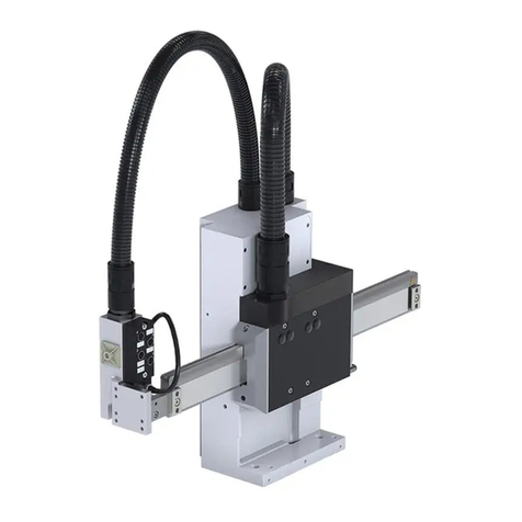
WEISS HP140T User manual

Installation- and operating manual
HP140T
Mechanical system documentation
980-204018000 / EN 09-2011
TD0037A-EN00-0000-00

Document: Installation- and operating manual
Document version: Mechanical system documentation
Valid for: Handling device
Type: HP140T
Revision R09-2011
This document has been prepared by
WEISS GmbH, Siemensstrasse 17, D-74722 Buchen
© Copyright
All rights in this document are the copyright of WEISS GmbH. This document may not be copied or reproduced,
in whole or in part, without the written permission of WEISS GmbH. This document is only intended for the user
of the product described and may not be passed on to third parties, in particular competitors.
Revisions
Date Revision Chapter Reason
15.08.2008 R08 - 2008 All Created
15.01.2010 R01 - 2010 1,2 Directive 2006/42/EC
15.09.2011 R09 - 2011 All Technical modifications

WEISS
Installation- and operating manual Handling device HP140T R09-2011 3/52
List of contents
1. Introduction ........................................................................................................... 5
1.1. Definition ....................................................................................................... 5
1.2. Correct use ................................................................................................... 5
1.3. Incorrect use ................................................................................................. 5
1.4. Laws / EC Directives / Norms ....................................................................... 5
1.5. EC Declaration .............................................................................................. 6
1.6. System-dependant documentation ............................................................... 6
1.7. Operating manual ......................................................................................... 7
1.8. Guarantee and liability .................................................................................. 8
2. Safety ..................................................................................................................... 9
2.1. Fundamental safety instructions ................................................................... 9
2.2. Safety equipment for the machine .............................................................. 10
2.3. Residual hazards ........................................................................................ 11
3. Product description ............................................................................................ 13
3.1. Structure ..................................................................................................... 13
3.2. Function ...................................................................................................... 14
3.3. Technical data ............................................................................................. 14
3.4. Electrical connections ................................................................................. 22
3.5. Option with automatic lubrication ................................................................ 24
3.6. Option with integrated pneumatic valves .................................................... 25
3.7. Option with tool connector .......................................................................... 26
4. Transportation ..................................................................................................... 27
4.1. Transportation damage ............................................................................... 27
4.2. Intermediate storage ................................................................................... 27
5. Installation ........................................................................................................... 28
5.1. Safety during installation ............................................................................. 28
5.2. Installation prerequisites ............................................................................. 28
5.3. Assembling the Pick & Place ...................................................................... 29
5.4. Assembly suggestions ................................................................................ 30
5.5. Weiss Tool-Connector ................................................................................ 33
5.6. Installing the safety equipment ................................................................... 34
5.7. Instructions on disposal of packaging material ........................................... 34
6. Commissioning ................................................................................................... 35
6.1. Safety during commissioning ...................................................................... 35
6.2. Initial commissioning ................................................................................... 36
6.3. Recommissioning ........................................................................................ 36
7. Operation ............................................................................................................. 37
7.1. Safety during operation ............................................................................... 37
7.2. Operating the Pick & Place ......................................................................... 37
7.3. Operating personnel workstations .............................................................. 37
8. Malfunctions ........................................................................................................ 38
8.1. Safety when remedying malfunctions ......................................................... 38
8.2. Errors / Cause / Remedy ............................................................................ 38
8.3. Customer Service ....................................................................................... 38
9. Maintenance ........................................................................................................ 39
9.1. Safety during maintenance ......................................................................... 39
9.2. Maintenance work ....................................................................................... 40
9.3. Inspections .................................................................................................. 40
9.4. Maintenance ............................................................................................... 41
9.5. Repair ......................................................................................................... 42
10. Decommissioning / Dismantling / Disposal ...................................................... 43
10.1. Safety during decommissioning and dismantling ........................................ 43
10.2. Decommissioning ........................................................................................ 43
10.3. Dismantling and disposal ............................................................................ 43
1
2

Installation- and operating manual Handling device HP140T R09-2011
4/52
WEISS
11. Service and spare parts ...................................................................................... 45
11.1. Ordering spare parts ................................................................................... 45
11.2. Spare parts list ............................................................................................ 45
12. Appendix .............................................................................................................. 46
12.1. Index ........................................................................................................... 46
12.2. Personal notes ............................................................................................ 48
Illustration indexGeneral view of the Pick & Place .................................................................................. 13
Example of a type plate ................................................................................................. 14
Axle loads ...................................................................................................................... 15
Installation positions ...................................................................................................... 15
Dimensions .................................................................................................................... 17
Screw hole pattern ........................................................................................................ 18
Adaption gripper ............................................................................................................ 19
Plug-in connections ....................................................................................................... 20
Terminals ....................................................................................................................... 20
Connections for automatic lubrication ........................................................................... 22
Pneumatic valve ............................................................................................................ 23
Tool connector ............................................................................................................... 24
Protective cover on the horizontal axle ......................................................................... 27
Adjustment via long holes ............................................................................................. 29
Firm pinning ...................................................................................................................30
Assembly at a groove .................................................................................................... 31
Gripper front side ........................................................................................................... 32
Gripper left ..................................................................................................................... 32
Gripper right ..................................................................................................................33
Lubricating spring .......................................................................................................... 42
Lubricating axles ........................................................................................................... 43
1
2

WEISS
Installation- and operating manual Handling device HP140T R09-2011 5/52
Introduction
1.1 Definition
1
1Introduction
1.1 Definition
Mechanical system documentation
Handling device HP140T
The Pick & Place is a handling device with direct motor-driven axles.
In the following, the Pick & Place will be referred to as "machine".
1.2 Correct use
The machine is a noncomplete machine conforming to Directive 2006/42/EC,
Article1gand2g.
The machine is designed for integration in other machines, in other incomplete machines
or equipment or for connection to these.
It may only be used within the limitations defined in the order characteristics.
Commissioning is forbidden until the conformity of the product in which the machine is
installed with Directive 2006/42/EC and all other Directives governing use has been
determined and confirmed.
Observance of the accompanying documentation and adherence to maintenance
regulations are also component parts of correct use.
1.3 Incorrect use
Any use of the machine above or beyond the directions for correct use is regarded as
incorrect and prohibited.
The machine must not be subjected to loads that exceed the maximum limits.
The machine is not suitable for use
•in wet or damp environments of any kind (water, oils, acids, steam or vapours, etc.).
•in an environment with gases or radiation.
•in potentially-explosive atmospheres.
•in environments which contain swarf.
1.4 Laws / EC Directives / Norms
The machine is designed and constructed to conform to
•applicable laws
•Directive 2006/42/EC (Machinery Directive)
•Low Voltage Directive, 2006/95/EC
•EMC Directive 2004/108/EC
•and the harmonised standards that we have cited
and meets state-of-the-art technological standards in terms of its construction.

Installation- and operating manual Handling device HP140T R09-2011
6/52
WEISS
Introduction
1.5 EC Declaration
1
1.5 EC Declaration
An EC Declaration as specified by Directive 2006/42/EC (Machinery Directive) is
included with each machine at delivery.
The text of this EC Declaration is as follows:
WEISS GmbH
Siemensstrasse 17
D-74722 Buchen, Germany
Declaration of incorporation of partly completed machinery
in accordance with EC Machinery Directive 2006/42/EC, Annex II B
Prohibition of commissioning
We hereby declare that the machine called Handling device HP140T is intended for the
installation into another machine or is to be assembled with other machines to a machine
in terms of the directive 2006/42/EC.
Commissioning is prohibited until it has been established that the machine into which the
aforementioned product should be installed satisfies the provisions of the EC Machinery
Directive, and that a Declaration of Conformity in accordance with EC Machinery Direc-
tive 2006/42/EC, Annex II A has been issued.
1.6 System-dependant documentation
In addition to this manual, further documents are required to ensure safe operation of this
machine. The specifications stated in these documents are to be observed.
For control system by WEISS-GmbH:
•Electrical operating manual
•WAS.handling Windows program operating manual
WAS.indexer Profibus DP
WAS.indexer CAN
WAS.indexer Ethernet
WAS.indexer RS232
AsIMA
DeviceNet
•Operating manual Hand-held grease gun (for the model with lubricating nipples)
•Operating manual automatic lubrication pump (for model with automatic lubrication)

WEISS
Installation- and operating manual Handling device HP140T R09-2011 7/52
Introduction
1.7 Operating manual
1
1.7 Operating manual
This operating manual is a translation of the original operating manual and is part
of the scope of delivery.
We reserve the right to undertake modifications resulting from further technological
development which diverge from the data and illustrations contained in this operating
manual.
The operating manual and the associated valid documentation are not subject to an auto-
matic revision service.
Information on the respective current edition can be obtained from the manufacturer.
Local regulations must be heeded.
This operating manual describes handling of the machine and contains important instruc-
tions and information to assist you in correct use of the machine.
The operating manual is designed for trained technical personnel and instructed persons.
It should be kept at the location of use of the machine at all times and read, understood
and applied by all persons entrusted with work on or with the machine.
Safety instructions in individual chapters should be observed.
1.7.1 Explanation of safety instructions in this manual
This manual contains instructions which you should observe for your personal safety and
to avoid material damage.
Safety instructions for yourpersonal safety are highlighted by a sign containing a warning
triangle and signal word. The associated text describes the hazard involved, avoidance
options and the consequences of a failure to heed the safety instruction.
General instructions or instructions relating to possible material damage are highlighted
by a sign without a warning triangle.
They are, depending on the degree of risk involved, illustrated as follows:
A warning triangle with the signal word DANGER
indicates an immediate hazardous situation which, if
not avoided, will lead to fatalities or grievous injuries.
A warning triangle with the signal word WARNING
indicates an potential hazardous situation which, if
not avoided, can lead to fatalities or grievous injuries.
A warning triangle with the signal word CAUTION
indicates an potential hazardous situation which, if
not avoided, can lead to light or medium injuries.
A sign with the signal word NOTICE indicates
potential material damage or provides additional
information which should be observed when
operating the machine.

Installation- and operating manual Handling device HP140T R09-2011
8/52
WEISS
Introduction
1.8 Guarantee and liability
1
1.7.2 Legend
In these manual images, symbols and abbreviations with the following meaning are used
for clarity:
1. Marks a numbered list.
a) Marks the second level of a numbered list.
•Marks a list.
Marks the second level of a list.
The book symbol before a section of text indicates additional applicable docu-
ments.
The information symbol before a section of text marks an additional note or an
important tip for use.
1.7.3 Figures
The figures used are examples. There may be differences between the illustrations and
the actual delivery.
1.7.4 Index of valid pages
Pages of this operating manual including the title page: 52
1.8 Guarantee and liability
The machine is covered by a guarantee of 24 months without shift limitations.

WEISS
Installation- and operating manual Handling device HP140T R09-2011 9/52
Safety
2.1 Fundamental safety instructions
2
2 Safety
2.1 Fundamental safety instructions
2.1.1 Operator‘s obligation to exercise diligence
This machine conforms to state-of-the-art technological standards and ensures a maxi-
mum level of safety.
However, this level of safety can only be attained under operating conditions if all measu-
res necessary for this have been taken. The operator‘s obligation to exercise diligence
includes planning of these measures and the inspection of their realisation.
The operator must ensure that
•the machine is only used as intended.
•the machine is only operated in faultless, functional condition and mechanical and
electrical safety devices are present.
•required personal protective clothing is provided for and used by operating, mainte-
nance and repair personnel.
•the operating manual and all other applicable documentation is maintained at all times
in legible condition and is accessible at the implementation site of the machine.
Ensure that all personnel who must execute activities tasks on the machine can
access the operating manual at all times.
•only adequately qualified and authorised personnel maintain and repair the machine.
•such personnel are instructed regularly in all questions concerning occupational
safety and environmental protection, including the operating manual and safety
instructions contained therein.
•all safety instructions and warnings affixed to the product are not removed and must
remain legible.
•national accident prevention guidelines and company-internal guidelines are complied
with.
•VDE regulations are complied with.
•the EMC legislation is complied with during installation.

Installation- and operating manual Handling device HP140T R09-2011
10/52
WEISS
Safety
2.2 Safety equipment for the machine
2
2.1.2 Requirements to be met by personnel
It is imperative that the following safety instructions be observed during all operations
involving the machine. This ensures avoidance of life-threatening injuries, machine
damage, other material damage and environmental damage.
Personnel must ensure that
•trainees are initially permitted to only work on the machine under the supervision of an
experienced person.
•all personnel who maintain the machine read the operating manual and confirm with
their signature that they have understood the operating manual.
•unauthorised persons are not in the vicinity of the machine when tasks are being per-
formed.
•supplemental to the operating manual the operating instructions as specified in labour
protection legislation and work equipment use legislation are complied with.
•the operator or supervisory personnel are informed in the event of malfunction.
•required personal protective clothing is used.
The following work described in this operating manual should only be realised by quali-
fied personnel:
•Installation
•Commissioning
•Operating
•Maintenance
2.2 Safety equipment for the machine
There are danger signs attached to the machine. Danger signs provide information about
possible hazards, which could be caused by the machine.
Danger sign Meaning
Beware of magnetic field
ASR A1.3 Annex 1; DIN 4844-2: 2001-02 and DIN 4844-2/A1:2004-05;
92/58/EEC directive regarding safety signs
Beware of hot surface
ASR A1.3 Annex 1; DIN 4844-2: 2001-02 and DIN 4844-2/A1:2004-05

WEISS
Installation- and operating manual Handling device HP140T R09-2011 11/52
Safety
2.3 Residual hazards
2
The operator is responsible for ensuring that a suitable safety concept is developed and
applied for the safe operation of the machine.
The operator must take all measures to protect his personnel against injury by the
machine.
These include:
•Safety housing with monitored safety door
•Emergency stop circuit
•Light barriers or switch mats
•Warning indicators
•Attach danger sign at the access point of the entire machine
We also recommend that the danger signs shown in chapter 2.2 are attached in an
enlarged form at the access points to the protection area of the entire machine.
2.3 Residual hazards
2.3.1 General residual hazards
Danger sign Meaning
Prohibited for persons with pacemakers
ASR A1.3 Annex 1; DIN 4844-2:2001-02 and DIN 4844-2/A1:2004-05;
ISO/FDIS 7010: 2003; ISO 7010
Strong magnetic fields
The axles give rise to strong magnetic fields. They can lead tofailure of medical implants
such as pacemakers and may result in severe or fatal injury. Persons with medical
implants such as pacemakers must maintain a safety distance of at least 50 cm from the
axles.
Objects made of magnetisable materials such as jewellery, watches or tools can be
attracted. Do not wear any magnetisable materials when handling the machine. Handle
tools carefully. Injuries caused by being pulled in.
Missing safety equipment
Operation without safety equipment is dangerous. The realisation of a suitable The
operator is responsible for the safety concept. The operator must provide for sufficient
safety measures such as protective grating, light grids, emergency stop button, covers,
warning notices, etc. Operation without safety equipment is prohibited. Injuries caused by
squeezing, impact, magnetism.
Missing danger signs
Damaged or illegible danger signs no longer fulfil their purpose. Make sure the danger
signs are complete and legible. Replace damaged danger signs.
Risk of explosion during operation in a potentially-explosive environment.
Due to constraints governing the correct used of the machine, the machine is not desi-
gned for use in a potentially-explosive atmospheres. The operator must take all
measures to ensure that the machine is only operated in a correct manner.
Use of spare parts / attachment of supplemental devices
If spare parts are used, or if supplemental devices are attached that are not approved by
the manufacturer, consequential damages can occur. Only use spare parts that are cited
inoursparepartslistor sparepartsthatwehaveapproved.You mustconsult withus prior
to attaching supplemental devices. Failure to comply with these instructions means that
the possibility of personal injury cannot be excluded.
Danger of crushing injuries due to impermissible changes
Injuries can occur as a consequence of impermissible changes. Do not make any
changes to the machine. Failure to comply with these instructions means that the possi-
bility of personal injury cannot be excluded.

Installation- and operating manual Handling device HP140T R09-2011
12/52
WEISS
Safety
2.3 Residual hazards
2
Electric shock
Power and control connections may still conduct electricity after the machine has been
deactivated and is stationary. Energised capacitors inside the servo amplifier may still be
charged, despite the power supply being deactivated. Work on electrical equipment
should only be realised by skilled electrical personnel and under observance of specifica-
tions in the electrical operating manual. Electrical connections for the machine should
onlybeloosenedorpluggedinwhenthepower supplyis deactivatedandsecuredagainst
reactivation. The status of capacitor charging should be measured prior to working on
machine electrical equipment. The procedure for measuring charges is described in the
electrical operating manual. Touching energised components can lead to serious or even
fatal injuries.
Squeezing or pulling in
The axles of the machine move very rapidly. Reaching into areas where parts are moving
may result in the crushing of limbs. Hence, never reach into the working area of the axles.
Injuries due to the moving axles are to be avoided by using appropriate safety devices.
Von den Permanentmagneten auf der horizontalen Laufschiene gehen starke magneti-
sche Kräfte bis zu einem Abstand von 15 mm aus. Personen, die magnetische Gegen-
stände wie herabhängenden Schmuck oder Uhren tragen, können angezogen und
verletzt werden.
Risk of injuries through burning.
The temperature of the housing and the axles can reach up to 80 °C during operation.
Prior to carrying out any work on these components, the machine must first cool down
sufficiently, to avoid any risk of burning through contact. Burn injuries will arise from
contact with hot components.
Hazards arising from machine damage
If the horizontal axle makes contact with magnetic objects, then this will destroy the
magnetic measuring system. The protective cover of the horizontal axle may first be
removed shortly before start-up.

WEISS
Installation- and operating manual Handling device HP140T R09-2011 13/52
Product description
3.1 Structure
3
3 Product description
3.1 Structure
The freely programmable Pick & Place HP140T integrates two perpendicular linear axles
- the horizontal axle [Y] and the vertical axle [Z] - in a compact housing.
All connections are guided through the rear.
The operator can add grippers or another device to the horizontal axle [Y].
A magnetic length-measuring system is employed.
The following parameters for the Pick & Place are variables:
•design of lubrication connections
•maximum horizontal and vertical stroke
•number of integrated pneumatic valves
•Adaption grippers
•Measuring system
Fig. 1: General view of the Pick & Place
YZ
i i i i i i i i i i i i i i i i i

Installation- and operating manual Handling device HP140T R09-2011
14/52
WEISS
Product description
3.2 Function
3
3.2 Function
The linear motors of the two axles are controlled via amplifiers. High positional accuracy
and repeat accuracy is achieved by the integrated magnetic measuring system.
The positional accuracy describes the acceptable tolerance of the linear unit for an ope-
rating command involving movement to a specified position. It is determined by mechani-
cal tolerances and the accuracy of the measurement system. Furthermore, the positional
accuracy is influenced by external and internal temperature changes. The specified posi-
tional accuracy is attained for temperatures within a range of +/-15°C.
The repeat accuracy describes the acceptable tolerance of the linear unit for the repea-
ted approach to the same position, including repeated activation and deactivation. It is
influenced by external and internal temperature changes as well as by the mechanical
stop conditions for the referencing. The specified repeat accuracy is attained for a con-
stant temperature (+/-10°C) only and without any external loads.
3.3 Technical data
3.3.1 Scope of delivery
The scope of delivery of the machine depends on the order involved. Please refer to the
ordering information or order characteristics for individual components.
3.3.2 Sound level
The A-weighted emission sound pressure level do not exeed the allowable peak.
3.3.3 Ambient conditions and weight
Humidity 5 % to 95 %, non-condensing
Allowable temperature range Storage: +5 °C to +55 °C
Operation: +15 °C to +45 °C
Environment The HP140T must not be operated in environments
that contain abrasive dust
Protection class IP20
Weight HP140 T with vertical stroke 65 mm: ca. 13 kg
HP140T with vertical stroke 100 mm: ca. 16 kg
i i i i i i i i i i i i i i i i i

WEISS
Installation- and operating manual Handling device HP140T R09-2011 15/52
Product description
3.3 Technical data
3
3.3.4 Type plate
The type plate is fitted to the housing of the machine and contains the details described
in the illustration.The illustrated type plate is merely an example of any machine and
is not identical to the actual type plate of the described product.
A second type plate is included in the scope of delivery. This second plate can be moun-
ted at a clearly-visible location on the machine to allow viewing of performance data if the
type plate fitted by the manufacturer is concealed by any other structures.
Fig. 2: Example of a type plate
Additional barcode serial number Version
Type (see table)
Serial Number
Vertical stroke
Horizontal stroke
Measurement system*
Year of construction
Weight
* sinus / cosinus measurement system with pole pitch of 1 mm
Type Encoder Description
HP140T-BB sin/cos 1 Vpp Encoders incremental with interface SIN/COS
HP140T-CB TTL Encoders incremental in customized special design
HP140T-DB SSI sin/cos Encoders absolute with interface SSI and interface
SIN/COS
HP140T-EB BISS Encoders absolute with interface BISS-C
Special types:
HP140T-BB-CL6 Clean room certificated type
HP140T-xC Type with special isolated temperature indicator for
Siemens-controller
HP140T-BB-R Type with Hall-Sensor for Rockwell-Controller
type
horiz.
serial
weight
vertical
encoder
year
HPXXXXT - XX
XXXX
XX mm
HPXXXXXX
sin / cos, 1
XX kg
XX mm
www.weiss-gmbh.de
HPXXXT X
X
WEISS
i i i i i i i i i i i i i i i i i

Installation- and operating manual Handling device HP140T R09-2011
16/52
WEISS
Product description
3.3 Technical data
3
3.3.5 Axles
3.3.6 Loads
The specified forces must not be exceeded, especially for picking up and setting down.
Fig. 3: Axle loads
3.3.7 Installation positions
Permissible installation positions for the machine are:
•Standing, horizontal axle horizontal, vertical axle vertical with a maximum incline of
25°.
Fig. 4: Installation positions
Type (Z-Axle) (Y-Axle)
Traverse paths Max. 65 / 100 mm Max. 160 / 270 / 300 / 400 mm
Acceleration Max. 40 m/s2Max. 40 m/s2
Speed Max. 2.0 m/s Max. 4.0 m/s
System accuracy 10 m/m incremental (sin/cos 1 Vss)
5 m/m absolut (BISS/C,SSI) optional
Repeat accuracy 5 m incremental (sin/cos 1 Vss)
2 m absolut (BISS/C,SSI) optional
Handling weight Maximum of 3 kg for gripper and work piece
Fy= 240 N Mk= 49 Nm Fz= 360 N MD= 15 Nm M = 36 Nm
Q
90° 90° ±25°
i i i i i i i i i i i i i i i i i

WEISS
Installation- and operating manual Handling device HP140T R09-2011 17/52
Product description
3.3 Technical data
3
3.3.8 Linear motors
3.3.9 Measurement system
3.3.9.1 Incremental (HP140TBx)
ID - B&R Description Unit Horizontal motor Vertical motor
Electrical Cycle Length [mm] 27,6 28,1
48 Nominal Voltage (DC) [VDC] 560 560
49 Back-EMF Constant (RMS) [V/(m/s)] 52 49
50 Nominal Speed [m/s] 3 3
51 Maximum Speed [m/s] 4 4
52 Stall Force [N] 65 130
53 Nominal Force [N] 65 130
54 Maximum Force [N] 240 360
55 Force Constant [N/A] 70 70
56 Stall Current [A] 1,2 2,4
57 Nominal Current [A] 1,2 2,4
58 Maximum Current [A] 3,5 5,8
59 Cross Section Area [mm20,088 0,196
60 Stator Resistance [Ohm) 33 13
61 Stator Inductance [Henry] 0,092 0,094
62 Actuator Mass [kg) 2,2 5,4
Thermostat PTC-Switch
< 250 Ohm at 20 °C / > 1000 Ohm at120 °C
Type EHP 1/90
Voltage supply +5 V ±5%, 35 mA
Incremental signals sin / cos 1 Vss
Signal period 1 mm
Resolution 0,244 µm (bei 4096times-Interpolation)
Accuracy measuring system 10 µm (transmitter + tape measure) at 20 °C
Referencs marks on request
Allowable temperature range Storage: -30 °C bis +80 °C
Operation: +10 °C bis +60 °C
Protection class IP 67
i i i i i i i i i i i i i i i i i

Installation- and operating manual Handling device HP140T R09-2011
18/52
WEISS
Product description
3.3 Technical data
3
3.3.9.2 Absolut (HP140TDx / HP140TEx)
3.3.10 Referencing by incremental encoder
The reference motion involves moving towards one fixed stop of the respective axle.
Type AHP 1/90
Voltage supply +5 V
Interfaces absolut BISS-C / SSI
Incremental signals sin / cos 1 Vss
Accuracy measuring system 5 µm (transmitter + tape measure) at 20 °C
Allowable temperature range Storage: -30 °C bis +80 °C
Operation: +10 °C bis +60 °C
Protection class IP 67
Data interfaces
Data length single turn 19 bits
Advanved zeros 0
Subsequent zeros 0
Data length multi turn no data output
Encoding binary
Fault bits none
Standardisation 1024/mm
Time -Out (Mono flop time)
Siemens: SSI: 16 µs
Bosch-Rexroth: SSI: 8 µs
BISS-C: 1 µs
The encoder may be read every X µs only
Work cycle Siemens: 100 kHz
Bosch-Rexroth: 500 kHz
BISS-C: < 1 MHz
i i i i i i i i i i i i i i i i i

WEISS
Installation- and operating manual Handling device HP140T R09-2011 19/52
Product description
3.3 Technical data
3
3.3.11 Dimensions
Fig. 5: Dimensions
1stroke vertical 100 mm
2stroke horizontal 160 mm
min. 15 - max. 287
min. 56 - max. 122
i i i i i i i i i i i i i i i i i

Installation- and operating manual Handling device HP140T R09-2011
20/52
WEISS
Product description
3.3 Technical data
3
3.3.12 Hole patterns
3.3.12.1Screw hole pattern
Fig. 6: Screw hole pattern
2stroke horizontal 160 mm
1 Side view base plate
2 Basic housing, HP140T
a Pin holes 6H7
b Long holes for M8 bolts
3 Hole pattern for customer base plate
120 ± 0,01
Ø 6H7
77
7,25
154,5
10 ± 0,05
75 ± 0,01
10P9
8,5 8,5
22
55,5
3
3
2
1
3
a
b
ab
a
i i i i i i i i i i i i i i i i i
This manual suits for next models
7
Table of contents
Other WEISS Control System manuals