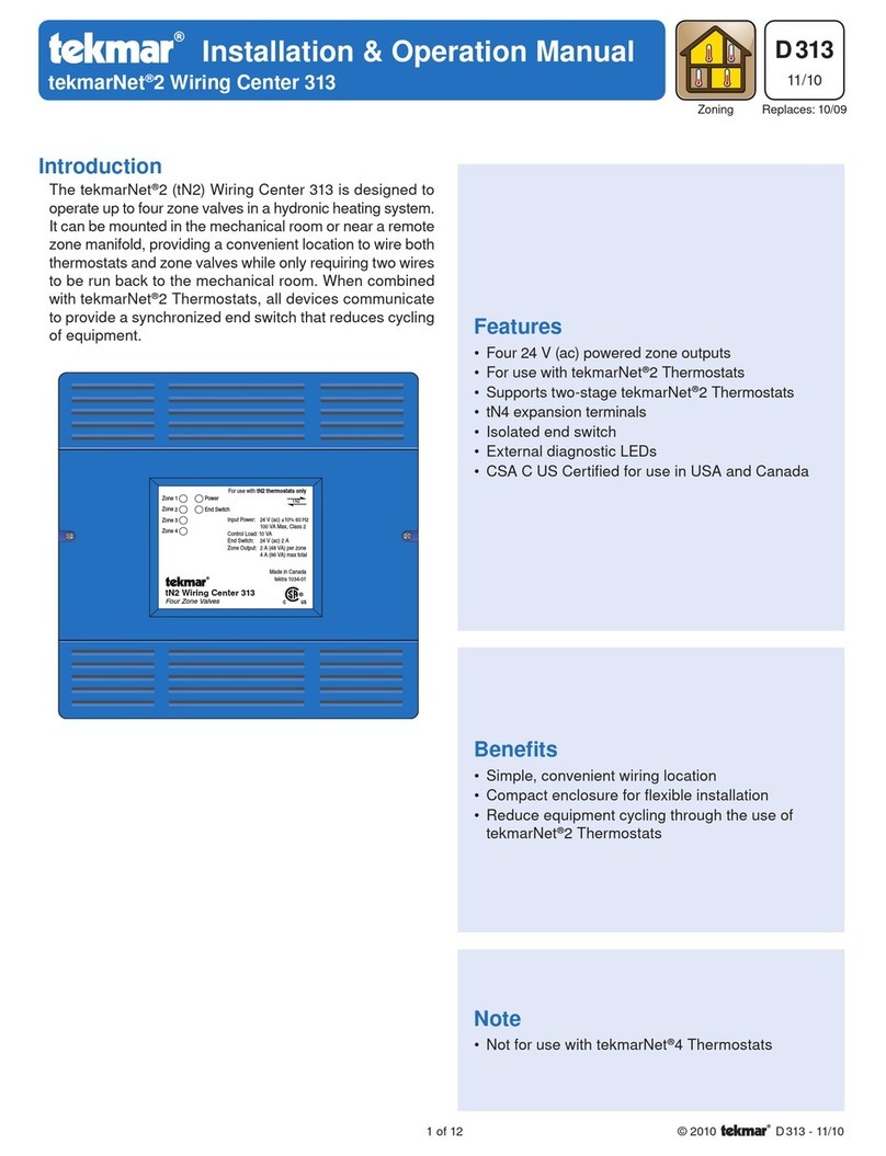
Tekmar One Stage Boiler Control 253 User manual

One Stage Boiler Control 253
D 253
- Data Brochure 05/97
The One Stage Boiler Control 253 is a microprocessor-based control designed to regulate the sup-
ply water temperature from a single boiler based on the outdoor temperature. To avoid boiler short
cycling and large temperature swings, the 253 is able to continuously adjust the boiler differential.
The 253 includes functions such as Warm Weather Shut Down (WWSD), Minimum Boiler setting, and
a Starting Temperature setting. The control has a digital, liquid crystal display (LCD) that normally
displays the Boiler Supply temperature, but can display other temperatures and settings.
Control Strategy . . . . . . . . . . . . pg. 1 Testing the Control . . . . . . . pg. 6
Sequence of Operation . . . . . . . pg. 2 Error Messages. . . . . . . . . . . pg. 7
Installation . . . . . . . . . . . . . . . . . pg. 3 Technical Data . . . . . . . . . . . pg. 8
Settings . . . . . . . . . . . . . . . . . . . pg. 4 Limited Warranty . . . . . . . . . pg. 8
Input
24 V (ac)
Power Supply
Input
Outdoor Sensor
Included
Output
Boiler
Input
Boiler Sensor
Included
Item
4
Boiler
56
T
1
H11461
PRGM
FC
WWSD
24 V 50/60 Hz 3 VA
120 V (ac) 5 A1/6 hp
pilot duty 240 VA
Power:
Boiler Relay:
Mar 97
31000265
- displays control settings
- displays hundreds of hours of use
- displays hours of use
Press & Hold:
Item
One Stage Boiler
Control 253
23
Com
Sen
Boil
Sen
Out
Sen
No power
78
Power
R+ C-
NRTL /C
LR 58223
R
USE
(hours)
Minimum Boiler
Differential
Curve
Boiler Supply
Target Boiler
Starting Temp.
H. Dem
Boiler
OUTDOOR
Signal wiring must be
rated at least 300V
Input
Heat Demand
Made in Canada
Control Strategy
OUTDOOR RESET
In order to properly control a hot water heating system, the heat supplied
to the building must equal the heat lost by the building.
• The heat supplied to a building is proportional to the temperature of the
supplywaterandthesurfaceareaoftheheatingelement.Asmallsurface
area such as baseboard radiators requires a higher water temperature
than a larger surface area such as radiant floors.
• The heat lost from a building is dependent on the outdoor temperature,
as well as other factors. As the outdoor temperature drops, the building
heat loss increases.
Constant
Room Temperature
Outdoor
Temperature
Drop
Heat
Loss
Increase
WWSD
Boiler Supply
Target Boiler
Starting Temp.
Minimum Boiler
Differential
Curve
H. Dem
Boiler
R
Use
(hours)
One Stage Boiler
Control 253
Item
NRTL/C
LR 58223
F

2
Heating Curve
Operation of a hot water heating system can generally be improved by modulating the
supplywatertemperatureas theoutdoortemperaturechanges. Usingthisapproach,the
heat lost from the building is matched by the heat input to the building. A tekmar reset
control utilizes a heating curve to set the relationship between outdoor temperature and
supply water temperature. The heating curve determines the amount the supply water
temperature is raised for every 1°drop in outdoor air temperature, and it is determined
fromthestartingpointandthesystemdesignconditions.Theheatingcurveissometimes
called an outdoor reset ratio.
Heating Curve Starting Point
All heating curves begin at the heating curve starting point. This point is a combination
of an adjustable starting water temperature setting and the WWSD point.
Starting Temperature
When the outdoor temperature is cold
enough to start the heating system, the
control should provide a preset starting
supply water temperature. If the Starting
Temperaturesettingisadjusted,theheat-
ing curve is shifted vertically.
Warm Weather Shut Down (WWSD)
When the outdoor air temperature is
warmer than the Warm Weather Shut
Down setting, no additional heat is re-
quired in the building; therefore, the heat-
ing system can be shut down. When the
WWSDtemperatureisadjusted,theheat-
ing curve is shifted horizontally.
BOILER OPERATION
The supply water temperature from a boiler can be controlled by cycling the boiler on and
off. Modulation of the boiler’s operating temperature in hot water heating systems not only
providesmorecomfortbutalsoofferssignificantenergysavings.Thecoolertheboilerruns,
the more efficient it is due to less heat losses up the flue and reduced boiler jacket losses.
Minimum Boiler Supply
Most boilers require a minimum supply water temperature in order to prevent corrosion
fromfluegascondensation.Thecontrolshouldthereforeonlymodulatetheboilersupply
watertemperaturedownto the boiler manufacturer’s minimum recommended operating
temperature. Some boilers are designed to condense and should be operated
at low
water temperatures as much as possible for maximum efficiency.
Differential
Anon/offboilermustbeoperatedwithadifferentialinordertoprevent
short cycling. When the supply water temperature drops below the
bottom rail of the differential, the boiler is turned on. The boiler is then
kept on until the supply water temperature rises above the top rail of
the differential. If the differential is too wide, there can be large supply
watertemperatureswings;however,ifthedifferentialistoonarrow,the
boiler short cycles and operates inefficiently. This control can auto-
matically calculate the boiler differential in order to achieve an appro-
priatebalancebetweentemperatureswingsandboilerefficiency.This
also permits the control to adapt to changing loads and conditions.
Sequence of Operation
POWERING UP THE CONTROL
Afterthe253ispoweredup,asoftwareversionnumberisdisplayedandisfollowedbya test
ofallLCDsegments.After5secondsthecontroldisplaystheboilersupplywater temperature.
HEAT DEMAND
The 253 requires a heat demand in order to control the boiler supply water temperature.
Whenterminal
T
is connected toterminal
C-
(6 and 8),the control receivesa heat demand.
The
H. Dem
pointer flashes for up to 30 seconds and then turns on solid. The flashing
represents a built in delay for turning on the boiler.
Outdoor air temperature
50
(10) 30
(-1) 10
(-12) -10
(-23)
70
(21)
3.6 3.0 2.4 2.0 1.6
1.2
0.8
0.4
1.0
0.6
90
(32)
Heating
Curve
Starting
Point
°F
(°C)
Supply water temperature
110
(43)
70
(21)
90
(32)
210
(99)
170
(77)
150
(65)
130
(54)
190
(88)
0.2
Outdoor air temperature
50
(10) 30
(-1) 10
(-12) -10
(-23)
70
(21)
90
(32)
WWSD
Temperature
°F
(°C)
Supply water temperature
110
(43)
70
(21)
90
(32)
210
(99)
170
(77)
150
(65)
130
(54)
190
(88)
2.0
WWSD Adjustment
Outdoor air temperature
50
(10) 30
(-1) 10
(-12) -10
(-23)
70
(21)
2.0
90
(32)
Starting
Water
Temperature
°F
(°C)
Supply water temperature
110
(43)
70
(21)
90
(32)
210
(99)
170
(77)
150
(65)
130
(54)
190
(88)
Starting Water Temperature Adjustment
Outdoor air temperature
50
(10) 30
(-1) 10
(-12) -10
(-23)
70
(21)
3.6 3.0 2.0 1.6
1.2
0.8
0.4
0.6
90
(32) °F
(°C)
Supply water temperature
110
(43)
70
(21)
90
(32)
210
(99)
170
(77)
150
(65)
130
(54)
190
(88)
2.4
1.0
Heating
Curve
Starting
point
Minimum Boiler
Supply Setting
130°F
0.2
Supply Water Temperature
Time
Differential = 10°F (5°C)
165°F(74°C)
Boileroff
Boileron
155°F (68°C)
160°F (71°C)
Boileroff
Boileron
Zone Valve Motor
End Switches
M
M
T
o contro
l
C
R

3
WARM WEATHER SHUT DOWN (WWSD)
When the outdoor temperature rises above the WWSD setting, the 253 flashes the
WWSD
pointer and turns off the
Boiler
relay (4 and 5).
BOILER OPERATION
Whilethe253hasaheatdemand,thesystemsupplywatertemperatureiscontrolledbyturningtheboileronandoff.The253calculates
the target supply water temperature based on the outdoor temperature, the heating curve setting, the starting temperature setting, the
WWSD setting, and the minimum boiler setting.
The boiler operates around a differential that is either manually set or automatically controlled by the 253. If the differential is manually
fixedandaheatdemandispresent,thereisa60 secondoff timedelay ofthe boilertoallowforprepurgingofthesystemandprevention
of boiler short cycling. The off time delay decreases to 20 seconds if the automatic differential is set. The automatic boiler differential
increases system efficiency by adjusting to changing loads.
Maximum Boiler Supply
The 253 does not allow the target boiler supply water temperature to exceed 220°F
(104°C) minus half the differential. If the boiler supply temperature reaches 220°F
(104°C), the control turns off the boiler.
Minimum Boiler Supply
The 253 has a
Minimum Boiler
setting which selects a minimum target boiler supply
temperatureinordertopreventcorrosionfromfluegascondensation.Duringmildoutdoor
conditions,theboilercyclesaroundtheminimumboilersetting.Thisprogrammedfunction
has an
Off
setting for condensing and electric boilers. The control flashes the
Minimum
Boiler
pointer when operating at the minimum setting.
WWSD
Boiler Supply
Target Boiler
Starting Temp.
Minimum Boiler
Differential
Curve
F
OUTDOOR
H. Dem
Boiler
Installation
Caution
Improperinstallationandoperationofthiscontrolcouldresultindamagetotheequipmentandpossiblyevenpersonalinjury.
It is your responsibility to ensure that this control is safely installed according to all applicable codes and standards. This
electronic control is not intended for use as a primary limit control. Other controls that are intended and certified as safety
limits must be part of the control circuit.
STEP ONE GETTING READY
Checkthecontentsofthispackage.Ifanyofthecontentslistedaremissingordamaged,pleasecontactyourwholesalerortekmarsales
representative for assistance.
Type 253 includes:
• One Stage Boiler Control 253 • One Outdoor Sensor 070
• One Universal Sensor 071
• Data Brochures D 253, D 001, D 070
• Application Brochures A 253
Other information available:
• Essays
Note Carefullyread thedetailsof theSequenceof Operationsectioninthisbrochuretoensure thatyouhave chosentheproper control
for your application.
STEP TWO MOUNTING
The control is mounted in accordance with the instructions in the Data Brochure D 001.
STEP THREE ROUGH-IN WIRING
All electrical wiring terminates in the two wiring chambers on the control. If the control is to be mounted on an electrical box, the wiring
can be roughed-in at the electrical box prior to installation of the control. (See Brochure D 001.) Standard 18 AWG solid wire is
recommended for all low voltage wiring.
Power must not be applied to any of the wires during the rough-in wiring stage.
• Install the Outdoor Sensor 070 and the Universal Sensor 071 according to the instructions in the Data Brochure D 070 and run the
wiring back to the control mounting location.
• Run the wiring from the boiler to the control mounting location.
• Run the wires from the heat demand circuit to the control mounting location.
• Run the wires from the 24 V (ac) power source to the control mounting location.
Use a clean power source to ensure proper
operation.
Outdoor air temperature
50
(10) 30
(-1) 10
(-12) -10
(-23)
70
(21)
3.6 3.0 2.0 1.6
1.2
0.8
0.4
0.6
90
(32) °F
(°C)
Supply water temperature
110
(43)
70
(21)
90
(32)
210
(99)
170
(77)
150
(65)
130
(54)
190
(88)
2.4
1.0
Starting
point
Minimum Boiler
Supply Setting
140°F
0.2
230
(110)
Maximum Boiler
Temperature 220°F

4
STEP FOUR TESTING THE WIRING
No wires should be connected to the control during testing.
A good quality electrical test meter, capable of reading from at least 0 — 200 V (ac) and at least 0 — 2,000,000 Ohms, is essential to
properly test the wiring and sensors.
Test the Sensors
Testthesensors according tothetesting procedure in DataBrochureD 070. Ensurethe
sensor wires are not connected to the control terminals.
Test the Power Supply
Make sure exposed wires and bare terminals are not in contact with other wires or
grounded surfaces. Turn on the power and measure the voltage across the 24 V (ac)
power supply. The voltmeter should read between 22 and 26 Volts.
Test the Powered Inputs
Measure the voltage between the heat demand wire and the power wire that goes to C- of the control. The voltmeter should read
between 22 and 26 volts when there is a call for heat.
Test the Outputs
Short the boiler wires and power up the boiler circuit; the boiler should fire. Remove power from the boiler circuit.
STEP FIVE ELECTRICAL CONNECTIONS TO THE CONTROL
The installer should confirm that no voltage is present at any of the wires.
OutputConnections
Boiler Relay
Connect the 120 V (ac) or 24 V (ac) boiler circuit directly to the
Boiler
relay (4 and 5)
terminals. These terminals go to dry relay contacts.
PoweredInputConnections
24 V (ac) Power
Connectthe24V(ac)powersupplytoterminals
PowerR+—C-
(7and8)onthecontrol.
Heat demand
ConnecttheC-sideofthetransformertoterminal
T
(6)throughaswitchingdevice.This
provides a heat demand to the control.
Caution
The C- of the same transformer used to power up the control must be used
to provide the heat demand.
Sensor and Unpowered Input Connections
Do not apply power to these terminals as this will damage the control.
Outdoor Sensor
Connect the two wires from the Outdoor Sensor 070 to the terminals
Com Sen
—
Out
Sen
(1 and 3). The Outdoor Sensor measures the outdoor air temperature.
Boiler Sensor
ConnectthetwowiresfromtheBoilerSensor071totheterminals
ComSen—BoilSen
(1 and 2). The Boiler Sensor measures the supply water temperature going from the
boiler to the system.
Settings
Before adjusting the settings, read through the sequence of operation to ensure that you understand how the control operates. The
following page describes how to program these settings into the control once it has been powered up.
STEP SIX ESSENTIAL CONTROL SETTINGS
StartingTemp.
The
Starting Temp.
setting is the starting supply water temperature of the heating curve, and can be adjusted from 35 to 150°F (2
to 66°C). In applications where fan coils are used, the
Starting Temp
. may need to be set higher to prevent cold drafts.
Warm Weather Shut Down (WWSD
)
The WWSD can be adjusted from 35 to 85°F (2 to 29°C). The boiler will be shut down when the outdoor temperature is warmer than
this setting. Factory setting is 68°F (20°C).
Ω
Ω
231
Com
Sen
Boil
Sen
Out
Sen
Heat
Demand
Switches
Class II
Transformer CR
5
R+ C-
T
6784
Power
Boiler
24 V (ac)
5
R+ C-
T
6784
Power
Boiler
231
Com
Sen
Boil
Sen
Out
Sen

5
Differential
Thedifferentialadjustment sets how fartheactual boiler supply watertemperaturemay deviate from thedesiredtemperature before
the boiler is turned on or off, and it is determined by the flow rate through the system pump relative to the heat output by the boiler.
TheDifferentialcanbe adjusted to Ad (Auto differential) or from 2 to42°F(1to 23°C). The following formula can be usedtocalculate
the desired differential:
Whentheadjustmentissetto
Ad(AutoDifferential
),thedifferentialiscontinuouslycalculatedbythecontrol,andvariesastheheating
load changes. This setting is suggested and therefore it is a factory setting.
Minimum Boiler Supply
Mostboilersrequireaminimumoperatingtemperaturetopreventcorrosion from flue gas condensation. The
MinimumBoiler
setting
should be programmed to the lowest supply water temperature at which the boiler can operate without causing the boiler flue gases
to condense. Consult the boiler manufacturer for recommended minimum boiler supply temperatures. Some typical settings are as
follows:
• Steel fire tube boiler ….......... 140 to 160°F (60 to 71°C) • Condensing boiler ................. Off
• Cast iron boiler ….................. 135 to 160°F (57 to 71°C) • Electric boiler ........................ Off
• Copper tube boiler …............. 125 to 150°F (52 to 66°C)
Curve (Heating Curve)
TheHeatingCurvesettingdeterminesthenumberofdegreesthesupply watertempera-
ture is raised for every one degree drop in outdoor temperature. The
Curve
setting can
be calculated from the following formula.
design supply temperature – Starting water temperature
Heating Curve =
WWSD – design outdoor temperature
Curve (Heating Curve) Setting Examples:
Example #1 Example #2 Example #3
Design Supply Water Temperature 180°F (82°C) 180°F (82°C) 180°F (82°C)
Starting Water Temperature 70°F (21°C) 150°F (66°C) 160°F (71°C)
Design Outdoor Temperature -5°F (-21°C) -5°F (-21°C) -5°F (-21°C)
Warm Weather Shut Down (WWSD) 70°F (21°C) 65°F (18°C) 60°F (16°C)
Minimum Boiler 130°F (54°C) 130°F (54°C) 130°F (54°C)
Differential = Example: = 10°F (6°C)
Btu/hr input 100,000 Btu/hr
System US GPM x 50 20 US GPM x 500
Outdoor air temperature
55
(13) 40
(4) 25
(-4) 10
(-12)
70
(21) °F
(°C)
Supply water temperature
110
(43)
70
(21)
90
(32)
210
(99)
170
(77)
150
(65)
130
(54)
190
(88)
-5
(-21)
Example #3
Example #2
Example #1
WWSD
Design
Condition
Starting
Temp.
Outdoor air temperature
50
(10) 30
(-1) 10
(-12) -10
(-23)
70
(21)
3.6 3.0 2.4 2.0 1.6
1.2
0.8
0.4
1.0
0.6
90
(32)
Starting
Point
°F
(°C)
Supply water temperature
110
(43)
70
(21)
90
(32)
210
(99)
170
(77)
150
(65)
130
(54)
190
(88)
0.2
=
Example #1
Heating Curve = 180 — 70°F (82 — 21°C)
70 — (-5°F) (21 — (-21°C)) 110°F (61°C)
75°F (42°C) = 1.5
=
Example #2
Heating Curve = 180 — 150°F (82 — 66°C)
65 — (-5°F) (18 — (-21°C)) 30°F (16°C)
70°F (39°C) = 0.4
=
Example #3
Heating Curve = 180 — 160°F (82 — 71°C)
60 — (-5°F) (16 — (-21°C)) 20°F (11°C)
65°F (37°C) = 0.3
Control Adjustments
Starting Temp.: __________________________________________
WWSD: ________________________________________________
Curve: _________________________________________________
Differential: _____________________________________________
Minimum Boiler: _________________________________________

6
VIEWING
The control automatically goes back to viewing when the buttons are left alone for 20 seconds
POWER ON
PROGRAMMING
Press and Release the
"Item" button until the
Boiler Supply
pointer is
turned on. The Boiler
Supply temperature will
be displayed.
WWSD
Boiler Supply
Target Boiler
Starting Temp.
Minimum Boiler
Differential
Curve
F
H. Dem
Boiler
WWSD
Boiler Supply
Target Boiler
Starting Temp.
Minimum Boiler
Differential
Curve
F
Press and Hold the
"Item" button. The
programmed settings will
be displayed
sequencially.
H. Dem
Boiler
WWSD
Boiler Supply
Target Boiler
Starting Temp.
Minimum Boiler
Differential
Curve
Press and Hold the
button. The boiler hours
(xx) of use will be
displayed.
Press and Hold the
button. The hundreds of
boiler hours (xx00) of use
will be displayed.
H. Dem
Boiler
WWSD
Boiler Supply
Target Boiler
Starting Temp.
Minimum Boiler
Differential
Curve
Press and Hold the
and buttons for 3
seconds to clear the
boiler hours of
operation.
H. Dem
Boiler
WWSD
Boiler Supply
Target Boiler
Starting Temp.
Minimum Boiler
Differential
Curve
F
OUTDOOR
H. Dem
Boiler
Press and Release the
"Item" button until the
Outdoor
element is
turned on. The Outdoor
temperature will be
displayed.
Once in the PRGM
mode, the programmed
Starting Temp.
pointer
will flash. Use the and
buttons to set the
desired starting
temperature
Press and Release the
"Item" button until the
WWSD
pointer flashes.
Use the and buttons
to set the desired
temperature.
WWSD
Boiler Supply
Target Boiler
Starting Temp.
Minimum Boiler
Differential
Curve
PRGM
Press and Release the
"Item" button until the
Curve
pointer flashes.
Use the and buttons
to set the desired ratio.
H. Dem
Boiler
WWSD
Boiler Supply
Target Boiler
Starting Temp.
Minimum Boiler
Differential
Curve
PRGM
Press and Release the
"Item" button until the
Differential
pointer
flashes. Use the and
buttons to set the control
into
Ad
(auto differential)
or a fixed value.
H. Dem
Boiler
WWSD
Boiler Supply
Target Boiler
Starting Temp.
Minimum Boiler
Differential
Curve
PRGM
F
Press and Release the
"Item" button until the
Minimum Boiler
pointer
flashes. Use the and
buttons to set the
desired temperature.
H. Dem
Boiler
WWSD
Boiler Supply
Target Boiler
Starting Temp.
Minimum Boiler
Differential
Curve
PRGM
C
Press and Release the
"Item" button until the °F
or °C element flashes.
Use the and buttons
to set the scale to °F or
°C.
H. Dem
Boiler
Once in operating mode,
the control will display the
boiler supply temperature
and will turn on the
Boiler
Supply
pointer.
WWSD
Boiler Supply
Target Boiler
Starting Temp.
Minimum Boiler
Differential
Curve
F
H. Dem
Boiler
WWSD
Boiler Supply
Target Boiler
Starting Temp.
Minimum Boiler
Differential
Curve
PRGM
FC
When the control is
powered-up, a version
number followed by all
display elements are
turned on. After
approximately 5 seconds,
the control automatically
goes into operating mode.
OUTDOOR
H. Dem
Boiler
WWSD
Boiler Supply
Target Boiler
Starting Temp.
Minimum Boiler
Differential
Curve
F
Press and Release the
"Item" button. The target
boiler temperature and
the
Target Boiler
pointer
will be displayed. A series
of lines are displayed if no
heat is required.
H. Dem
Boiler
Target Boiler Supply Temperature
Outdoor Temperature
Actual Boiler Supply Temperature
Programmed Settings
Boiler Running Hours
Clearing Boiler Running Hours
Starting Temperature
WWSD
WWSD
Boiler Supply
Target Boiler
Starting Temp.
Minimum Boiler
Differential
Curve
PRGM
F
H. Dem
Boiler
WWSD
Boiler Supply
Target Boiler
Starting Temp.
Minimum Boiler
Differential
Curve
PRGM
F
H. Dem
Boiler
To enter the programming mode Press and Hold simultaneously, the "Item", , and buttons. The PRGM element will turn on.
Heating Curve Minimum Boiler
Differential Fahrenheit / Celsius
The control will flash the
WWSD
pointer if the
outdoor temperature is
greater than the WWSD
setting. If the control is
operating at minimum,
the
Minimum Boiler
pointer will flash.
WWSD
Boiler Supply
Target Boiler
Starting Temp.
Minimum Boiler
Differential
Curve
F
H. Dem
Boiler
OUTDOOR
All settings will be saved even during power down of the control
Testing the Control
STEP SEVEN TESTING
Iftestingisrequired withtheOneStage BoilerControl253,follow thetestingprocedurein stepfourofthe installationprocedureonpage
4 of this brochure.
STEP EIGHT TROUBLESHOOTING
As in any troubleshooting procedure, it is important to isolate a problem as much as possible before proceeding. The Error Messages
greatlysimplifytroubleshootingofthe253.Whenthe controldisplaysanerrormessage, identifythefaultfromthe look-uptableon page
7 and follow standard testing procedures to confirm the problem. If you suspect a wiring fault, return to steps three, four and five and
carefully check all external wiring and wiring connections.
Sensor and Internal Faults
• Ifanoutdoorsensorfaultoccurs,the253willassumeafixedoutdoortemperatureof32°F(0°C)andwilltargettheappropriatesupply
water temperature. An error message is displayed.
• If a supply sensor fault occurs, the 253 turns the boiler off and displays an error message.
• If an internal control fault occurs, the 253 operates as normal but displays an error message.

7
Adjustment of Settings
• If the outdoor temperature is cold and the rooms are cold, increase the
Curve
setting by 0.1 per day.
• If the outdoor temperature is near the WWSD temperature and the rooms are cold, increase the
Starting Temp
. setting.
• If the boiler is cycling too often, increase the
Differential
setting or set control to
Ad
(Auto Differential).
STEP NINE BEFORE YOU LEAVE
• Install the wiring cover over the wiring chamber and secure it with the screw provided.
• Place the front cover on the control and snap it into place.
• Place this brochure, and all other brochures relating to the installation, in the protective plastic bag supplied with the control.
• Place the bag in a conspicuous location near the control for future reference.
• It is important to explain the operation of this control within the system to the end user, and to anyone else who may be operating
the system.
Error Messages
Whenever a fault is detected, an error message will be displayed to indicate the location of the problem. For detailed sensor testing
instructions see Data Brochure D 070.
Refer to the troubleshooting section above for operation details
WWSD
Boiler Supply
Target Boiler
Starting Temp.
Minimum Boiler
Differential
Curve
OUTDOOR
H. Dem
Boiler
Outdoor Sensor
Open Circuit
WWSD
Boiler Supply
Target Boiler
Starting Temp.
Minimum Boiler
Differential
Curve
OUTDOOR
H. Dem
Boiler
WWSD
Boiler Supply
Target Boiler
Starting Temp.
Minimum Boiler
Differential
Curve
OUTDOOR
H. Dem
Boiler
WWSD
Boiler Supply
Target Boiler
Starting Temp.
Minimum Boiler
Differential
Curve
H. Dem
Boiler
Outdoor Sensor
Short Circuit
OUTDOOR
WWSD
Boiler Supply
Target Boiler
Starting Temp.
Minimum Boiler
Differential
Curve
H. Dem
Boiler
WWSD
Boiler Supply
Target Boiler
Starting Temp.
Minimum Boiler
Differential
Curve
H. Dem
Boiler
Internal
Fault
WWSD
Boiler Supply
Target Boiler
Starting Temp.
Minimum Boiler
Differential
Curve
H. Dem
Boiler
WWSD
Boiler Supply
Target Boiler
Starting Temp.
Minimum Boiler
Differential
Curve
H. Dem
Boiler
Boiler Sensor
Short Circuit
WWSD
Boiler Supply
Target Boiler
Starting Temp.
Minimum Boiler
Differential
Curve
H. Dem
Boiler
Boiler Sensor
Open Circuit
WWSD
Boiler Supply
Target Boiler
Starting Temp.
Minimum Boiler
Differential
Curve
H. Dem
Boiler
flashes
between flashes
between flashes
between flashes
between flashes
between
Notes

8
The installer must ensure that this control and its wiring are isolated and/or shielded from strong sources of electromagnetic noise.
Conversely, this Class B digital apparatus complies with Part 15 of the FCC Rules and meets all requirements of the Canadian
Interference-CausingEquipmentRegulations.However, if this control does cause harmful interference to radioortelevisionreception,
which can be determined by turning the control off and on, the user is encouraged to try to correct the interference by reorienting or
relocating the receiving antenna, relocating the receiver with respect to this control, and/or connecting the control to a different circuit
from that to which the receiver is connected.
Cet appareil numérique de la classe B respecte toutes les exigences du Règlement sur le matériel brouilleur du Canada.
All specifications are subject to change without notice.
Printed in Canada on recycled paper.
Product design, software and literature are Copyright © 1997 by:
tekmar Control Systems Ltd. and tekmar Control Systems, Inc.
Control Systems
tekmar Control Systems Ltd., Canada
tekmar Control Systems, Inc., U.S.A.
Head Office: 4611 - 23rd Street
Vernon, B.C. Canada V1T 4K7
Tel. (250) 545-7749 Fax. (250) 545-0650
Limited Warranty
The liability of tekmar Control Systems Ltd. and tekmar
ControlSystems, Inc.("tekmar")underthiswarranty islimited.Pleasereadand
understand the conditions appearing herein.
tekmarwarrants each tekmar product againstdefects inworkmanship and materials,
when the product is installed and used in compliance with tekmar's instructions. The
warranty period is for a period of twenty-four (24) months from the production date if
the product is not installed during that period, or twelve (12) months from the
documented date of installation if installed within twenty-four (24) months from the
production date, but in any event the warranty period shall not extend beyond thirty-
six (36) months from the production date. During the warranty period, tekmar will, at
its discretion, either repair at no charge, exchange or give credit for the defective
product, provided the product is returned to tekmar.
Theliabilityoftekmarshallbelimitedtothecostofpartsand labourprovidedbytekmar
tocorrectdefectsinmaterialsand/orworkmanshiportotheexchangeofthedefective
productforareplacementproductortothegrantingofcreditlimitedtotheoriginalcost
of the product, at tekmar's discretion, and such repair, exchange or credit shall be
deemed to be the sole remedy available from tekmar. This warranty does not cover
the cost of the parts or labour to remove or to transport the defective product, or to
reinstalltherepairedorreplacementproduct.Returnedproductsthatarenotdefective
are not covered by this warranty.
This warranty does not apply if the product has been damaged by accident, abuse,
misuse, negligence, fire, Act of God, or has been damaged by modifications,
alterations or attachments made subsequent to purchase which have not been
authorized by tekmar, or if the product was not installed in compliance with the
local codes and ordinances, or if due to defective installation of the product.
The warranty applicable to a product is as set out in the statement of warranty
policy (the "Warranty") above, receipt of which is hereby acknowledged. The
liability of tekmar is limited to those obligations identified in the warranty as
obligations of tekmar. The warranty is understood to be in substitution for any
loss, costs or damages for which tekmar might otherwise be liable at law or in
equity and in particular, in lieu of any liability for fundamental breach of
contract.
tekmar disclaims any responsibility for losses, expenses, inconveniences, or
any special, indirect, secondary, incidental or consequential damages arising
from ownership or use of any items subject to any claim hereunder, regardless
of whether such claim is stated in contract, tort or strict product liability.
This warranty is in lieu of all other warranties, express or implied, including,
withoutlimitation,warrantiesofmerchantability,fitness foraparticularpurpose,
durability or description of the product, its non-infringement of any relevant
patentsortrademarks,anditscompliancewithornon-violationofanyapplicable
environmental, health or safety legislation. No implied warranties shall extend
beyond twenty-four (24) months from the production date.
Some states or provinces do not allow limitations on how long an implied warranty
lasts, so the above limitation may not apply to you. This warranty gives you specific
legal rights, and you may also have other rights which vary from state to state or
province to province.
ProductReturnProceduresProductsthatarebelievedtohavedefectsinworkmanship
or materials must be returned, together with a written description of the defect, to the
tekmar representative for that territory. If the address of the representative is not
known, please request it from tekmar at the telephone number listed below.
Limited Warranty and Product Return Procedure
Technical Data
One Stage Boiler Control 253
Literature — A 000, A 253's, D 253, D 001, D 070
Control — Microprocessor PI control; This is not a safety (limit) control.
Packaged weight — 1.1 lb. (500 g), Enclosure C, PVC plastic
Dimensions — 4-3/4” H x 2-7/8” W x 7/8” D (120 x 74 x 22 mm)
Approvals — CSA NRTL /C; Meets ICES & FCC regulations for EMI/RFI.
Ambient conditions — Indoor use only, 15 to 120°F (-10 to 50°C), < 90% RH non-
condensing.
Power supply —
Class 2, 24 V ±10% 50/60 Hz 3 VA
Relays — 120 V (ac) 5 A 1/6 hp, pilot duty 240 VA 2 A
Sensors — NTC thermistor, 10 kW @ 77°F (25°C ±0.2°C) ß=3892
included: Outdoor Sensor 070 and Universal Sensor 071.
Starting Temp. —
35 to 150°F (2 to 66°C)
WWSD
— 35 to 85°F (2 to 29°C)
Curve
— 0.2 to 3.6
Differential
— Auto, 2 to 42°F (Auto, 1 to 24°C)
Minimum Boiler
— Off, 70 to 170°F (Off, 21 to 77°C)
Item
4
Boiler
56
T
1
H11461
PRGM
FC
WWSD
24 V 50/60 Hz 3 VA
120 V (ac) 5 A1/6 hp
pilot duty 240 VA
Power:
Boiler Relay:
Mar 97
31000265
- displays control settings
- displays hundreds of hours of use
- displays hours of use
Press & Hold:
Item
One Stage Boiler
Control 253
23
Com
Sen
Boil
Sen
Out
Sen
No power
78
Power
R+ C-
NRTL /C
LR 58223
R
USE
(hours)
Minimum Boiler
Differential
Curve
Boiler Supply
Target Boiler
Starting Temp.
H. Dem
Boiler
OUTDOOR
Signal wiring must be
rated at least 300V
Made in Canada
Table of contents
Other Tekmar Control System manuals

Tekmar
Tekmar 062 User manual

Tekmar
Tekmar 364 User manual

Tekmar
Tekmar tekmarNet2 314 User manual

Tekmar
Tekmar 654 User manual

Tekmar
Tekmar 313 User manual

Tekmar
Tekmar 150 User manual

Tekmar
Tekmar Zone Control 369 User manual

Tekmar
Tekmar tN2 house control 400 User manual

Tekmar
Tekmar Pump Sequencer 132 User manual

Tekmar
Tekmar Universal Reset Control 363 User manual
Popular Control System manuals by other brands

Nidec
Nidec MCE iControl user guide

Siemens
Siemens SIMATIC PCS 7 Operation and maintenance

Sentex
Sentex Infinity Design guide

heat-timer
heat-timer DIGI-SPAN Elite MC Series Installation and operation manual

EUCHNER
EUCHNER MSM-1-R-CKS2-FLX Series operating instructions

GCS
GCS CYSCAN Installation and maintenance guide