Melchor Varela SARK-110 User manual

This document is licensed under a Creative Commons Attribution-NonCommercial-ShareAlike 3.0 Unported License.
© Melchor Varela – EA4FRB 2011-2012
SARK
SARKSARK
SARK-
--
-110
110110
110
Vector Impedance Antenna Analyzer
User’s Manual
Revision 0.7
Updated to Firmware Version 0.6.x

SARK
SARKSARK
SARK-
--
-110
110110
110
User’s Manual
Rev 0.7 Sept 3
rd
, 2012 - 2 - © Melchor Varela – EA4FRB 2011-2012
Contents
1
INTRODUCTION.......................................................................................................................3
2
FEATURES...............................................................................................................................4
3
OPERATING THE SARK-110 ..................................................................................................5
3.1
S
CREEN
L
AYOUT
..................................................................................................................5
3.2
M
EANS OF
I
NPUT
..................................................................................................................6
3.3
C
HANGING THE
C
ENTER
F
REQUENCY
....................................................................................7
3.4
C
HANGING THE
S
PAN
...........................................................................................................7
3.5
F
REQUENCY
P
RESETS
..........................................................................................................8
3.6
U
SING
M
ARKERS
..................................................................................................................9
3.7
C
HANGING
V
ERTICAL
A
XIS
P
ARAMETER
..............................................................................11
3.8
S
AVING AND
R
ECALLING
M
EASUREMENTS
...........................................................................12
3.9
T
AKING
S
CREENSHOTS
......................................................................................................14
3.10
C
HANGING THE
O
PERATING
M
ODE
..................................................................................14
3.11
C
HANGING THE
S
ETTINGS
...............................................................................................15
4
ANTENNA TEST MODE.........................................................................................................19
5
SMITH CHART MODE............................................................................................................20
6
SINGLE FREQUENCY MODE ...............................................................................................21
7
CABLE TEST MODE..............................................................................................................23
8
SPECIFICATIONS ..................................................................................................................25
9
PRECAUTIONS......................................................................................................................28
10
ACKNOWLEDGMENTS .....................................................................................................29
11
REGULATORY WARNING.................................................................................................29
APPENDIX A:
FUNDAMENTAL PARAMETERS....................................................................30
APPENDIX B:
UPDATING THE FIRMWARE .........................................................................31
APPENDIX C:
OSL CALIBRATION........................................................................................32
APPENDIX D:
DETECTOR CALIBRATION............................................................................35
APPENDIX E:
SCALE PRESETS ...........................................................................................38
APPENDIX F:
CALIBRATION LOADS MANUFACTURING..................................................40

SARK
SARKSARK
SARK-
--
-110
110110
110
User’s Manual
Rev 0.7 Sept 3
rd
, 2012 - 3 - © Melchor Varela – EA4FRB 2011-2012
1 Introduction
The SARK-110 Antenna Analyser is a pocket size instrument providing fast and accurate
measurement of the vector impedance, VSWR, vector reflection coefficient, return loss, and R-
L-C (as series or parallel equivalent circuits).
Typical applications include checking and tuning antennas, impedance matching, component
test, cable fault location, measuring coaxial cable losses, and cutting coaxial cables to precise
electrical lengths.
The SARK-110 features a Direct Digital Synthesis (DDS) generator with a range of 0.1 to 230
MHz and a frequency resolution of 1 Hz. The instrument has full vector measurement capability
and accurately resolves the resistive, capacitive and inductive components of a load. The
measurement reference plane is automatic adjusted via the Open/Short/Load calibration
standard to enable the accurate impedance measurements at the end of an intermediate coaxial
cable.
The user interface based on a color display has been designed to be intuitive and easy to use.
The graphical impedance displays provide a quick view of the antenna impedance
characteristics on a user selected sweep range. This includes the graphical plot of two user
selectable parameters in a Cartesian diagram or the complex reflection coefficient in Smith chart
form. Two markers, either user positionable or in an automatic tracking mode, help to speed-up
the measurements.
Besides it is included a single frequency measurement mode which presents the complete
impedance parameters at a user selectable frequency.
In addition, the analyzer features a FDR (Frequency Domain Reflectometer) mode which is
intended for the location of faults in coaxial cables.
The analyzer features an internal 2MB flash disk for the storage and recall of the measured
parameters, screenshots, analyzer configuration, and firmware updates. This disk is accessible
via USB so the measured parameters can be also retrieved from the PC and analyzed from the
ZPLOTS spreadsheet program.
Let us know your suggestions in http://sark110.ea4frb.eu as we are highly motivated to extend
this device based on community requests.

SARK
SARKSARK
SARK-
--
-110
110110
110
User’s Manual
Rev 0.7 Sept 3
rd
, 2012 - 4 - © Melchor Varela – EA4FRB 2011-2012
2 Features
•Pocket size and lightweight
•Solid aluminum metal case
•Intuitive and easy to use
•Four operating modes: sweep mode (antenna test), Smith chart mode, single
frequency, and frequency domain reflectometer (cable test)
•Good accuracy over a broad range of impedances
•Resolves the sign of the impedance
•Manual and automatic positioning tracking markers
•Internal 2MB USB disk for the storage of measurements, screenshots, configuration and
firmware update
•Export data in ZPLOTS compatible format for further analysis on the PC
•Lifetime free firmware upgrades available, open to community requested features
•Open source SDK including a device simulator for user applications development
SARK
SARKSARK
SARK-
--
-110
110110
110
User’s Manual
Rev 0.7 Sept 3
rd
, 2012 - 5 - © Melchor Varela – EA4FRB 2011-2012
3 Operating the SARK-110
This chapter provides information about basic functionality and about the user interface of the
SARK-110.
3.1 Screen Layout
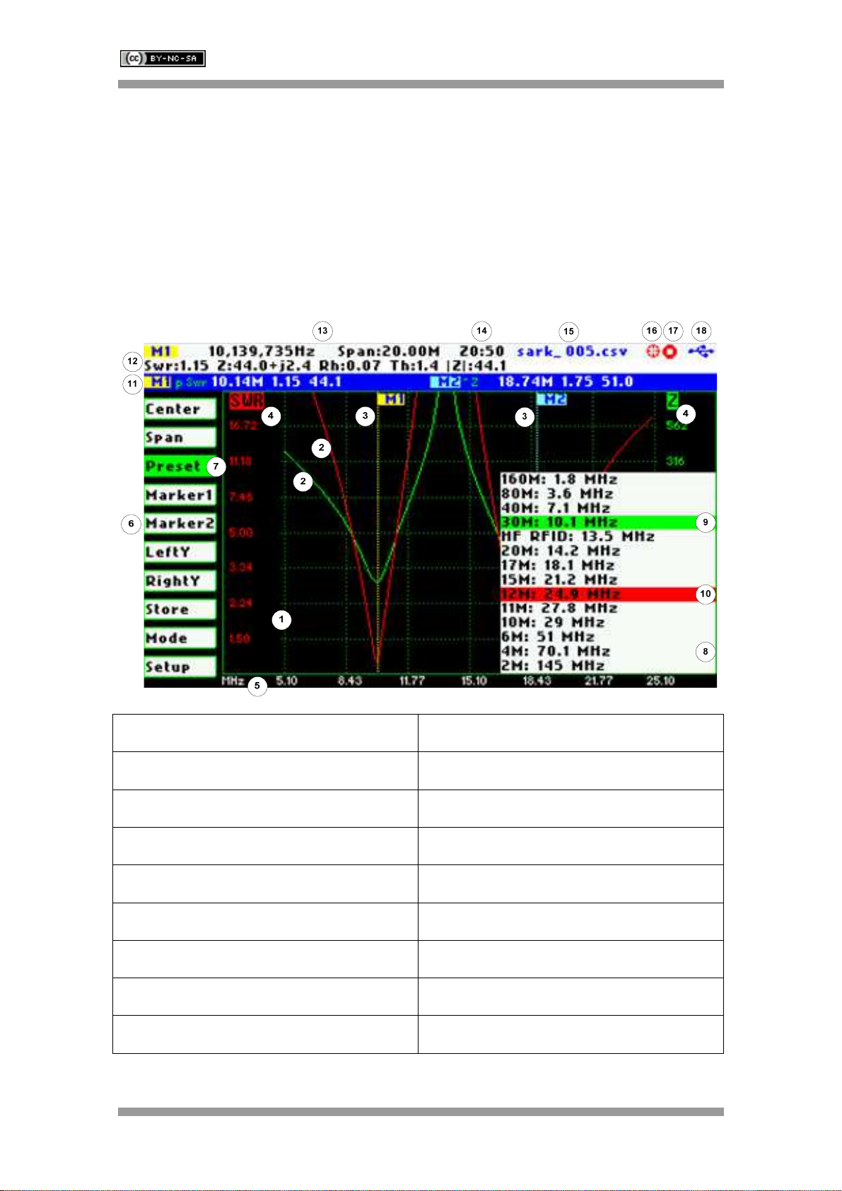
The following figure shows the screen layout in antenna test operating mode. It shows diagram
areas that are the same for all operating modes of the SARK-110. Screen layouts that show
specifics for each operating mode are provided in the corresponding sections of this manual.
1 Diagram 10 Currently selected submenu option
2 Traces 11 Markers information
3 Markers 12 Detailed measurements
4 Vertical axis labelling 13 Frequency and span settings
5 Horizontal axis labelling 14 Reference impedance setting
6 Main menu 15 Loaded impedance data file name
7 Active menu option 16 Calibration status
8 Submenu 17 Run/Hold status
9 Active submenu option 18 USB/Battery status
SARK
SARKSARK
SARK-
--
-110
110110
110
User’s Manual
Rev 0.7 Sept 3
rd
, 2012 - 6 - © Melchor Varela – EA4FRB 2011-2012
3.2 Means of Input
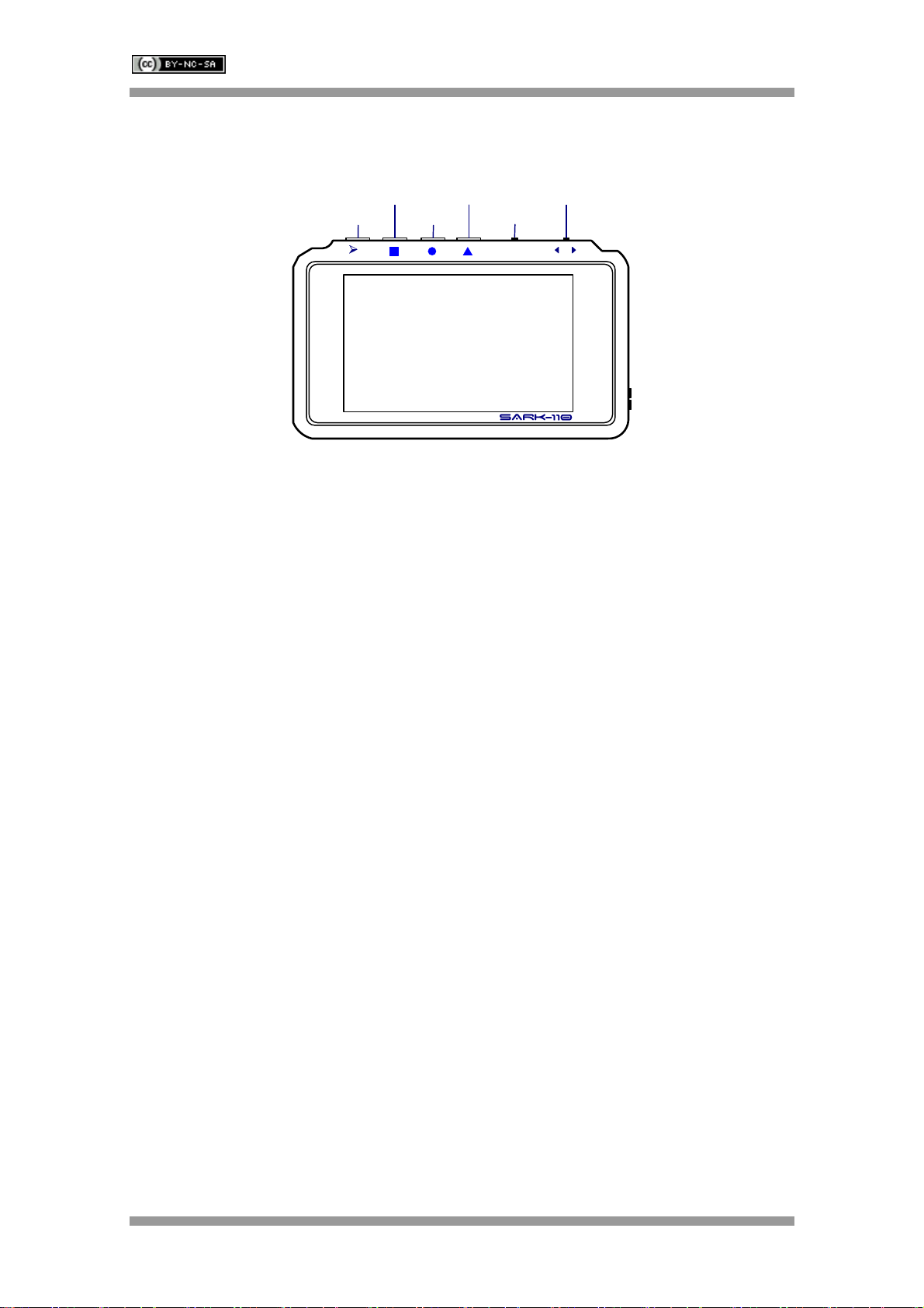
There are four buttons and two navigation keys in the SARK-110.
Navigator A
Navigator B
Run/Hold
Select
Save Screen
Save Conf.
•••
-•••+
||
Navigator A
The Navigator A is used to navigate in the main menu (left side of the screen). The active option
is highlighted with a background green color.
Navigator B
The Navigator B is used for changing the value in the active option of the main menu (for
Center, Span, Marker1, Marker2, LeftY and RightY) and to navigate in the pop-up submenus.
Run/Hold [►||]
The button Run/Hold is used to control the operation state of the SARK-110: Working or Pause.
In the pause state the signal generator and measurement circuits are disabled.
Note: when loading a stored data file the analyzer is placed in pause state
automatically.
Select [■]
The button Select is used to activate the pop-up submenu associated to the active option and for
selecting the desired option of the pop-up submenu.
Note: the selection can be cancelled by pressing any other button.
Save Screen [●]
The button Save Screen is used to take a screenshot of the current screen. The screenshot is
stored in the internal flash disk.
Save Conf. [▲]
The button Save Conf. is used to store the complete analyzer state and settings. The stored
state is recovered automatically after powering on the unit.
SARK
SARKSARK
SARK-
--
-110
110110
110
User’s Manual
Rev 0.7 Sept 3
rd
, 2012 - 7 - © Melchor Varela – EA4FRB 2011-2012
3.3 Changing the Center Frequency
The center frequency adjustment is provided by the «Center» menu option of the main menu.
There are two methods for setting the frequency, either by pressing the button Select [■] to
activate the frequency edit dialog or by using the Navigator B.
The pop-up frequency edit dialog is activated by pressing the button Select [■] when the
«Center» option is active. The frequency is changed by using the Navigator B according the
current frequency multiplier position which is shown in reverse video. The frequency multiplier
position can be changed using the Navigator A. The frequency is validated by pressing the
button Select [■]. The setting could be cancelled by pressing any other button.
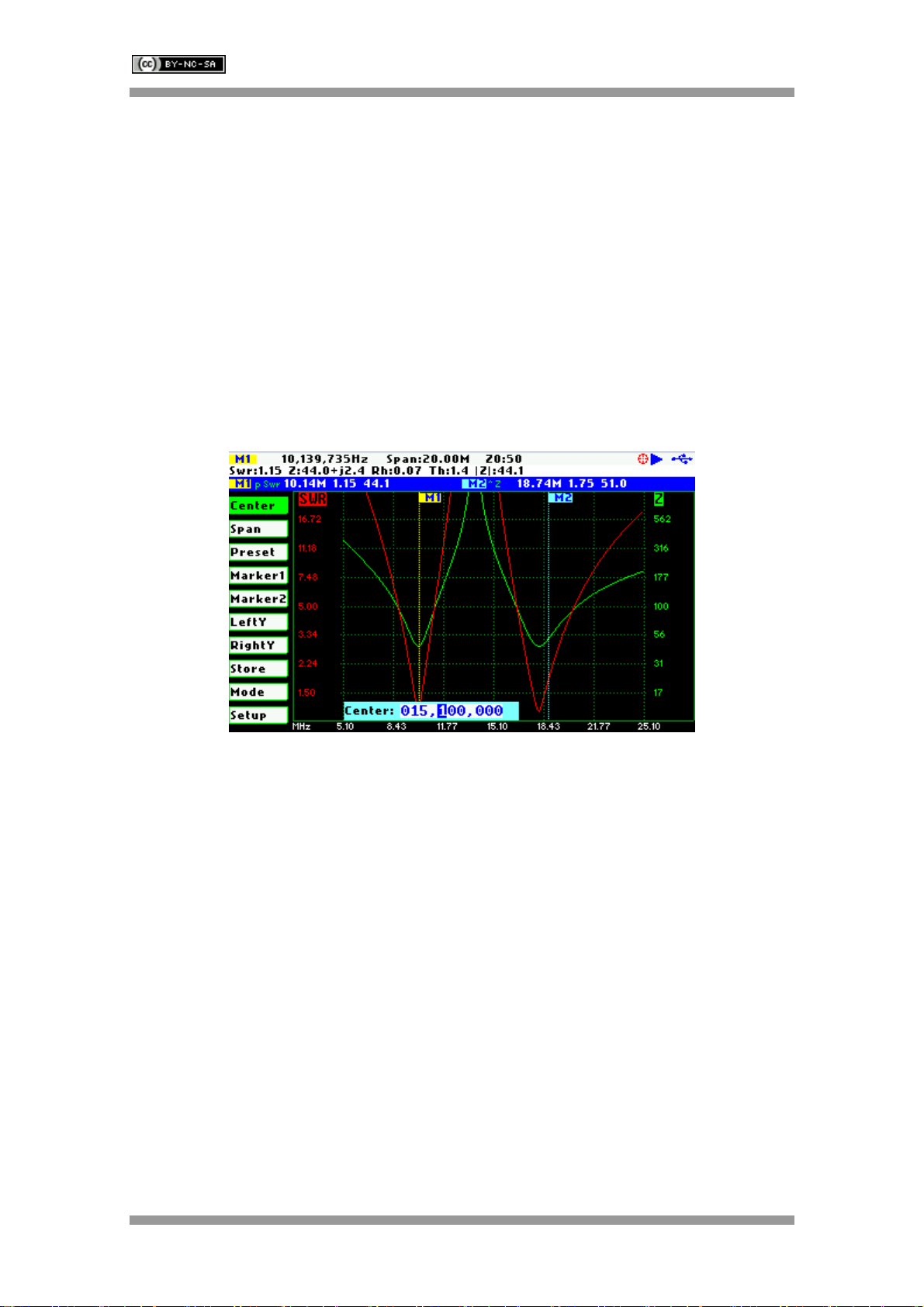
The screenshot below shows the frequency edit dialog showing the frequency multiplier position
in digit 6 (frequency increments of 100 KHz).
The second method for changing the frequency is simply by using the Navigator B when the
Center option is active. The frequency will change according the current frequency multiplier.
The frequency multiplier can be changed from the pop-up frequency edit dialog.
Note: the span range will be automatically adjusted in case the resultant upper or
lower frequency is outside the operating limits
3.4 Changing the Span
The span frequency adjustment is provided by the «Span» menu option of the main menu.
There are two methods for setting the span, either by pressing the button Select [■] to activate
the span edit dialog or by using the Navigator B.
The pop-up span edit dialog is activated by pressing the button Select [■] when the «Span»
option is active. The span is changed by using the Navigator B according the current span
frequency multiplier position which is shown in reverse video. The span frequency multiplier
position can be changed using the Navigator A. The span is validated by pressing the button
Select [■].The setting could be cancelled by pressing any other button.

SARK
SARKSARK
SARK-
--
-110
110110
110
User’s Manual
Rev 0.7 Sept 3
rd
, 2012 - 8 - © Melchor Varela – EA4FRB 2011-2012
The screenshot below shows the span edit dialog showing the frequency multiplier position in
digit 7 (so set to 1 MHz).
The second method for changing the span is simply by using the Navigator B when the «Span»
option is active. The span will change according the current span frequency multiplier. The span
frequency multiplier can be changed from the pop-up span edit dialog.
3.5 Frequency Presets
The analyzer provides predetermined center frequency and span settings for the radio amateur
bands. The frequency presets pop-up list box is activated by pressing the button Select [■] when
the «Preset» option is active; see screenshot below:
The Navigator B is used to navigate the desired option. The selection is validated by pressing
the button Select [■]. Pressing any other button will cancel the setting.
SARK
SARKSARK
SARK-
--
-110
110110
110
User’s Manual
Rev 0.7 Sept 3
rd
, 2012 - 9 - © Melchor Varela – EA4FRB 2011-2012
3.6 Using Markers
The SARK-110 has two markers that can be either manually positioned by the user or operate in
an automatic tracking mode. The markers indicate the horizontal and vertical position of the
point they are positioned on. The horizontal position of a marker is shown by a dotted vertical
line which extends from the top to the bottom of the measurement diagram. The markers
information window, in blue background, shows the frequency or distance (in cable test mode)
and the two values corresponding to the plotted values at each of the markers.
The marker cursor position is selected with the Navigator B when the active menu option in the
main menu is «Marker1» or «Marker2».
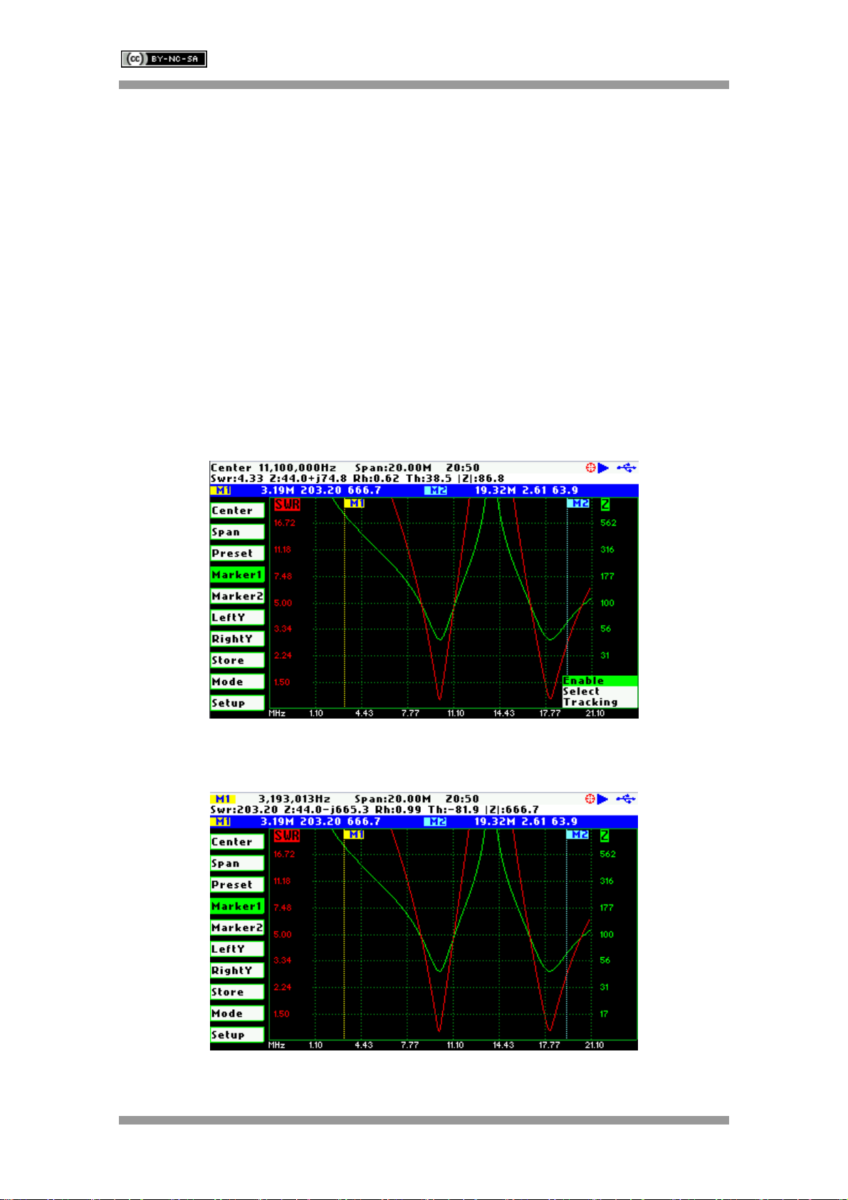
The marker options are accessible in the markers list box which can be activated by pressing
the button Select [■]. Available options are: «Enable» for activating or deactivating the marker,
«Select» for selecting or deselecting the marker, and «Tracking» for selecting the tracking
mode; see screenshot below:
The «Select» option activates or deactivates the display of the detailed parameters at the
marker position. The screenshot below shows the Marker1 in select state:

SARK
SARKSARK
SARK-
--
-110
110110
110
User’s Manual
Rev 0.7 Sept 3
rd
, 2012 - 10 - © Melchor Varela – EA4FRB 2011-2012
The automatic tracking feature makes the positioning of the markers easier so helping the user
to speed-up the measurements.
The following tracking modes are available:
•Peak Min (p)
•Peak Max (P)
•Absolute Min (m)
•Absolute Max (M)
•Value Cross Any (X)
•Value Cross Up (^)
•Value Cross Down (v)
The automatic positioning of markers is activated the «Tracking» sub-option. Then it should be
selected the tracking mode from any of the modes above and after that the applicable parameter
to track. In addition, for the Cross detection modes the detection value shall be specified.
As for example, you could set the Marker 1 to automatically track the minimum SWR values in
the trace: «Marker1» «Tracking» «Peak Min» «SWR»; and the Marker 2 to track the crosses on
the 50-ohm impedance value: «Marker2» «Tracking» «Cross Any»«Z» «50.0».
Or you could program the unit to detect the bandwidth by setting «Marker1» «Tracking» «Cross
Down» «SWR» «2.0»; and «Marker2» «Tracking» «Cross Up»«SWR» «2.0».
The Navigator B will be used to move to the different detection points, except for the Max and
Min tracking modes where logically there is a single detection point.
The tracking mode for each marker is shown in the markers information window. This
information will be shown in red if either the data is not available or if it can not be resolved the
tracking condition; otherwise will be shown in green.
SARK
SARKSARK
SARK-
--
-110
110110
110
User’s Manual
Rev 0.7 Sept 3
rd
, 2012 - 11 - © Melchor Varela – EA4FRB 2011-2012
The screenshot below shows the Marker1 tracking the minimum peaks of SWR and the cross-
up of Z at 50-ohm:
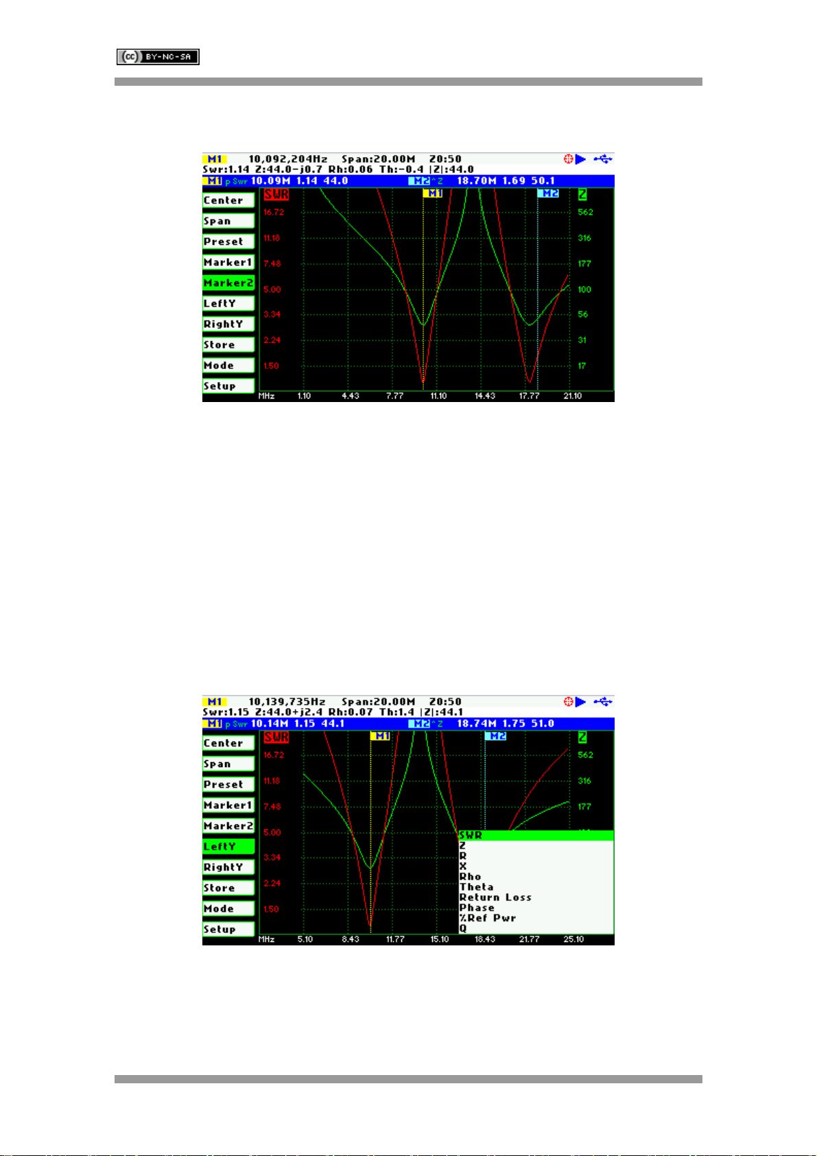
3.7 Changing Vertical Axis Parameter
The SARK-110 in the antenna test mode is able to display two traces from any of the available
parameters for the vertical axis. There are two methods to change the parameter, either by
pressing the button Select [■] to activate the pop-up parameters list box or by using the
Navigator B.
The pop-up parameters list box is activated by pressing the button Select [■] when either the
«LeftY» or the «RightY» option is active. The parameter is changed by using the Navigator B
and the selection is validated by pressing the button Select [■]. Pressing any other button will
cancel the setting.
The screenshot below show the available parameters for the vertical axis:
The second method for changing the either of the vertical axis parameters is simply by using the
Navigator B when either the «LeftY» or the «RightY» option is active. The options will be
selected in sequence.
SARK
SARKSARK
SARK-
--
-110
110110
110
User’s Manual
Rev 0.7 Sept 3
rd
, 2012 - 12 - © Melchor Varela – EA4FRB 2011-2012
3.8 Saving and Recalling Measurements
The SARK-110 has the capability to store the measurements to the internal disk and recall them
either to review the data later in the analyzer screen or to be recovered from the USB disk to be
further analyzed by the ZPLOTS Excel application available at http://www.ac6la.com/zplots.html.
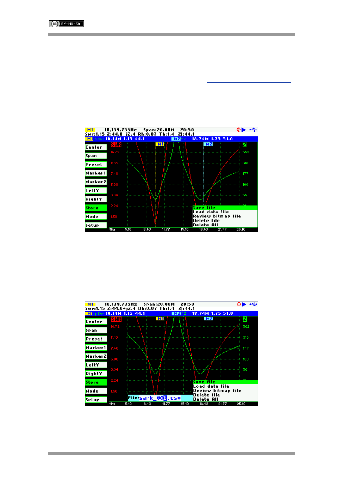
Data file operations are available through the «Store» option of the main menu. A pop-up list
box is activated when pressing the button Select [■] while the «Store» option is active.
The Save File option allows saving the current measured data for further review:
After selecting the «Save File» list box option, the user is prompted for the file name. By default
the file name has the format “sark_xxx.csv”, where xxx is an automatically assigned number.
The user can change the file name by using the Navigator B to change the character value and
the Navigator A to change the character position. Notice that the character position is highlighted
in inverse video. The selection is validated by pressing the button Select [■]. Pressing any other
button will cancel the operation.
To retrieve the stored data it is necessary to select the «Load data file» list box option. A second
pop-up list box will be displayed with the list of the available files. Once the file is selected the
data will be loaded and plotted.

SARK
SARKSARK
SARK-
--
-110
110110
110
User’s Manual
Rev 0.7 Sept 3
rd
, 2012 - 13 - © Melchor Varela – EA4FRB 2011-2012
Files can be deleted by selecting either the «Delete file» or the «Delete All» options. When
selecting the «Delete File» option a pop-up list box will be displayed with the list of available files.
The Navigator B will be used to navigate the files and the button Select [■] to delete the file.
When selecting the «Delete All» option all user files will be deleted. A confirmation dialog box
will be activated to prevent the accidental deletion.
SARK
SARKSARK
SARK-
--
-110
110110
110
User’s Manual
Rev 0.7 Sept 3
rd
, 2012 - 14 - © Melchor Varela – EA4FRB 2011-2012
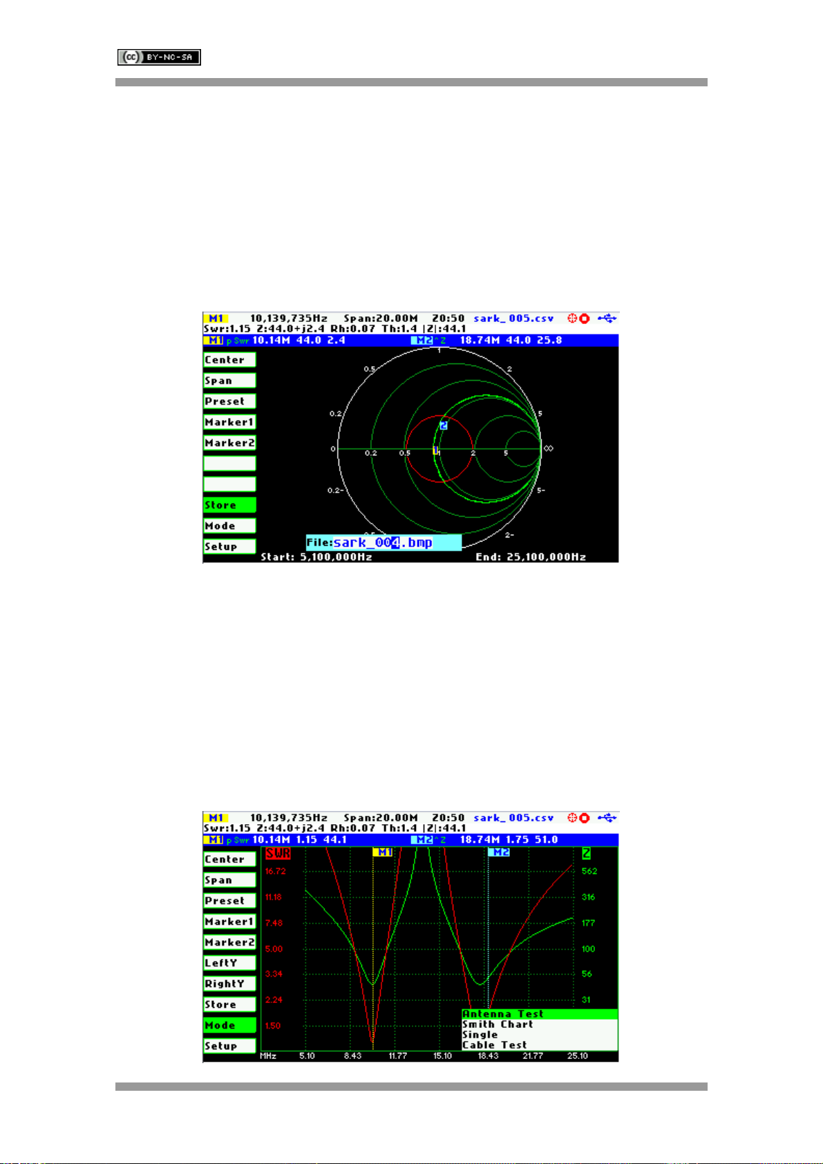
3.9 Taking Screenshots
The current screen can be captured by pressing the button Save Screen [●]. After pressing the
button, the user is prompted for the file name. By default the file name has the format
“sark_xxx.bmp”, where xxx is an automatically assigned number. The user can change the file
name by using the Navigator B to change the character value and the Navigator A to change the
character position. Notice that the character position is highlighted in inverse video. The
selection is validated by pressing the button Select [■]. Pressing any other button will cancel the
operation.
The captured screenshots can be reviewed by selecting the option «Review bitmap file» from
the «Store» menu. Besides they can be reviewed on the PC because they are available in
Windows bitmap compatible format.
Note: the bitmap files use a significant amount of disk (188KB per image)
3.10 Changing the Operating Mode
The analyzer provides different operating modes. The operating mode pop-up list box is
activated by pressing the button Select [■] when the «Mode» option is active; see screenshot
below:

SARK
SARKSARK
SARK-
--
-110
110110
110
User’s Manual
Rev 0.7 Sept 3
rd
, 2012 - 15 - © Melchor Varela – EA4FRB 2011-2012
The Navigator B is used to navigate the mode option. The selection is validated by pressing the
button Select [■]. Pressing any other button will cancel the selection.
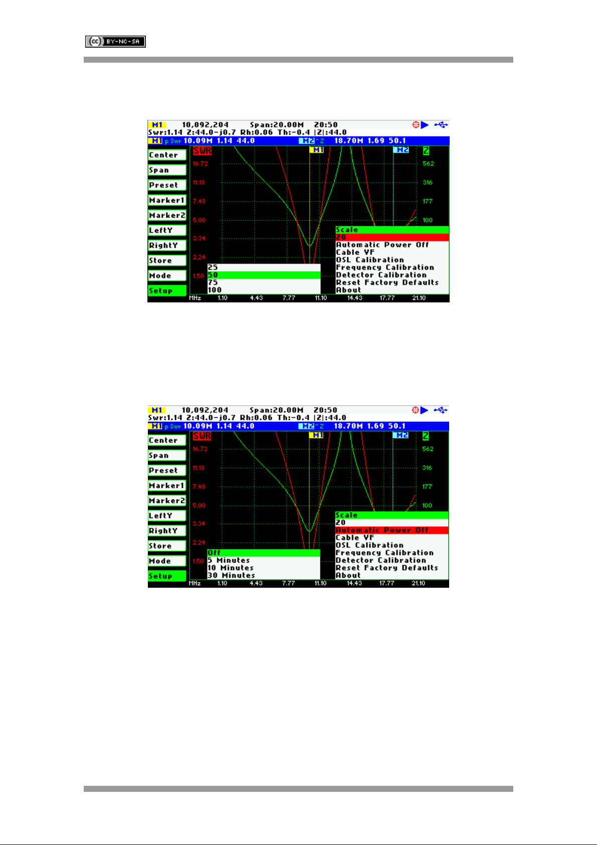
3.11 Changing the Settings
The configuration menu provides access to several setup options of the SARK-110. The setup
pop-up list box is activated by pressing the button Select [■] when the «Setup» option is active;
see screenshot below:
The Navigator B is used to navigate the setup option. The selection is validated by pressing the
button Select [■]. Pressing any other button will cancel the selection.
Setup - Scale
The SARK-110 provides three pre-defined scale values: Normal, High, and Low. This setting
defines the maximum and minimum values for each parameter on the Y axis, see Appendix E:
This configuration affects only to the “Antenna Test” mode.
SARK
SARKSARK
SARK-
--
-110
110110
110
User’s Manual
Rev 0.7 Sept 3
rd
, 2012 - 16 - © Melchor Varela – EA4FRB 2011-2012
Setup - Z0
This setting allows changing the reference characteristic impedance.
Setup - Automatic Power Off
This setting allows programming the automatic power off feature according a set of predefined
values.
After power-off the analyzer operation can be resumed by either pressing the button Select [■]
or powering-off and powering-on using the Power Switch.
SARK
SARKSARK
SARK-
--
-110
110110
110
User’s Manual
Rev 0.7 Sept 3
rd
, 2012 - 17 - © Melchor Varela – EA4FRB 2011-2012
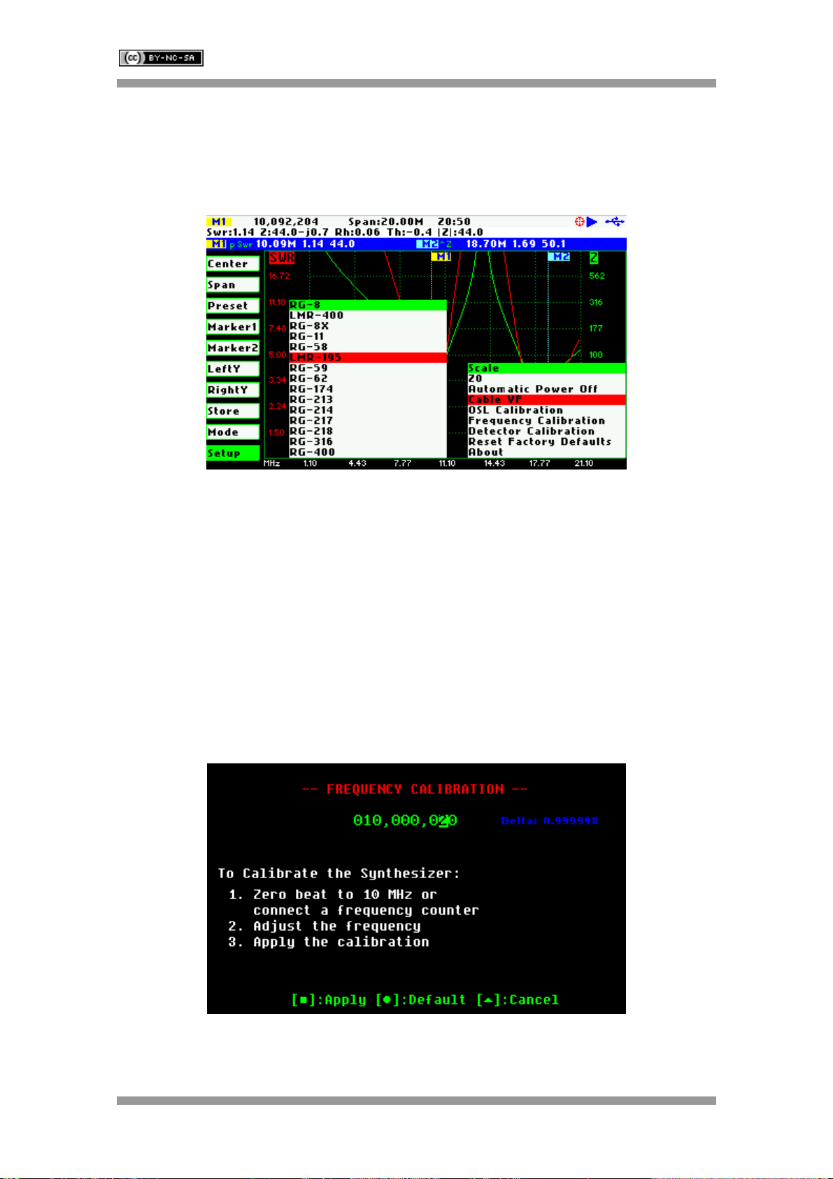
Setup - Cable VF
The length measurements in the cable test mode require the proper setting of the cable velocity
factor. This setup allows the programming of the cable velocity factor from a set of
predeterminated values for popular coaxial cables.
Setup – OSL Calibration
See Appendix C:
Setup – Frequency Calibration
This setup allows the calibration of the frequency synthesizer down to 1 Hz. To calibrate the
synthesizer change the frequency while measuring with an accurate frequency counter or zero-
beating with WWV. When exactly 10 MHz output is obtained, press the button Select [■] to
permanently store the setting.
It will be possible to get back to the default setting by pressing [●].
SARK
SARKSARK
SARK-
--
-110
110110
110
User’s Manual
Rev 0.7 Sept 3
rd
, 2012 - 18 - © Melchor Varela – EA4FRB 2011-2012
Setup – Detector Calibration
See Appendix D:
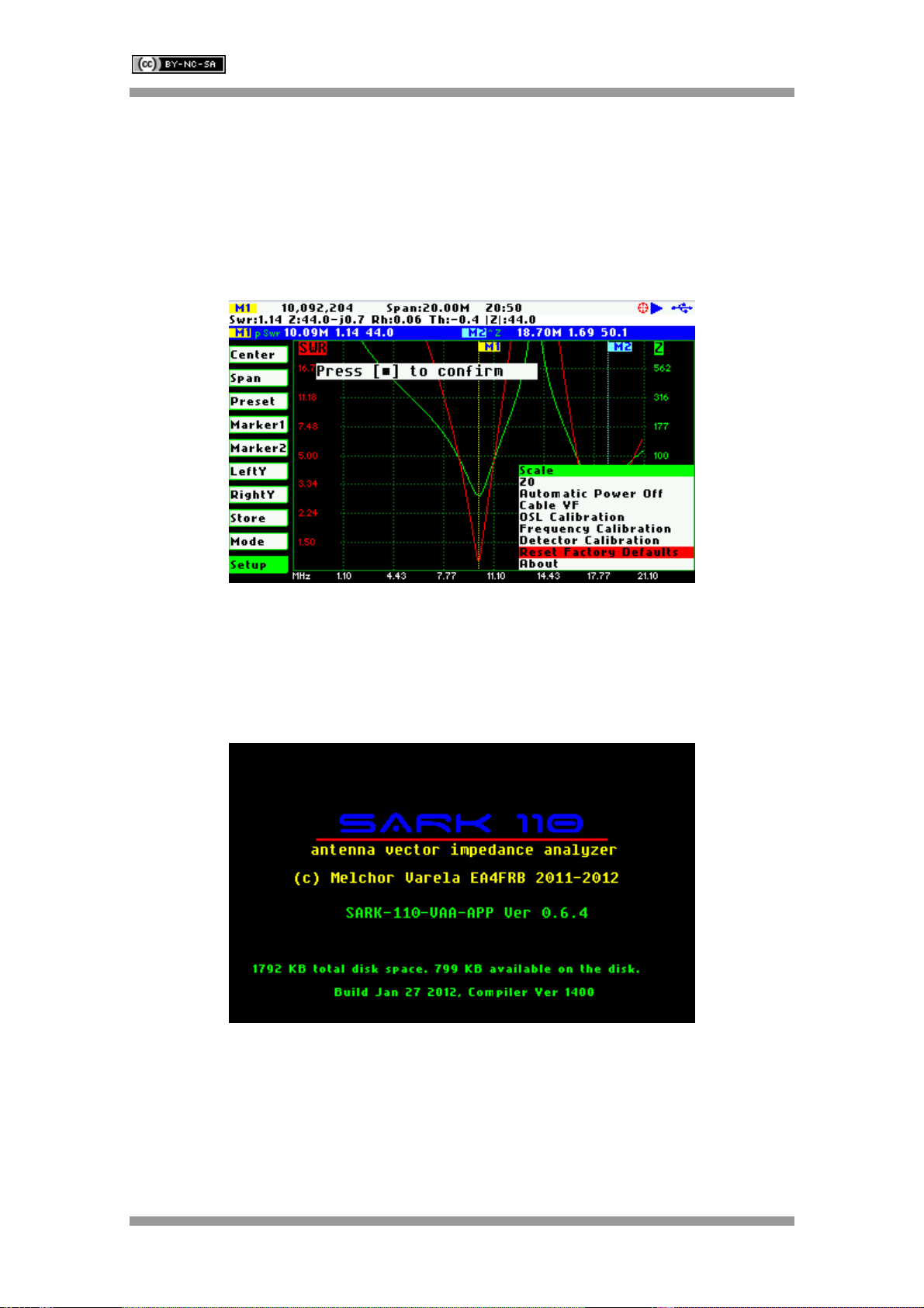
Setup – Reset Factory Defaults
The Reset Factory Defaults options allow resetting the analyzer to the default settings.
Setup - About
The about screen displays copyright information, the release information of the analyzer
firmware and the disk space information.

SARK
SARKSARK
SARK-
--
-110
110110
110
User’s Manual
Rev 0.7 Sept 3
rd
, 2012 - 19 - © Melchor Varela – EA4FRB 2011-2012
4 Antenna Test Mode
2
3
2
7
6
44
5
8
432
9
0
3
1 Diagram 8 Markers information
2 Traces 9 Detailed measurements
3 Markers 10 Frequency and span settings
4 Vertical axis labelling 11 Reference impedance setting
5 Horizontal axis labelling 12 Calibration status
6 Main menu 13 Run/Hold status
7 Active menu option 14 USB/Battery status
The antenna test mode provides the required functionality for the impedance measurements of
antennas, transmission lines, and RF circuits. The analyzer performs the reflection
measurements in a user specified frequency range, defined by the center frequency and the
span, and two user selectable fundamental parameters are displayed in a Cartesian diagram.
Up to two user positionable markers or in automatic tracking mode, are available providing more
information about the ploted points and which are useful for indicating characteristic points in the
plot.
The analyzer performs the measurements and updates the plot continuously, unless it is
stopped by pressing the button Run/Hold [►||]. In this case the results of the measurements are
kept in the internal memory and plotted in the display to allow the user analysis. The

SARK
SARKSARK
SARK-
--
-110
110110
110
User’s Manual
Rev 0.7 Sept 3
rd
, 2012 - 20 - © Melchor Varela – EA4FRB 2011-2012
measurements can be resumed at any moment by pressing again the button Run/Hold [►||].
Measurement data can be stored at any time in the internal disk and restored later for review
through different options in the «Store» menu.
5 Smith Chart Mode
1 Diagram 8 Markers information
2 Trace 9 Detailed measurements
3 Markers 10 Frequency and span settings
4 Constant impedance circle 11 Reference impedance setting
5 Frequency start and end 12 Calibration status
6 Main menu 13 Run/Hold status
7 Active menu option 14 USB/Battery status
The Smith Chart mode is equivalent to the Antenna Test mode but in this case the complex
reflection measurements for the user specified frequency range are displayed in a Smith Chart
diagram. As in the Antenna Test mode, the measurements are performed continuously unless it
is stopped by pressing the button Run/Hold [►||].
Other manuals for SARK-110
1
Table of contents
Other Melchor Varela Measuring Instrument manuals

Popular Measuring Instrument manuals by other brands


PCB Piezotronics
PCB Piezotronics J356A43 Installation and operating manual

Tunix
Tunix EO-250 instruction manual

Coaxial Dynamics
Coaxial Dynamics Web Wattchman instruction manual

MEASUREMENT TECHNOLOGY
MEASUREMENT TECHNOLOGY LCI-90 installation manual

eltherm
eltherm ELAK-RS Operation manual

Hioki
Hioki PW8001-01 instruction manual


