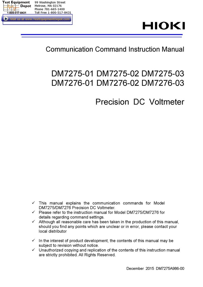
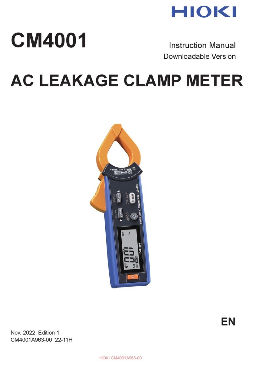
Hioki PW8001-01 User manual

PW8001
Instruction Manual
POWER ANALYZER
EN
Dec. 2021 Edition 1
PW8001A961-00 21-12H
Read carefully before use.
Keep for future reference.
When using the instrument for
the rst time Troubleshooting
Safety Information p. 8 Maintenance and Service p. 231
Measurement Procedure p. 12 Troubleshooting p. 233
Part Names and Functions p. 15 Dialogs p. 236
PW8001-01
PW8001-02
PW8001-03
PW8001-04
PW8001-05
PW8001-06
PW8001-11
PW8001-12
PW8001-13
PW8001-14
PW8001-15
PW8001-16
PW8001 POWER ANLYZER Instruction Manual
www.hioki.com/
*600627740*
HIOKI PW8001A961-00

HIOKI PW8001A961-00

i
Turning the instrument on ........................40
Turning the instrument o.........................40
2.5 Setting Wiring Mode and
Conguring Current Sensor
Settings .................................................41
Wiring mode ............................................42
Current sensor auto-recognition
function ...................................................42
Correcting phase errors for current
sensors ...................................................43
2.6 Simple Conguration (Quick Set)......45
2.7 Zero Adjustment and Degaussing
(Demagnetization)...............................46
2.8 Connecting Measurement Leads
and Sensors to Lines to Be
Measured..............................................47
Wiring diagrams.......................................48
2.9 Checking Connections........................49
3 Displaying Power
Numerically 51
3.1 Displaying Measured Values .............51
3.2 Measuring Power.................................53
Displaying measured power values ..........53
Displaying measured voltage or current
values .....................................................54
Voltage range and current range ..............54
Data refresh interval.................................57
Synchronization source............................58
Low-pass lter (LPF)................................60
Measurement upper frequency limit
and lower frequency limit (conguring
frequency measuring range).....................61
Rectication method ................................62
Scaling (when using VTs [PTs] or CTs)......63
3.3 Integrating Current and Power ..........64
Displaying integrated measured values ....65
Integration mode......................................69
Integration measurement while using
the time control function ...........................70
3.4 Measuring Harmonic...........................71
Displaying measured harmonic values......71
Conguring settings common to
harmonics................................................74
3.5 Measuring Eciency and Loss..........76
Eciency and loss equations ...................76
Displaying eciency and loss...................77
3.6 Motor Measurement
(Motor Analysis-Equipped Model).....78
Motor measurement wiring.......................78
Connection examples of motor analysis....81
Displaying measured motor values...........82
Zero adjustment of motor input.................83
Contents
Introduction........................................................1
Checking Package Contents...........................2
Options (Sold Separately) ...............................3
Symbols and Abbreviations.............................6
Safety Information ............................................8
Precautions for Use..........................................9
Measurement Procedure...............................12
1 Overview 13
1.1 Product Overview ................................13
1.2 Features................................................13
1.3 Part Names and Functions ................15
1.4 Basic Operation
(Screen Display and Layout) .............20
Screen operation .....................................20
Common screen display...........................23
Measurement screen ...............................24
Screen congurations ..............................25
1.5 System Architecture ............................27
1.6 Example Measurement Setups .........28
Measuring eciency of power
conditioners.............................................28
Evaluating the performance of a power
interchange system with a power
conditioner...............................................28
Evaluating conversion eciency of
inverters with built-in SiC..........................29
Analyzing of motors used for vehicles
including EV and HEV..............................29
Evaluating performance of dual inverter
drive systems ..........................................30
Capable of handling special wiring
congurations, such as for measuring
performance of 6-phase motors and for
loss of reactors ........................................30
2 Preparing for
Measurement 31
2.1 Inspecting the Instrument before
Use ........................................................32
2.2 Connecting the Voltage Cords
(Voltage Input)......................................33
2.3 Connecting the Current Sensors
(Current Input)......................................34
Probe 1 terminal ......................................35
Probe 2 terminal ......................................37
If the input exceeds the measurable
range (using VTs and CTs).......................38
2.4 Supplying Power to the
Instrument.............................................39
Connecting the power cord ......................39
PW8001A961-00
HIOKI PW8001A961-00

Contents
ii
Settings which measurement
parameters to save ................................123
Manually saving measured data .............125
Automatically saving measured data ......126
Recordable time and data ......................127
Auto-save operation using time
control ...................................................129
7.4 Saving Waveform Data.....................130
7.5 Saving and Loading
Screenshots .......................................132
7.6 Saving and Loading the Settings
Data.....................................................134
7.7 File and Folder Operation ................135
File and folder operation with a USB
ash drive..............................................135
Formatting the USB ash drive...............136
Manual le transfer
(uploading to an FTP server)..................136
7.8 Measured Value Save Data
Format.................................................137
Header structure....................................137
Status data ............................................140
Data format for measured values............142
7.9 BIN Saving Format............................142
8 Connecting External
Devices 143
8.1 Waveform/Analog Output
(Waveform and D/A Output
Option) ................................................143
Connecting external devices ..................143
Selecting output parameters...................145
Output rates ..........................................148
Examples of D/A output..........................151
8.2 Controlling Integration with
External Signals.................................153
9 Connecting with
computers 157
9.1 Connecting and Setting the LAN
Interface..............................................158
Connecting a LAN cable ........................158
Conguring LAN settings and building
a network environment...........................160
9.2 Remotely Operating the
Instrument through the HTTP
Server..................................................162
Connecting to the HTTP server ..............162
9.3 Acquiring Data through the FTP
Server..................................................164
Conguring the motor input settings .........84
Torque meter correction function ..............89
Measuring the electric angle of the
motor.......................................................91
Detecting the motor’s direction of
rotation....................................................93
4 Displaying Waveforms 95
4.1 Waveform Display Method .................95
4.2 Changing the Waveform Display
and Conguring Recording ................97
Time axis setting......................................97
Vertical axis zoom factor and display
position settings.......................................99
Vertical axis zoom list display .................100
Conguring the trigger settings...............100
4.3 Recording Waveforms ......................102
5 Various Functions 103
5.1 Time Control Function.......................103
Timer control .........................................103
Real time control....................................103
Time control function setting method ......104
5.2 Average Function ..............................105
Average settings....................................105
Average operation .................................106
Behavior when an overload condition
occurs ...................................................106
5.3 Hold Function.....................................107
Operation in the hold state .....................108
5.4 Peak Hold Function...........................109
Operation in the peak hold state.............110
5.5 Delta Conversion Function............... 111
Δ–Y conversion...................................... 111
Y–Δconversion......................................112
5.6 Power Calculation Method ...............113
6 System Settings 115
6.1 Checking and Changing Settings....115
6.2 Initializing the Instrument..................117
System reset .........................................117
Boot key reset .......................................117
6.3 Factory Default Settings...................118
7 Saving Data and
Managing Files 119
7.1 USB Flash Drive................................119
7.2 File Operation Screen.......................121
7.3 Saving Measured Data .....................123
HIOKI PW8001A961-00

Contents
iii
10.5 Specications of Equations..............212
Equations for basic measurement
items .....................................................212
Equations for motor analysis option........216
Equations for harmonic measurement
items .....................................................217
Equations for integration
measurement ........................................219
10.6 U7001 2.5MS/s Input Unit ................220
Input specications ................................220
Accuracy specications..........................222
10.7 U7005 15MS/s Input Unit .................225
Input specications ................................225
Accuracy specications..........................226
Specially specied combinatorial
accuracy with optional products for
current measurement.............................227
11 Maintenance and
Service 231
11.1 Repairs, Inspections, and
Cleaning..............................................231
Calibration .............................................231
Replaceable parts and service life ..........232
Cleaning................................................232
11.2 Troubleshooting .................................233
11.3 Dialogs ................................................236
11.4 Frequently Asked Questions............239
11.5 Calculation of the Combinatorial
Accuracy .............................................240
11.6 External View .....................................241
11.7 Rackmount Fittings ...........................242
11.8 About Technical Information.............245
11.9 Block Diagram....................................246
11.10 Disposal of the Instrument
(How to Remove the Lithium
Battery) ...............................................247
11.11 Open-Source Software .....................248
Index 249
Warranty Certicate
Accessing the instrument’s FTP
server....................................................165
Performing le operation in the FTP
server....................................................166
9.4 Sending Data Using the FTP
Client Function...................................168
Setting automatic le upload ..................168
Uploading les manually ........................172
9.5 Controlling the Instrument with
Communications Commands ..........172
9.6 Connecting and Setting the
GP-IB...................................................173
Connecting the GP-IB cable...................173
Setting the GP-IB address......................174
Resetting the remote control ..................174
9.7 Connecting and Setting the
RS-232C .............................................175
Connecting the RS-232C cable ..............175
Specications ........................................177
Setting the communications speed .........178
9.8 GENNECT One
(PC Application Software) ................179
Installation .............................................179
10 Specications 181
10.1 General Specications......................181
10.2 Specications of Input, Output,
and Measurement .............................182
Basic specications ...............................182
Accuracy specications..........................186
Specications of waveform recording .....187
Specications of motor analysis
(optional) ...............................................188
Specications of waveform and D/A
output (optional).....................................192
Display specications.............................193
Specications of operating part ..............193
External interface specications .............194
10.3 Functional Specications..................195
Auto-ranging..........................................195
Time control...........................................195
Hold function .........................................196
Calculation function ...............................197
Display function .....................................199
Automatic data-saving function...............200
Manual data-saving function...................201
Other functions ......................................202
10.4 Detailed Specications of
Measurement Parameters................203
Basic measurement items ......................203
Harmonic measurement items................208
Power range conguration .....................209
HIOKI PW8001A961-00

Contents
iv
HIOKI PW8001A961-00

1
Introduction
Introduction
Thank you for choosing the Hioki PW8001 Power Analyzer. To ensure your ability to get the most
out of this instrument over the long term, please read this manual carefully and keep it available for
future reference.
The latest edition of the instruction manual
The contents of this manual are subject to change, for example as a result of product
improvements or changes to specications.
The latest edition can be downloaded from Hioki’s website.
https://www.hioki.com/global/support/download/
Refer to the following instruction manuals in accordance with your application.
Name of the instruction
manual Description Format
Operating Precautions
Information for using the instrument safely.
Please review the separate “Operating
Precautions” before using the instrument.
Hard copy
Instruction Manual
(this manual)
Includes basic operation methods,
specications, function descriptions, and
related topics for the instrument.
Hard copy,
PDF le (for web download)
Communications Command
Instruction Manual
Includes information about the
communications commands used to control
the instrument.
PDF le (for web download)
GENNECT One
User’s manual
Includes information about how to install
and use the PC application, as well as its
operation methods, specications, and
related topics.
PDF le (included on CD,
for web download)
Target audience
This manual has been written for use by individuals who use the product or provide information
about how to use the product. In explaining how to use the product, it assumes electrical knowledge
(equivalent of the knowledge possessed by a graduate of an electrical program at a technical high
school).
Trademarks
Windows and Microsoft Edge are either registered trademarks or trademarks of Microsoft
Corporation in the United States and other countries.
HIOKI PW8001A961-00

2
Checking Package Contents
When you receive the instrument, inspect it to ensure that no damage occurred during shipment.
Pay particular attention to included accessories, panel keys and switches, and terminals. If you
nd any damage or discover that the instrument does not perform as indicated in its specications,
please contact your authorized Hioki distributor or reseller.
Conrm the package contents.
PW8001 Power Analyzer
Right side
Model name
: Function available. –: Function not available.
Product name
(order code)
Optional feature (additional function)
Motor analysis Waveform and D/A
output
CAN/CAN FD
interface Optical link interface
PW8001-01 – – – –
PW8001-02 – – –
PW8001-03 – – –
PW8001-04 – – –
PW8001-05 – –
PW8001-06 – –
PW8001-11 –––
PW8001-12 – –
PW8001-13 ––
PW8001-14 – –
PW8001-15 –
PW8001-16 –
The models listed above are equipped with the U7001 2.5MS/s Input Unit and the U7005 15MS/s Input Unit.
The instrument with the rmware version 2.00 installed is going to support the CAN/CAN FD interface and
optical link.
Accessories
Power cord
Operating Precautions (0990A903)
Instruction Manual (this manual)
GENNECT One (PC application) CD
D-sub 25-pin connector (PW8001-02, PW8001-05, PW8001-12, and PW8001-15 only)
HIOKI PW8001A961-00

3
Options (Sold Separately)
The options listed below are available for the instrument. To order an option, please contact your
authorized Hioki distributor or reseller. Options are subject to change. Check Hioki’s website for the
latest information.
Factory default options
Input modules
U7001 2.5MS/s Input Unit
U7005 15MS/s Input Unit
Optional products that can be specied with the product model number (PW8001-xx)
Motor analysis option
Waveform and D/A output option (Cannot be installed in combination with the
CAN/CAN FD interface.)
CAN/CAN FD interface option (Cannot be installed in combination with the
Waveform and D/A output option.)
Optical link interface option
Optional products for voltage measurement
Safety banana plugs (ø4 mm) can be connected to the voltage input terminals of the instrument. Prepare
voltage cords appropriate to your applications.
Product name Maximum rated
voltage and current
Cable
length
(approx.)
Remarks
L1025 Voltage Cord CAT II 1500 V DC
1000 V AC, 1 A
CAT III 1000 V, 1 A
3 m Banana plug-banana plug
(red, black ×1 each)
(alligator clips included)
L9438-50 Voltage Cord CAT III 1000 V, 10 A
CAT IV 600 V, 10 A
3 m Banana plug-banana plug
(red, black ×1 each)
(alligator clips included)
L1000 Voltage Cord CAT III 1000 V, 10 A
CAT IV 600 V, 10 A
3 m Banana plug-banana plug
(red, yellow, blue, gray ×1
each;
black ×4)
(alligator clips included)
L9257 Connection Cord CAT III 1000 V, 10 A
CAT IV 600 V, 10 A
1.2 m Banana plug-banana plug
(red and black, ×1 each)
(alligator clips included)
L1021-01 Patch Cord CAT III 1000 V, 10 A
CAT IV 600 V, 10 A
0.5 m For distributing voltage input
Stackable banana plug–
banana plug (red ×1)
L1021-02 Patch Cord CAT III 1000 V, 10 A
CAT IV 600 V, 10 A
0.5 m For distributing voltage input
Banana plug-banana plug
(black ×1)
L9243 Grabber Clip CAT II 1000 V, 1 A – Red, black ×1 each
L4940 Connection Cable Set CAT III 1000 V, 10 A
CAT IV 600 V, 10 A
1.5 m Banana plug-banana plug
(red and black, ×1 each)
(No alligator clips)
L4935 Alligator Clip Set CAT III 1000 V, 10 A
CAT IV 600 V, 10 A
– Red, black ×1 each
HIOKI PW8001A961-00

4
Options (Sold Separately)
Optional products for current measurement
For details, refer to the instruction manual that came with the current sensor.
: Available. –: Not available
Current sensor
type
Auto-
recognition
function
Model name
Maximum
rated
current
(rms)
Frequency
characteristics
Basic accuracy
(amplitude)
Measurable
conductor
diameter
Number of
channels,
approximate
cable length
Operating
temperature
range
Ultra high
accuracy, direct
connection
PW9100A-3
50 A DC to 3.5 MHz ±0.02% rdg
±0.005% f.s.
Measurement
terminals
M6 screw
3 channels
0°C to 40°C
–PW9100-03
PW9100A-4
4 channels
–PW9100-04
Ultra high
accuracy,
pass-through
CT6904A
500 A
DC to 4 MHz ±0.02% rdg
±0.007% f.s.
ø 32 mm
3 m
−10°C to
50°C
–CT6904
CT6904A-1 DC to 2 MHz 10 m
CT6904A-2
800 A
DC to 4 MHz ±0.025% rdg
±0.009% f.s.
3 m
CT6904A-3 DC to 2 MHz 10 m
High accuracy,
pass-through –CT6862-05
50 A
DC to 1 MHz ±0.05% rdg
±0.01% f.s.
ø 24 mm
3 m
−30°C to
85°C
CT6872 DC to 10 MHz ±0.04% rdg
±0.008% f.s.
−40°C to
85°C
CT6872-01 DC to 2 MHz 10 m
–CT6863-05
200 A
DC to 500 kHz ±0.05% rdg
±0.01% f.s. 3 m
−30°C to
85°C
CT6873 DC to 5 MHz
±0.04% rdg
±0.008% f.s.
−40°C to
85°C
CT6873-01 DC to 1 MHz 10 m
CT6875A
500 A
DC to 2 MHz
ø 36 mm
3 m
–CT6875
CT6875A-1
DC to 1.5 MHz
10 m
CT6876A
1000 A
3 m
–CT6876
CT6876A-1 DC to 1.2 MHz 10 m
CT6877A
2000 A
DC to 1 MHz ø 80 mm 3 m
–CT6877
CT6877A-1 DC to 700 kHz 10 m
High accuracy,
clamp
CT6841A
20 A DC to 1 MHz
±0.3% rdg
±0.01% f.s.
ø 20 mm
3 m
–CT6841-05
CT6843A
200 A DC to 500 kHz
–CT6843-05
CT6844A
500 A
DC to 200 kHz
–CT6844-05
CT6845A
DC to 100 kHz
ø 50 mm
–CT6845-05
CT6846A
1000 A DC to 20 kHz
–CT6846-05
General purpose
clamp*
–9272-05 20 A
200 A 1 Hz to 100 kHz ø 46 mm 0°C to 50°C
*: For measuring commercial-power frequency band
HIOKI PW8001A961-00

5
Options (Sold Separately)
Connection cables
Product name
Cable
length
(approx,)
Remarks
L9217 Connection Cord 1.7 m
CAT II 600 V, 0.2 A
CAT III 300 V, 0.2 A
For motor analysis input, insulated BNC
9642 LAN Cable 5 m CAT5e, cross-conversion connector
included
9637 RS-232C Cable
(9 pins-9 pins, 1.8 m) 1.8 m 9 pins-9 pins, cross cable
9151-02 GP-IB Connector Cable 2 m –
9444 Connection Cable 1.5 m For external control
9 pins-to-9 pins, straight cable
L6000 Optical Connection Cable 10 m Equivalent of 50 µm/125 µm multi-mode
ber
9165 Connection Cord 1.5 m For BNC sync
Metallic BNC–to-metallic BNC
9713-01 CAN Cable 2 m One end not terminated
Other optional products
The below-listed products are manufactured on a per-order basis.
Product name
Cable
length
(approx,)
Remarks
C8001 Carrying Case – Hard trunk type
Equipped with casters
Z5300 Rackmount Fittings – EIA-compliant
Z5301 Rackmount Fittings – JIS-compliant
Z5200 BNC Terminal Box –D-sub 25 pins–to-BNC (female)
20-channel conversion box
PW9100A-3 AC/DC Current Box – 3 channels
Rated current: 5 A
PW9100A-4 AC/DC Current Box – 4 channels
Rated current: 5 A
CT6904A-1 AC/DC Current Sensor 10 m 500 A rated output cable
CT6904A-2 AC/DC Current Sensor 3 m 800 A rated output cable
CT6904A-3 AC/DC Current Sensor 10 m 800 A rated output cable
L3000 D/A Output Cable 2.5 m D-sub 25 pins–to-BNC (male)
20-channel conversion cable
HIOKI PW8001A961-00

6
Symbols and Abbreviations
Safety
In this manual, the risk seriousness and the hazard levels are classied as follows.
DANGER Indicates an imminently hazardous situation that, if not avoided, will result in
serious injury or death.
WARNING Indicates a potentially hazardous situation that, if not avoided, could result in
serious injury or death.
CAUTION Indicates a potentially hazardous situation that, if not avoided, could result in
minor or moderate injury.
NOTICE Indicates potential risks of damage to the supported product (or to other
property).
IMPORTANT Indicates information or content that is particularly important from the standpoint
of operating or maintaining the instrument.
Indicates a high-voltage hazard.
Failure to verify safety or improper handling of the instrument could lead to an
electric shock, burn, or death.
Indicates an action that must not be performed.
Indicates an action that must be performed.
Symbols on the product
Indicates the presence of a potential hazard. For more information about locations where
this symbol appears on instrument components, see “Precautions for Use” (p. 9) and
warning messages listed at the beginning of operating instructions. In addition, see the
accompanying document entitled “Operating Precautions.”
Indicates the power push-button switch that toggles the instrument between on and o.
Indicates a grounding terminal.
Indicates direct current (DC).
Indicates alternating current (AC).
Symbols for various standards
Indicates that the product is subject to the Waste Electrical and Electronic Equipment
(WEEE) Directive in EU member nations. Dispose of the product in accordance with local
regulations.
Indicates that the product complies with standards imposed by EU directives.
HIOKI PW8001A961-00

7
Symbols and Abbreviations
Others
Indicates useful advice concerning instrument performance and operation.
*Indicates additional information is provided below.
(p. ) Indicates the page number to refer to.
START
(Bold letters) Indicates the names of the control keys.
[ ] Indicates the names of user interface elements on the screen.
Windows Unless otherwise noted, the term Windows is used generically to refer to Windows 10.
Current sensor Sensors for measuring currents are collectively referred to as current sensors.
S/s
For this product, the number of times the analog input signal is digitized is indicated in
samples per second (S/s).
Example: 20 MS/s (20 megasamples per second) signies 20×106samples per
second.
Accuracy labeling
The instrument accuracy is expressed by dening a percentage of the reading, a percentage of the
range, a percentage of the full scale, a percentage of the setting, or a limit value for errors in terms
of digits.
% of reading
Reading (display value)
Indicates the value displayed by the instrument.
Limit values for reading errors are expressed as a percentage of the reading (“% rdg”).
% of range
Range
Indicates the measurement range of the instrument.
Limit values for range errors are expressed as a percentage of the range (“% rng”).
f.s.
Full scale (rated current)
For this instrument, this mainly indicates the rated current of the current sensor.
Limit values for full-scale errors are expressed as a percentage of the full scale (“% f.s.”).
digits
Digit (resolution)
Indicates the minimum display unit (in other words, the smallest digit that can have a
value of 1) for a digital measuring instrument.
Limit values for digit errors are expressed using digits.
HIOKI PW8001A961-00

8
Safety Information
Safety Information
Please review the safety information below before using the instrument. Read this manual carefully
and ensure you understand its contents before using the instrument. Improper use of the instrument
could result in serious bodily injury or damage to the instrument.
Measurement categories
IEC 61010 denes measurement categories to facilitate safe use of measuring instruments. Test
and measurement circuits designed to be connected to a main power supply circuit are classied
into three categories depending on the type of main power supply circuit. A measuring instrument
that does not have a measurement category cannot be used to measure a main power supply
circuit.
DANGER
Do not use a measuring instrument to measure a main power supply
circuit whose category exceeds the instrument’s rated measurement
category.
Do not use a measuring instrument that does not have a rated
measurement category to measure a main power supply circuit.
Doing so may result in serious bodily injury or damage to the instrument or other
equipment.
No measurement
category
(O)
Applicable to the measurement of other circuits that are not directly connected to the
main power supply.
EXAMPLE: Measurement on the secondary-side equipment from the socket outlet of
xed installation through a transformer, etc.
Measurement
category II
(CAT II)
Applicable to test and measuring circuits connected directly to utilization points (socket
outlets and similar points) of a low-voltage MAINS installation.
EXAMPLE: Measurements on household appliances, portable tools, and similar
equipment, and on the consumer side only of socket outlets in the xed
installation.
Measurement
category III
(CAT III)
Applicable to test and measuring circuits connected to the distribution part of the a
building’s low-voltage MAINS installation.
Example: Measurements on distribution boards (including secondary meters),
photovoltaic panels, circuit breakers, wiring, including cables, bus-bars,
junction boxes, switches, and socket outlets in a xed installation, as well as
equipment for industrial use and some other equipment such as stationary
motors with permanent connection to the xed installation.
Measurement
category IV
(CAT IV)
Applicable to test and measuring circuits connected at the source of the a building’s low-
voltage MAINS installation.
Example: Measurements on devices installed before the main fuse or circuit breaker in
the building installation.
Outlet
CAT II
Interior wiring
Distribution panel
Service entrance
Service drop
CAT IV
Power meter
CAT III
Fixed equipment
HIOKI PW8001A961-00

9
Precautions for Use
Precautions for Use
Be sure to follow the precautions listed below in order to use the instrument safely and in a manner
that allows it to function eectively.
Use of the instrument should conform not only to its specications, but also to the specications of
all accessories, options, and other equipment in use.
Installing the instrument
WARNING
Do not install the instrument in locations such as the following:
• In locations where it would be subject to direct sunlight or high temperatures
• In locations where it would be exposed to corrosive or explosive gases
• In locations where it would be exposed to powerful electromagnetic radiation or close
to objects carrying an electric charge
• In locations close to inductive heating devices (high-frequency inductive heating
devices, IH cooktops, etc.)
• In locations characterized by a large amount of mechanical vibration
• In locations where it would be exposed to water, oil, chemicals, or solvents
• In locations where it would be exposed to high humidity or condensation
• In locations with an excessive amount of dust
Doing so could damage the instrument or cause it to malfunction, resulting in bodily
injury.
CAUTION
Do not place the instrument on an unstable stand or angled surface.
Doing so could cause the instrument to fall or overturn, resulting in bodily injury or
damage to the instrument.
• Leave at least 30 mm of space on every surface other than the underside to keep the instrument’s
temperature from rising.
• Leave at least 15 mm of space underneath the installation surface (the height of its feet).
• Place with its bottom side facing downward.
• Do not block vent openings.
30 mm or longer30 mm or longer
HIOKI PW8001A961-00

10
Precautions for Use
Handling the instrument
DANGER
Never remove the top cover.
The internal components of the instrument carry high voltages and may become very
hot during operation. Touching them could cause burns or electric shock.
WARNING
Do not use cables whose insulation is damaged or whose metal portion
is exposed.
Doing so could result in serious bodily injury.
If smoke, abnormal sounds, strange odor, or other abnormalities occur,
immediately turn o the instrument, unplug the power cord from the
outlet, and remove measurement leads and sensors.
Failure to do so could result in serious bodily injury or re.
See “11.2 Troubleshooting” (p. 233) and “11.3 Dialogs” (p. 236) before contacting
your authorized Hioki distributor or reseller.
NOTICE
Do not route cords between other objects or step on them.
Do not bend or pull on cables where they connect.
Doing so could break cables.
The instrument is classied as a Class A device under the EN 61326 standard. Use of the
instrument in a residential setting such as a neighborhood could interfere with reception of radio
and television broadcasts. If you encounter this issue, take steps as appropriate to address it.
Cautions for measurement
DANGER
Do not use the instrument to measure circuits that exceed the ratings or
specications of the instrument.
Doing so could cause damage to the instrument or overheating, resulting in serious
bodily injury.
See “10.2 Specications of Input, Output, and Measurement” (p. 182), “10.6 U7001
2.5MS/s Input Unit” (p. 220), and “10.7 U7005 15MS/s Input Unit” (p. 225).
WARNING
Do not touch any conducting wire to be measured.
A conducting wire to be measured may be hot. There is a risk of the operator being
burned.
NOTICE
Do not input voltage or current to the input terminal while the instrument is
powered o.
Doing so could damage the instrument.
HIOKI PW8001A961-00

11
Precautions for Use
Cautions for transporting the instrument
CAUTION
Working with at least one other person, shift the product using the left and
right handles.
Follow your company’s safety guidelines (by using anti-slip gloves, safety
boots, etc.).
Failure to do so could result in bodily injury.
NOTICE
Do not subject the instrument to vibration or mechanical shock while
transporting or handling it.
Do not drop the instrument.
Doing so could damage the instrument.
When carrying the instrument, remove the cables and the USB ash drive and hold the handles.
Shipping Precautions
• When shipping the instrument, use the box and packaging materials in which it was originally
shipped. However, do not use the original box and packaging if they are damaged. If you are
unable to use the original box and packaging, contact your authorized Hioki distributor or reseller.
You will be sent a suitable box and packaging material.
• When packing the instrument, disconnect test leads and a USB ash drive.
• When transporting the instrument, exercise care to avoid dropping it or otherwise subjecting it to
rough handling.
Precautions related to disc usage
• Exercise care to keep the recording surface of the disc free of dirt and damage. If you need to
label the disc, for example with text, use a marker with a soft tip.
• Store discs in protective cases. Avoid exposing the disc to direct sunlight, high temperatures, or
high humidity.
• Hioki is not liable for any computer system issues that arise in connection with the use of this
disc.
HIOKI PW8001A961-00

12
Measurement Procedure
The basic measurement procedure with the instrument is as follows.
1
Inspect the instrument before use
“2.1 Inspecting the Instrument before Use” (p. 32)
2
Prepare for measurement
“2.2 Connecting the Voltage Cords (Voltage Input)” (p. 33)
“2.3 Connecting the Current Sensors (Current Input)” (p. 34)
“2.4 Supplying Power to the Instrument” (p. 39)
For high-precision measurement, allow the instrument to warm up for 30 minutes or more after
turning on the instrument before performing the zero adjustment.
3
Set wiring modes and congure current sensor settings
“2.5 Setting Wiring Mode and Conguring Current Sensor Settings” (p. 41)
4
Conguring Simple Setup (Quick Set)
“2.6 Simple Conguration (Quick Set)” (p. 45)
5
Perform the zero adjustment.
“2.7 Zero Adjustment and Degaussing (Demagnetization)” (p. 46)
Always perform zero adjustment before connecting measurement leads and sensors.
6
Connect measurement leads and sensors to lines to be measured.
“2.8 Connecting Measurement Leads and Sensors to Lines to Be Measured” (p. 47)
7
Verify proper connection.
“2.9 Checking Connections” (p. 49)
8
View the measured values and waveforms
“3 Displaying Power Numerically” (p. 51)
“4 Displaying Waveforms” (p. 95)
Starting/stopping
the integration
Displaying
the waveforms
9
Saving data
“7 Saving Data and Managing Files” (p. 119)
10
Analyze the data
“8 Connecting External Devices” (p. 143)
“9.1 Connecting and Setting the LAN Interface” (p. 158)
“9.8 GENNECT One (PC Application Software)” (p. 179)
11
Finish the measurement
HIOKI PW8001A961-00

13
1Overview
1.1 Product Overview
This instrument is a power analyzer that can analyze the power conversion eciency by
simultaneously measuring the input and output powers of an object under measurement. The
instrument can include up to eight input modules and support various lines to be measured
according to your applications by combining wiring congurations from single-phase to three-phase
four-wire congurations as desired.
1.2 Features
Up to eight modules can be included
By combining two types of input modules with one to eight channels as desired, the measurement system
most suitable for your applications can be congured in a single instrument.
Combination of the two types of input modules enables the conguration of the most
suitable system
Two types of input modules are available: a general-purpose input module with high withstand voltage, the
U7001, and an input module with world-class accuracy of ±0.03% and world-class high resolution and high-
speed sampling, the U7005.
According to the performance you need, the two types of input modules can be combined and installed on the
PW8001.
U7001 (p. 220)
Measurement for CAT II at 1500 V is
now possible during the development,
evaluation, and delivery inspection of
power conditioners.
Power measurement basic accuracy
±0.07%
U7005 (p. 225)
Eciency of SiC/GaN inverters and loss
of reactors and transformers can be
measured with high accuracy.
Power measurement basic accuracy
±0.03% (DC accuracy ±0.05%)
Sampling frequency 2.5 MHz 15 MHz
ADC resolution 16-bit 18-bit
Measurement frequency band DC, 0.1 Hz to 1 MHz DC, 0.1 Hz to 5 MHz
Maximum input voltage 1000 V AC, 1500 V DC 1000 V AC, 1000 V DC
Maximum rated line-to-ground
voltage
600 V AC, 1000 V DC CAT III
1000 V AC, 1500 V DC CAT II
600 V CAT III
1000 V CAT II
Automatically recognizes current sensors
(p. 42)
The instrument automatically acquires information on
current sensors connected to itself and corrects their
phase errors.
This signicantly reduces the setting time before
measurement and strongly supports accurate power
measurement.
Automatically
acquiring information
Powered by PW8001
Simple Settings (Quick Set)(p. 45)
The Quick Set function allows measurement conditions to be set to typical values at once according to the
selected lines to be measured.
1 Overview
Overview
HIOKI PW8001A961-00

14
Features
Simultaneously analyzes up to 4 motors with
a single instrument (optional)(p. 78)
A single PW8001 can measure and analyze the torque
and RPM of four motors simultaneously. This feature
is eective for evaluating systems that control wheels
with multiple motors, including electric all-wheel drive
(AWD) vehicles.
Torque
RPM
Torque
RPM
Torque
RPM
Torque
RPM
Torque
RPM
Measurement of up to 32 channels is
supported.
This feature will be supported in rmware version 2.00.
Optical link interface (optional)
By connecting two PW8001 units with an optical cable
(up to 500 m), measured data can be consolidated
in a single PW8001 in real time. The power of a
maximum of 16 channels and 8 motors can be
simultaneously analyzed and their eciency and loss
can be displayed and recorded with a single unit.
BNC synchronous interface
Up to four units (one master unit and three subordinate
units) can be synchronized with each other in data
refresh timing and integration control timing.
Master
Subordinate
Real-time transfer
Optical cable
(Up to 500 m)
Master unit shows all data.
This system aggregates measured data to one unit.
Analysis of 8 motors Analysis of 4 motors
Power measurement of 8 channels
Power measurement of 16 channels
The instrument’s ability to combine with various current sensors is expanding usage
applications from HILS development to the evaluation of actual equipment.
You can select the most suitable current sensor from a lineup covering various measurement applications to
measure current.
High-accuracy clamp type
Clamp-type sensors enable quick and easy connecting
work. Excellent environment performances broaden
the utilization eld from the HILS development to the
evaluation of actual equipment.
High-accuracy pass-through type
Pass-through-type sensors overwhelmingly
outperform others in accuracy, bandwidth, and
stability. Measurement for a wideband of 10 MHz at a
maximum and a large current of 2000 A at a maximum
can help state-of-the-art research and development.
High accuracy, direct connection type
The DCCT method uniquely developed by Hioki
enables world-leading accuracy and bandwidth for the
50 A direct connection type.
Measured data can be integrated into the
existing CAN network with a CAN/CAN FD
bus output (optional)
This feature will be supported in rmware version 2.00.
Measured data can be output as CAN/CAN FD signals
to the CAN bus in real time. By recording the ECU and
measured data on the CAN bus with a data logger,
the data can be integrated without causing a time
shift or degradation of accuracy and a comprehensive
evaluation can be achieved.
CAN analysis system
CAN output
Power measuring CAN bus
Automotive CAN bus
Measuring power uctuation
HIOKI PW8001A961-00
This manual suits for next models
11
Table of contents
Other Hioki Measuring Instrument manuals

Hioki
Hioki PQ3100 User manual

Hioki
Hioki PW3198 User manual

Hioki
Hioki PW3365-20 User manual

Hioki
Hioki lr5001 User manual

Hioki
Hioki HiTester 3443-01 User manual

Hioki
Hioki SM-8213 User manual

Hioki
Hioki 9605-01 User manual

Hioki
Hioki CM3286 User manual

Hioki
Hioki 3441 User manual

Hioki
Hioki PR8111 User manual