Melink Intelli-Hood User manual

Melink Corporation (513) 965-7300 www.melinkcorp.com
INSTALLATION MANUAL
®
Revision 130711

Melink Corporation (513) 965-7300 www.melinkcorp.com
Table of Contents
2
Step Installation Page
1 Install System Controller 4
2 Install Variable Frequency Drive 6
3 Install Touchpad 8
4 Install Temperature Sensor(s) 10
6 Install Hood Controllers 15
8 Install Air Purge Units 21
9 Install Cables 22
10 Setting Addresses 28
Contractor
Electrical
Electrical
Mechanical
Mechanical
Mechanical
Mechanical
Mechanical
Mechanical
5 Install Canopy Sensor Mechanical 13
7 Install Optic Sensors Mechanical 17
11 Install Options (if applicable) Mechanical 29

Melink Corporation (513) 965-7300 www.melinkcorp.com
Tools & Materials Required
Materials Required
●Suitable fasteners for mounting the System Controller and Variable Frequency Drive
(VFD)
▫hollow cinder block (3/16” toggle bolts)
▫concrete or filled cinder block (lead anchors 1/2” dia. with 1/4” x 1-14” lag screws)
▫drywall (3/16” toggle bolts)
▫plywood (#8 X 1-1/4” wood screws)
▫metal back-plate (#8 X 1-1/4” sheet metal screws)
●Conduit and wire for wiring the System Controller and VFDs
Tools Required
●Drill and Drill Bits (Cobalt is best for stainless steel) - bit sizes: 1/8” & 1/4”
●Hole Cutter or Punch for Stainless Steel with cutter sizes: 1-1/2” & 1-1/8”
●Adjustable Pliers and Adjustable Wrench
●Screwdrivers - Straight & Phillips, Large and Small
●Wire Cutter and Wire Stripper
●Measuring Tape and Level
●Step Ladder
Note: All high voltage wiring to be completed by trained service personnel. (Local code
may require a licensed electrician.)
3

Melink Corporation (513) 965-7300 www.melinkcorp.com
Install System Controller
For retrofits, the System
Controller is typically mounted
above the hood. Select a location
that is easily accessible and close
to where the Touchpad will be
mounted. Ideally, you should
secure it to a wall. DO NOT
PENETRATE THE HOOD
EXHAUST PLENUM.
For new construction, the hood
manufacturer typically provides a
utility cabinet in which to mount
the System Controller. If the
hood has a utility cabinet with
extra space, mount the System
Controller (and VFDs) there.
A
4
Select System Controller Location
1

Melink Corporation (513) 965-7300 www.melinkcorp.com
Turn OFF the System Con-
troller power switch before
wiring. Also turn off the
breaker feeding this circuit.
Install System Controller
B
C
Wire Connections Inside System Controller
D Retrofits:
It is not required to use
these output terminals if
there are other provisions
in place to control the
hood lights. Note that
output voltage will be the
same as the input voltage.
Tungston Output Rating:
8A @ 120V
5.4A @ 240V
115/230V
INPUT
L N G L N G
115/230V (15A)
LIGHTS (OUTPUT)
New Construction & Retrofits:
Main Input Power
from Hood Light Circuit
115-230 VAC @ 50/60Hz; 17A Max
New Construction:
Outgoing Power to Hood Lights
Output Voltage Matches Input
15 Amps max
For both New Construction & Ret-
rofits, wire the System Controller
using the hood light circuit. The
circuit must be 115V to 230V, at
50-60Hz. Maximum input current
is 17A.
5
1
Turn Off Power Switch Wire System Controller
ON
OFF
115V or 230V
Wire gauge per NEC; allowable size range is 16AWG to 12AWG.

Melink Corporation (513) 965-7300 www.melinkcorp.com
All wiring must comply with the National Electric Code (NEC
and local code requirements.
Install Variable Frequency Drive
For new construction, the Intelli-Hood includes a Variable Frequency Drive or VFD for each
kitchen exhaust and make-up air fan. This type of starter is for use with 3-phase motors only. It
not only turns the fans on and off, but also varies the speed of the motors by varying the output
frequency and voltage. Therefore, you do not need a conventional magnetic motor starter with
our system. Caution: If you have a tempered make-up air unit, then the control circuit for the
heating system must be fed by a separate power source and NOT from the VFD! The output of
the VFD must be wired to the motor ONLY and NOT to a transformer or any part of a control cir-
cuit!
If there is a make-up air unit, then the VFD for this unit must be interlocked with the fire suppres-
sion micro-switch so that this fan turns off in the event of a fire. This is accomplished by connect-
ing a low-voltage cable between designated terminals on the VFD (01 and 04 for Allen-Bradley)
and the Normally Closed (NC) terminals on the micro-switch. Caution: With variable frequency
drives, there must be a separate conduit run for the output of each VFD (inputs may be run to-
gether if desired). If this is not done, there is a strong probability of problems due to line interfer-
ence and inaccurate motor control.
For retrofits, the only difference between new construction and retrofits is that on retrofits you
will already have conventional magnetic motor starters installed. In most cases, it is
recommended that you install the VFD on the output side of the existing starters. This will enable
the cooks/chefs to use the existing hood fan (and light) switch and not have to change their hab-
its. This will also allow you to keep the existing circuit intact between the magnetic starter for the
make-up air unit and the fire suppression system micro-switch.
6
2
A Verify Variable Frequency Drive Wiring

Melink Corporation (513) 965-7300 www.melinkcorp.com
3-phase
input from
breaker or
magnetic
motor starter
The location must be relatively free of dirt,
grease, and water. The ambient tempera-
ture must be between +14 degrees F and
+122 degrees F. There should be 5” of
clearance on the top and bottom and 1” on
the sides for adequate ventilation/cooling.
Install Variable Frequency Drive
C
1”
5”
5”
1”
E
D
3-Phase
Input 3-Phase
Output
Mount each VFD with appropriate fasteners.
Then install separate conduit for the input
and output power wiring to prevent electrical
interference between the conductors.
L1
L2
L3
U
V
BR+
W
G
BR-
3-phase
output to
fan motor
Remove the VFD top cover and connect
the line voltage wiring to the VFD input
power terminal block as shown above.
Then connect the output power from the
terminal block to the respective fan motor
on the roof. The ground wire must be a
minimum of 14 AWG and as short as pos-
sible. The output wiring for each VFD
MUST be in a separate conduit run.
7
2
For retrofits, each VFD is typically
mounted on the output side of the exist-
ing motor starter, which is often located
in an electrical room, above the hoods,
or inside a utility cabinet. For new con-
struction, the hood manufacturer typi-
cally provides a utility cabinet in which to
mount the VFDs.
Select VFD Location Check VFD Location
Mount VFD Wire VFD
B

Mount the Touchpad to the junction box
and secure the cover plate by snapping it
on.
Plug the connector into the receptacle on
the back of the Touchpad.
C
Melink Corporation (513) 965-7300 www.melinkcorp.com
Before removing the switch
cover plate, turn off the circuit
breaker.
For retrofits, if you want to replace the
existing fan and light switch with our
Touchpad, remove these switches from the
junction box. Then remove the existing
wires to make room for the Touchpad Ca-
ble.
Run the Touchpad Cable inside the exist-
ing conduit and leave approximately 5
inches of slack inside the junction box.
You will connect the other end of the Cable
to the System Controller in Step 9.
B
Install Touchpad
A
D
8
3
Run Touchpad Cable
Plug In Cable Mount Touchpad
Remove Existing Switches
O

Mount the Touchpad to the junction box
and secure the cover plate by snapping it
on.
Plug the connector(s) into the receptacle
on the back of the Touchpad.
C
Melink Corporation (513) 965-7300 www.melinkcorp.com
Run the Touchpad Cable inside the 3/4”
conduit or through the back of the box and
leave approximately 5 inches of slack in-
side the junction box. You will connect the
other end of the Cable to the System Con-
troller in Step 9. If another device will be
installed downstream of the Touchpad, run
two cables.
B
Install Touchpad
A
D
9
3
Run Touchpad Cable
Plug In Cables Mount Touchpad
Install Surface Mount Box
O
Install the Surface Mount box by attaching
screws through the holes provided inside
the box. If possible to bring cable in
through the wall behind the box, first drill a
1” hole in the wall. If not, install 3/4” con-
duit stubbed up above the ceiling for the
cable run.

L ≤24” (600mm)
L ≤24” (600mm)
Melink Corporation (513) 965-7300 www.melinkcorp.com
4
5
Hood 1 (Top View)
Install Exhaust Temperature Sensor
B
Install one (1) Temperature Sensor
per exhaust duct, if the length of the
duct is less than 24”. In most cases
this will mean one Temperature
Sensor per hood.
In some cases, this will mean two
Temperature Sensors per hood.
If the length of the duct is more than
24”, then install two Temperature
Sensors in order to obtain a better
average reading.
A
Duct Top View
L < 24” (600mm)
L ≥24” (600mm)
Hood 2 (Top View)
Hood 3 (Top View)
4
Determine Number of Sensors
Select Location for Mounting Sensor
Select a location for mounting each
Temperature Sensor. The tip of the
sensor should be inside the center
of the duct to sense the average
temperature. For most installations,
proceed with steps C-F on page
10. An alternate mounting proce-
dure is described in steps C-J on
pages 11 and 12.
10

Melink Corporation (513) 965-7300 www.melinkcorp.com
4
5
Probe Protector
Temperature
Probe
Quick-Seal Fitting
Shielded Receptacle
Protective Sleeve
D
F
Mount each Temperature Sensor from the
inside of the duct. Insert the lock washer
and tighten the nut from the outside of the
duct, then re-attach protective sleeve and
strain relief.
1-1/8”
(28.575mm)
Drill or punch a 1-1/8” (28.575mm) diame-
ter hole at the proper location for each
Temperature Sensor.
C
Each Temperature Sensor should be
located as closely to the top of the hood as
possible for easy access and cleaning.
E
11
Install Exhaust Temperature Sensor
4
Select Location on Duct Side View of Sensor
Drill Hole in Duct Mount Sensor

B
Melink Corporation (513) 965-7300 www.melinkcorp.com
4
5
By reaching into the 2-1/4” hole, insert the
stud into the 3/16” hole from inside the
duct so that the threaded end is protruding
outward. Tighten the wing nut onto the
stud until its self-clenching base is securely
wedged into the hole. Repeat this step for
the other studs.
A
C
Place the gasket over the studs, followed
by the flange fitting. Tighten with the (4)
wing nuts using an adjustable wrench
until the unit is secure. Check around
the seal to make sure the flange is sitting
flush to the duct with no gaps.
Remove wing nut from each stud. Check to
be sure that all the studs are securely
wedged into each hold. If any feel loose, re-
tighten the wing nut onto the stud using a
wrench. Remove all remaining wing nuts.
Install Exhaust Temperature Sensor
Insert Studs Tighten Studs
4
Mount Sensor
12

L ≤15’ (4572mm)
Melink Corporation (513) 965-7300 www.melinkcorp.com
4
5
Hood 1 (Top View)
Install Canopy Sensor
B
Install one (1) Temperature Sensor per hood, if the length of the hood is less than 15’. In most
cases this will mean one Temperature Sensor per hood.
A
L < 15’ (4572mm)
Hood 2 (Top View)
5
Determine Number of Sensors
Select Location for Mounting Sensor
Select a location for mounting each
Temperature Sensor. For hoods
<15’, the sensor should be close to
the center of the canopy. Be care-
ful to avoid installing the sensor
next to incandescent light bulbs as
they can adversely affect accuracy
of the sensor. Proceed with steps
C-F on page 14.
13
In some cases, this will mean two Temperature Sensors per hood.
Sensor Location
Sensor Location

Melink Corporation (513) 965-7300 www.melinkcorp.com
D
C
E
F
Install Canopy Sensor
Select Location on Roof of Hood Side View of Sensor
Drill Hole in Roof of Hood Mount Sensor
5
14
Temperature
Probe
Quick-Seal Fitting
Shielded Receptacle
Protective Box
1-1/8”
(28.575mm)
Roof of
Hood
1-1/8”
(28.575mm)
1-1/8”
(28.575mm)
L < 15’ (4572mm)
L ≤15’ (4572mm)
Hood 2 (Top View)
Hood 1 (Top View)

Melink Corporation (513) 965-7300 www.melinkcorp.com
5
3
Install Hood Controllers
B
A
D
C
Select Hood Controller
Location Option 1: Secure Hood
Controller to Standing Seam
Option 2: Secure Hood
Controller to All-Thread Option 3: Secure Hood
Controller By Bolting to Wall
(Remove Clamps)
6
15
Select a location from the following
four options for mounting each Hood
Controller. The best way will vary
based on conditions at each hood.

Melink Corporation (513) 965-7300 www.melinkcorp.com
5
3
Install Hood Controllers
6
16
G
F
E Option 4: Secure Hood
Controller with Pass-Thru
Nipple to APU
Re-Attach Lid of
Hood Controller
Re-Attach Lid of Hood Controller

of the cooking surface and the middle of the
hood filters. The Optic Sensors should be
mounted along that virtual line inside the
ends of the hood. (This is typically about 3”
from where the fitter bank meets the top of
the hood.) Also, the Optic Sensors must be
mounted directly across from each other.
Melink Corporation (513) 965-7300 www.melinkcorp.com
5
3
Install Optic Sensors
B
A
D
C
Make sure there are no obstructions at
least 10” (254mm) from where you need to
penetrate the top of the hood. Also, make
sure the location will not cause the Optic
Sensor beam to be obstructed by anything,
such as fire suppression piping.
To determine
where to install
the Optic Sen-
sors, imagine a
virtual line be-
tween the front
1-1/2”
3-1/4”
Approx. 3”
is typical.
Check Hood Select Sensor Locations
Mark Hole Locations Drill Holes in Hood
7
Then drill or punch a 1-1/2” (38mm) hole at
these same locations.
The hole locations need to be centered 3-1/4”
(83 mm) from the inside ends of the hood.
Drill a small pilot hole to mark these exact
locations.
17

Melink Corporation (513) 965-7300 www.melinkcorp.com
5
3
Nut
Lock Washer
Gasket
Threaded
Coupling
Compression
Nut
Insert the Purge Pipes inside the
Fittings with the notch positioned
above the hood. Tighten the Fitting
temporarily, until the Optic Sensors
are mounted.
F
Above Hood
Inside Hood
E
Install Optic Sensors
7
Install Fittings
Install Purge Pipes
Install the Fittings at the hood
penetrations in the order shown.
Provided UL Listed fittings must
be used.
18

5
3
Approx. 3”
is typical.
H
Disengage the cover from the base on each
Optic Sensor. One has a circuit board
labeled ‘Emitter’, and the other is labeled
‘Receiver’.
Melink Corporation (513) 965-7300 www.melinkcorp.com
Use the base of each Optic Sensor as a
template to mark the location for two
mounting holes. Be sure to locate the
Optic Sensor in the virtual line mentioned
in step 5-B. Drill 3/16” holes.
Mount the base with two stainless
steel screws. The screws can be
located inside or outside of the
hood, depending upon the
location of the hood. If the hood is
located against a wall, then self-
tapping screws from the inside
must be used. If the hood is not
located against a wall, then use
the machine screws, washers and
nuts provided.
19
Install Optic Sensors (Optic Enclosures)
Base
Disengage Optic Sensors
7
Mount Optic
Sensor Base
Mark Hole Locations
J
Cover
G

Melink Corporation (513) 965-7300 www.melinkcorp.com
Emitter
Install Optic Sensors
L
Install Optic Cables
Run the cables up each Purge
Pipe and verify that they are
located inside the notches
before installing the APUs.
Run Cable Up Purge Pipes
7
K
Remove the Optic Cables from the box. Insert the end of one cable with the small anti-
snag boot up through the purge pipe from the optic housing with the Emitter Board. Plug in the
cable end with the round connector and push any excess slack up the purge pipe. Mount the
cover onto the base. Repeat with Receiver Board.
Receiver
20
Other manuals for Intelli-Hood
1
Table of contents
Popular Controllers manuals by other brands
Spang Power Electronics
Spang Power Electronics 451-40 owner's manual

Ehrgeiz
Ehrgeiz SimpleDesk 24 manual
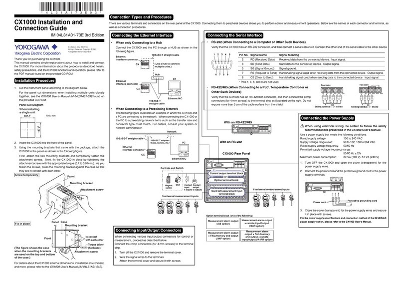
YOKOGAWA
YOKOGAWA CX1000 Installation and connection guide
AIRTRONICS
AIRTRONICS 90405 operating manual
Steca
Steca TR 0704 Installation and operating manual
SKF
SKF Runner Installation, operation and maintenance manual
Philips
Philips dynalite DDBC120-DALI quick start guide

SWASTIK
SWASTIK DTC-9621-1 instruction manual
Sporlan
Sporlan Superheat Installation and operation instructions
FrSky
FrSky Pilot Series instruction manual
Chamberlain
Chamberlain LA500UL Wiring diagram
Mitsubishi Electric
Mitsubishi Electric MELSERVO-J5 MR-J5-G Series user manual
