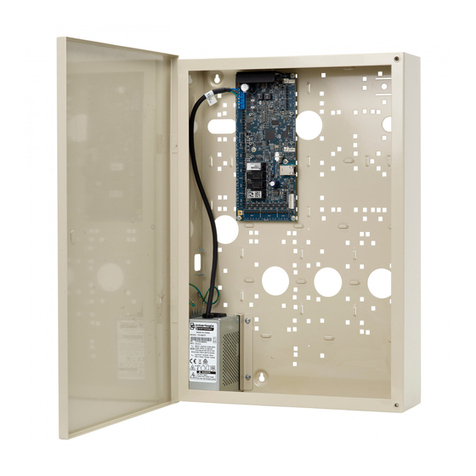
Steca TR 0704 User manual

SOLARTHERMIE - SOLAR THERMAL - SOLAR TÉRMICO- SOLAIRE THERMIQUE - SOLARE TERMICO
Installation and Operating Manual
System Regulator for Solar Thermal Systems
7 inputs, 4 outputs
709.756 | Z02 | 08.08 | Änderungen aufgrund technischer Verbesserungen vorbehalten!
EN
These operating instructions are part of the product.
Read these operating instructions carefully before use.
Keep them over the entire lifetime of the product
and pass them on to any future owner or user of this product.

2
Content
1SECURITY INSTRUCTIONS AND RESTRICTION OF LIABILITY..................... 4
1.1 Sign for security instructions.........................................................................4
1.2 General safety instructions............................................................................4
1.3 Regarding these instructions.........................................................................4
1.4 Restriction of liability ....................................................................................4
2INSTALLATION AND OPERATION ...................................................................5
2.1 Location of installation .................................................................................5
2.2 Installation ....................................................................................................5
2.3 Regulator Connection ...................................................................................6
3OPERATING THE SYSTEM REGULATOR........................................................8
3.1 Basic Menu....................................................................................................8
3.2 Measuring Values Menu ...............................................................................8
3.3 Operating Status Menu.................................................................................9
3.4 Parameter Menu .........................................................................................10
3.5 Date/Time Menu .........................................................................................11
3.6 Clocks Menu ...............................................................................................11
3.7 System Selection Menu ...............................................................................11
3.8 Functions Menu ..........................................................................................11
3.9 Links Menu..................................................................................................12
3.10 Extras Menu ................................................................................................12
3.11 Manual Operation Menu.............................................................................12
4SYSTEM SELECTION ......................................................................................13
4.1 Systems with Internal Heat Exchanger ........................................................15
4.2 Systems with Plate Heat Exchanger ............................................................41
4.3 Systems for Supplementary Heating ...........................................................51
5FUNCTIONS...................................................................................................... 57
5.1 Thermostats ................................................................................................57
5.2 Differential Thermostats .............................................................................58
5.3 Radiation Switches......................................................................................58
5.4 Time Functions............................................................................................59
5.5 Pipe Coll./Interval ........................................................................................59
5.6 Heat Meters ................................................................................................59
5.7 Additional Measuring Values ......................................................................60
5.8 Collector Temperature Limitation ...............................................................60
5.9 DVGW Heating............................................................................................61
5.10 Synchronous Output ...................................................................................62
5.11 Frost Protection...........................................................................................62
5.12 Fresh Water at R2........................................................................................63
6LINKS................................................................................................................64

3
7SYSTEM EXAMPLES........................................................................................65
7.1 Circulation Function ...................................................................................65
7.2 Stop after-heating in the Morning..............................................................66
7.3 Supplementary Heating ..............................................................................67
7.4 Solid Fuel Boilers.........................................................................................68
7.5 Recharging Storage Tanks ..........................................................................69
7.6 Swimming Pool Heating .............................................................................70
7.7 Bypass in the Solar Circuit ..........................................................................71
8CONFIGURATION.............................................................................................72
9SYSTEM EXPANSION ......................................................................................72
9.1 IS-Bus..........................................................................................................73
9.2 RS 232 ........................................................................................................73
9.3 Add-on and Alarm Outputs ........................................................................75
10 INFORMATION FOR TROUBLESHOOTING ................................................76
11 LEGAL GUARANTEE....................................................................................79
12 TECHNICAL DATA........................................................................................80

4
1Security instructions and restriction of liability
1.1 Sign for security instructions
Security instructions for personal safety are marked with this sign and are printed in bold letters.
Instructions that refer to the functioning safety of the system are also printed in bold letters.
1.2 General safety instructions
For your own safety please note the following for installation:
Please see that fire safety cable systems and similar things are not impaired!
The controller must not be installed and used in moist areas (e. g. bathrooms) or in rooms in which
flammable gas mixtures (by gas bottles, paint, solvents etc.) are likely to occur!
Do not store any of the above and similar things in rooms where the solar controller is installed!
The controller must not be installed on a conductive base!
Use well-isolated tools only!
Do not use technical equipment that is defective or broken!
The construction safety measures can deteriorate if the controller is used in a way other than the one
determined by the manufacturer.
The preset signs and marks must not be changed, removed or made illegible.
All operations must be conducted in accordance with the national electricity regulations and local
rules!
For installation in foreign countries please see your corresponding institutions for information on
regulations and safety measures.
Keep children away from electronics!
1.3 Regarding these instructions
These operating instructions describe the functioning and installation of a controller for thermal solar
systems for feeding solar heat into a water or buffer store.
For the installation of the other components such as the solar collectors, pump group and the storage
basins please follow the corresponding installation instructions of the manufacturer.
Before starting operation read the paragraph "installation and operation" no. 5 and make sure that all
measurements have been prepared before.
Only begin with the installation when you have understood this instruction and proceed in sequence!
These instructions must be handed out to all persons that work with this system.
These instructions are part of the system controller and must be handed over in case the controller is
sold.
1.4 Restriction of liability
The manufacturer cannot monitor the compliance with these instructions or the circumstances and
methods used for installation, operation, utilization and maintenance of this controller.
Improper installation can cause damages to material and persons.
This is the reason why we do not take over responsibility and liability for losses, damages or cost that
might arise due to improper installation, operation or wrong utilization and maintenance or that occur
in some connection with the afore-mentioned.
Moreover we do not take over liability for patent infringements or infringements - occuring in
connection with the use of this controller - on third parties´ rights.
The manufacturer preserves the right to put changes to product, technical data or installation and
operation instructions without prior notice.
NOTE: Opening the device – connecting case excluded – as well as other use than determined
by the manufacturer leads to a loss of warranty.

5
2Installation and operation
The following must be observed when performing electrical work on the regulator:
Depending on the version, the regulator is designed for use with 115V or 230V (±15 %) alternating
voltage with a frequency of 50 or 60Hz (see rating plate). Operation with different ratings is not
permitted. Also ensure the permitted current ratings are not exceeded.
If an Earth conductor is intended or required for the pump, the Earth conductor must be connected.
The corresponding Earth conductor wire terminals are provided. Ensure that the ground contact is also
connected to the regulator’s mains supply side. Cables, which are not permanently connected with the
building must be provided with a strain relief outside the regulator.
The regulator may only be used for the intended purposes. No liability shall be assumed for any non-
compliant usage.
Any work with an open regulator may only be carried out if the mains power is disconnected.
All safety regulations for working with the mains apply here. The connection, and any work
where the regulator has to be opened, may only be carried out by trained electricians. The
regulator is protected against overcharging and short circuiting.
2.1 Location of installation
The controller is designed for installation on vertical walls. It must not be installed in areas where you
can find flammable liquids or gases. It is only allowed to install the controller in areas in which the
protective system (see Technical data) is sufficient.
The max. permissible ambient temperature at the place of installation must never be exceeded or
fallen below. Moreover, the controller must not be used in moist rooms (bathrooms) or in rooms in
which flammable gas mixtures (by gas bottles, paint, solvents etc.) are likely to occur!
fig.1: Installation
2.2 Installation
Wall mounting
The upper regulator cover (fig.1, no. 1) protects the regulator’s electronics and may not be removed
for installation purposes.
Screw 1 must first be screwed into the wall to mount the regulator. The regulator is subsequently hung
on this screw with the cutout (fig.1, no. 2). The regulator can be used as a template to mark the two
other mounting holes (fig.1, pos. 3 and 4).
(Warning: only use the regulator as a marking template, never as a drilling template).
After tightening the controller to the wall, you can start with the wiring.
215,00
193,00
130,00
150,00

6
2.3 Regulator Connection
First of all leave open the wire entrances for the
power supply connection and the connecting wires of
the sensors and the pump in the casing box. For this
purpose there are material draws to be cut out (fig.2,
Pos. 1). Each wire entrance needs two vertical cuts
into the wall of the plastic case. For the cutting you
can use cable stripping knife or an electronic side
cutter. The cutting depth should be 2 mm min. from
the plastic case ground. Afterwards the plastic clip
can be taken out by moving it back and forth.
The lines outside the regulator must be strain-
relieved (e.g. with strain relief clamps). Alternatively, the cable inlets can be equipped with a housing-
specific strain relief from the manufacturer. If the regulator must be wired through the back panel of
the housing, there are also cut-outs available for PG screw fittings (fig.1, pos. 5) - PG 9.
The connecting activities as described here are only possible when the terminal box
cover plate of the controller is open. For this purpose clear the power supply net. Stick to
all valid regulations for working on a cleared power supply net. Only connect to the
power supply net when controller case is closed. Moreover, the user has to take care of
the fact that the IP protection is not damaged.
The connection of the individual pumps or valves
depends on the layout plan. Therefore in chapter 4, a
corresponding terminal connection table is provided for
each diagram. If a protective Earth wire is provided or
required for pumps or switch valves the Earth wire must
be connected. The corresponding connection terminals
are provided. Ensure the Earth wire is also connected to
the regulator on the mains supply side.
Each terminal may be allocated only one connecting
cable (up to 2.5mm²). Connector sleeves must be used
with finely stranded cables.
fig.4: Terminal connection table for the mains supply
Abb.3: Betätigung der Anschlußklemmen
cut-out 1
fig.2: material cut-out for wire entrance
fig.3: Actuation of connection terminals

7
R4 output (230V switch output or voltage-free output):
R4 switch
output 230V: R4 voltage free
output:
fig.5:
Connection variants for R4 output
To simplify things, the R4 output has
always been displayed as a 230V
switch output in chapter 4.
However, the output - as shown here
- can also be wired as a potential-
free output as required.
Temperature sensors
Warning: Only the original sensors permitted for the regulator may be used. These are Pt1000 type
sensors. The polarity of the sensor contacts is irrelevant when connecting.
The sensor cables can be extended up to a length of around 100m. To do this, use an extension cable
cross section of 1.5mm² up to 100m and 0.75mm² up to 50m.
Radiation sensors
Warning: Only the original radiation sensors permitted
for the regulator may be used. Since these sensors are
active components, correct polarity must be ensured
when connecting.
fig.6: Radiation sensor connection
Pulse generators If pulse generators are used with a
“reed switch” the connection polarity
is arbitrary. Ensure the correct
polarity, when using an "open
collector" circuit.
fig.7: Volume Flow Meter
All sensor cables are low voltage and must be installed separately from current-carrying power
lines (minimum distance 100 mm) to prevent external inductive interference. If external
inductive interferences, for example by heavy current cables, contact wires, transformer
stations, radio and television sets, amateur radio stations, microwave devices, or similar
devices are to be expected, the cables carrying the measuring signal must be shielded.
The mains can be switched on once the terminal area is closed with the terminal cover and the
corresponding housing screw.
The date and time must appear in the regulator’s LCD display when the mains is switched on.
The date and time will have to be reset if the regulator’s power supply has be disconnected for
a long time.
E1 to
E7
REED- or mech. contact :
E1 to
E7
Open collector:
blue
red
E6 or E7
clam
p

8
3Operating the System Regulator
The regulator allows the solar thermal system operator to create a system matching his/her own user
profile. This is ensured by various setting options for parameters and service functions. The
performance of the system is easily monitored due to the numerous measured data and above all the
graphic visualization of the data. Operating the system’s regulator is subsequently described in detail.
Menu diagrams clarify the selection options here and provide an overall summary of the regulator’s
navigation.
3.1 Basic Menu
Use the (UP) or (DOWN) buttons to browse
through the menu.
Select the individual subdirectories with the OK button.
To protect against unintentional changes to the
regulator functions, all directories in the ‘Service’
menu have a "child-proof lock". Press the OK and
Menu button simultaneously for 2 seconds to open
these directories.
Press the OK button for 2 seconds to select or change
a setting.
Press the Menu button to return to a previous menu.
*) The 'Clocks' submenu can only be opened if one or
more clocks have been previously activated under
Functions!!!
**) The Links subdirectory is only displayed in the menu
if selected functions must be linked!!!
3.2 Measuring Values Menu
All measuring values recorded by the regulator are displayed in the 'Measuring values' submenu. After
opening the menu, the current measuring values are listed as numerical values.
The measured data saved in the integrated data logger can also be graphically displayed. The
temperature progressions in the last 15 days can be displayed in the temperatures. Graphics of the
operating hours both for the last 15 days and the last 13 months are available for evaluating the pump
running times. Radiation, power and flow rate values have graphics covering the last 15 days, last 13
months, last 5 years and also an annual overview.
The operating hours of the outputs used are recorded during the entire running time and are
continually added up (“Σ”). In addition, the user can record the operating hours for an arbitrary time
period (“Δ”) and then reset them. Select the value of the operating hours “Δ” and press the OK button
for 2 seconds to reset the operating hours.
Please note that the summed up displays for operating hours, flow rate and amount of heat do
not reset to 0 after 99´999. Instead, for storage space reasons, they reset after 15´000 h
(operating hours), 15´000kWh (heat quantity) and 50´000l (flow rate).
-
-
-
Date / Time...
Service
S
y
stem selection...
Links... **
Manual o
p
eration...
Measurin
g
values...
O
p
eratin
g
status...
Settin
g
s
Parameter...
Functions...
Extras...
Clocks *

9
Call up (OK button) a selected
measuring value to open the
relevant graphic menu. The
individual days, months or
years can now be called up
with the buttons.
Press the OK button to change
between the day, month and
year records.
In addition to the temporal
progressions, the minimum and
maximum values are also
displayed in the records. The
scale of each individual graphic
is automatically adjusted to the
minimum and maximum values
reached, through which the
graphs sustain the utmost
accuracy.
fig.8: Records of measuring values
Note: The graphically displayed values are average values taken over a 15 minute measuring
time. Instantaneous fluctuations in the measuring values cannot be displayed in the
records. Since only an aberrant average value can be displayed in the graphics, and not
the reached threshold value, switching thresholds of the control system cannot be precisely
incorporated into the records.
Press the Menu button at any time to exit the graphic menu.
3.3 Operating Status Menu
The 'Operating status' submenu provides the user with a quick overview of the
operating status of the individual pumps or valves and any possible system
error messages.
Depending on the size of the system, as shown in fig.9, the operating status of
the connected extension units (see chapter 9.1 for additional IO boxes) is also
displayed.
The status of the individual outputs – regardless of whether a pump, a valve or
nothing is connected to them – is displayed by a pump symbol . The pump
symbol does not move in a current-less state. If an output is active, the
corresponding symbol rotates.
The status or error display provides information on which errors, if any, are
present on the regulator. If "Status ok" appears in the display, no errors are
present. If, however, errors have been detected (e.g. interruptions or short
circuits in the temperature sensors’ cables), they flash in the display [e.g.:
"Interrupt. E1 (regulator)"]. After being rectified, the individual error messages
must be successively acknowledged. If an error message is acknowledged
without the rectifying its cause, the error is displayed again a few seconds
after being acknowledged.
As long as an error message is displayed, the regulator’s alarm output (see
chapter 9.3) is active. The alarm output is deactivated, once the error is
rectified and successfully acknowledged.
fig.9: 'Operating status' menu
Measuring values ...
Ope ratin g s tatu s ...
+ Settings
collector 1: 21°C
storage 1 bottom: 47°C
op. hours R1
Δ
: 112h
op. hours R1
Σ
: 919h
OK Menu
OK Menu
OK
OK Menu
values of the last 15 days values of the last 15 days
values of the last 13 month
OK
values of the last 15 days
values of the last 13 month
OK
values of the last 5 years
OK
overview of the last 5 years
radiation: 9 W/qm
therm. power: 0 W
flow rate: 183 l/h
OK Menu
daily
overview
monthly
overview
yearly
overview
5 years'
overview
storage 1 bottom: 47°C
op. hours R1
Δ
:
112
h
op. hours R1
Σ
:919h
M e as uring valu es ...
Ope ratin g s tatu s ...
+ Settings
regulator:
status: ok
OK Menu
R1 R2 R3 R4
IO-Box 1:
status: ok
R1 R2 R3
IO-Box 2:
status: ok
R1 R2 R3
IO-Box 3:
status: ok
R1 R2 R3
IO-Box 4:
status: ok
R1 R2 R3

10
fig.10: Overview of the 'Settings' menu
3.4 Parameter Menu
All threshold and hysteresis values of the selected layout plan are listed
in the 'Parameter' menu window. The regulator is factory set so that it
can be used for most applications without changing these values. All
parameters can be changed within certain limits, thus allowing the
system to be individually personalized. Select the corresponding
parameter. Press the OK button for 2 seconds to adjust the selected
value (value flashes). You can now change the parameter with the
buttons and save it by again pressing the OK button for 2 seconds.
Some values can only be adjusted in certain areas or are mutually
locked to prevent erroneous settings.
If a layout plan with several storage tanks has been selected, the
'storage tank priority' of the individual storage tank must be specified.
In the 'storage tank priority...' submenu, the priority order of the
individual storage tank can be checked and, if necessary, changed. The
priority order is factory set based on the respective storage tank name
(i.e. first storage tank 1; before storage tank 2; before storage tank 3;
etc.). This setting can be changed at any time. Press the OK button for
2 seconds to move the selected storage tank within the priority list
(name flashes). Use the buttons move the storage tank within the
list and save it by again pressing the OK button for 2 seconds.
Operation of the storage tank priority is described in more detail with
the corresponding systems (chapter 4).
The regulator has two electronic relays for the speed control of circulating pumps. The speed control
can be separately activated or deactivated for each of these outputs. Both speed controls are
activated as a factory setting (:). If, however, the outputs are operated as pure switch outputs, this
control system must be deactivated (:--2sec-->).
The respective regulator settings can be adjusted in the 'Settings‘ submenu. The speed control of the
pumps is for regulating the temperature. Depending on the selected setting, either the differential
temperature or the absolute temperature is held to a constant value. The sensor values, on which the
differential and absolute temperature are based, are determined by the selected layout plan and
cannot be changed.
Press the Menu button to return to the previous menu.
Measuring values ...
Ope rating s tatu s ...
+ Settings
Ope ratin g s tatus ...
- Settings
Param eter...
Date / T im e ...
+ Clocks
+ Service
storage 1 max.: 60°C
Diff. temp. solar1 ON: 8 K
Diff. temp. solar1 OFF: 4 K
. . .
OK
OK
Param eter...
Date / Tim e...
+ Clocks
OK
- Settings
Param eter...
Date / Tim e...
+ Service
Tue 01.01.2002
Tim e : 08:00
OK
Date / Tim e...
+ Clocks
+ Service
+ Clocks
- Service
Sys tem s election...
Functions...
L in k s ... *
Extras ...
M anual o pe ration ...
Date / Tim e...
OK
Menu Menu
Menu
+ Clocks
+ Service
- Clocks
Clock 1...
Clock 2...
Clock 3...
The 'Clocks' submenu can only
be opened if one or more clocks
have been previouslyactivated
under submenu 'Functioncs' !!!
*)The 'Links' subdirectory is only
displayed in the menu if
selected functions must be
linked !!!
Parameter...
Date / Time...
+ Clocks
+ Service
storage max. 60°C
collector max. 130°C
Diff. Temp. solar ON: 8 K
. . .
Menu
Storage tank priority...
+ speed control
R1 (regulator)
Settings...
R2 (regulator)
Settings...
OK
x
x
control aim: absolute temp.
min. speed control [%]: 30
OK Menu
OK
- speed control
Fig.11: 'Parameters' menu

11
3.5 Date/Time Menu
The date and time can be set or changed in the 'Date/Time' menu window (see fig.10). The date is
entered separately according to day, month and year. The corresponding day of the week is
independently calculated by the system regulator.
Press the OK button for 2 seconds to set the day’s date (day flashes). You can now set the day with
the buttons. Confirm the day entry (OK button) to change to the month entry (month flashes). You
can now set the month with the buttons. Confirm the month entry (OK button) to change to the
year entry (year flashes). You can now set the year with the buttons and save the full date by
confirming again (OK button). The regulator then calculates the corresponding day of the week.
The time is entered in the same way, and is separated by hours and minutes.
Daylight savings time is changed automatically by the regulator. However, this only applies until
2007, because the 2000/84/EC directive (EC directive on time change) expires in 2007 and no political
decision has yet been made for the period thereafter.
In the event of a power failure the date and time will be retained for more than 12 hours.
Press the Menu button to return to the previous menu.
3.6 Clocks Menu
In the 'Clocks' menu window the switching times available for the functions can be changed quickly
without having to individually open every relevant function. In total, up to 3 independent clocks are
available. After being opened, the menu window only shows the clocks used under Functions. If thus
far, no time functions have been activated, this menu window can not be opened!!!
Each clock can be programmed with 5 time intervals for week days (Mo to Fr) and 5 time intervals for
the weekend (Sa and Su). Entering or changing time intervals is performed separately by hours and
minutes. Press the OK button for 2 seconds to set the hour of the selected time (hour value flashes).
You can now set the hour with the buttons. Confirm the hour entry (OK button) to change to the
minute entry (minute value flashes). You can now set the minutes with the buttons and save the
time by confirming again (OK button).
Press the Menu button to return to the previous menu.
3.7 System Selection Menu
Important: The 'System selection' menu window is part of the 'Service' menu and is therefore
additionally protected against unintentional changes. Hold the OK and Menu buttons
simultaneously for 2 seconds to open this menu window ("child-proof lock").
Before a new layout plan can be selected the current layout plan must first be
deactivated (press OK 2 sec.)!!!
The layout plan can be assigned in steps with several substructures.
More detailed information on the correct system selection in found in chapter 4.
3.8 Functions Menu
Important: The 'Functions' menu window is part of the 'Service' menu and is therefore additionally
protected against unintentional changes. Hold the OK and Menu buttons simultaneously
for 2 seconds to open this menu window ("child-proof lock").
More detailed information on the possible functions is found in chapter 5.

12
3.9 Links Menu
This menu window is only shown in the menu if linking selected functions is required or
possible !!!
Important: The 'Links' menu window is part of the 'Service' menu and is therefore additionally
protected against unintentional changes. Hold the OK and Menu buttons simultaneously
for 2 seconds to open this menu window ("child-proof lock").
More detailed information on creating links is found in chapter 6.
3.10 Extras Menu
The ‘Extras' menu window contains the 'display contrast', 'factory settings' and 'delete records' option
box.
The contrast of the display can be changed with 'display contrast'. Press the OK button for 2
seconds to set the value (value flashes). You can now change the contrast with the buttons and
save it by pressing the OK button again for 2 seconds.
Reset the system regulator to the as supplied condition with 'factory settings.
Please observe that individually adjusted setting parameters and selected
functions must be subsequently readjusted to the corresponding system.
Select 'factory settings' and press the OK button for 2 seconds to reset the system
regulator to the as supplied condition. For confirmation 'ok' appears until the menu
is exited. Please contact your specialist dealer, if you are not confident enough to
configure the regulator yourself. No liability shall be assumed for any damage
caused by regulators incorrectly set!
Press the OK button for 2 seconds with 'delete records' to delete the measuring value records saved
to date (see chap 3.3). For confirmation 'ok' appears until the menu is exited.
3.11 Manual Operation Menu
Important: The 'Manual operation' menu window is part of the 'Service' menu and is therefore
additionally protected against unintentional changes. Hold the OK and Menu button
simultaneously for 2 seconds to open this menu window ("child-proof lock").
All used switch outputs for the system regulator and any connected add-
on modules – called IO boxes – (see ch. 9.1) can be switched on or off for
testing purposes (e.g. after maintenance and repair work) in the 'Manual
operation' menu window. For clarity reasons, only the displayed alarm
output (see chapter 9.3) and outputs, which are used by the applied layout
plan or selected functions.
To change an output’s switching status, select the output to be changed
and press the OK button for 2 seconds. This setting remains active until
the output is deactivated again by pressing the OK button for 2 seconds
or the 'Manual operation' submenu is exited via the Menu button.
Warning:
The regulator switches back to automatic mode after the 'Manual
operation' exiting submenu.
This means: this menu must be exited again after finishing
maintenance and repair work.
Links...
Extras...
Manual operation...
R1 (regulator) off
R2 (regulator) off
R3 (regulator) off
R4 (regulato r) of f
R1 (IOBo x 1) off
. . .
Alarm output off
Menu
OK + Menu
(2 sec)
R1 (regulator) on
R2 (regulator) off
R3 (regulator) off
OK (2 sec.)
R4 (regulator) off
OK (2 sec.)
Fig.12:
'Manual operation'
menu

13
4System Selection
The system regulator has a database with more than 70 pre-programmed solar systems.
The corresponding basic system must be selected in the regulator before commissioning the system.
The connection of sensors, pumps and/or valves is also dependent on the present system. All basic
systems, their electrical terminal connection table and a brief menu overview are displayed in the
following chapter. The pre-programmed systems can be roughly differentiated as follows:
4.1 Systems with internal heat exchanger:
4.1.1 Systems with 1 storage tank and 1 collector array
4.1.2 Systems with 1 storage tank and 2 collector arrays
4.1.3 Systems with 2 storage tanks and 1 collector array
4.1.4 Systems with 2 storage tanks and 2 collector arrays
4.1.5 Systems with 3 storage tanks and 1 collector array
4.1.6 Systems with 3 storage tanks and 2 collector arrays
4.1.7 Systems with 4 storage tanks and 1 collector array
4.2 Systems with plate heat exchanger:
4.2.1 Systems with 1 storage tank
4.2.2 Systems with 2 storage tanks
4.2.3 Systems with 3 storage tanks
4.2.4 Systems with buffer tank and fresh water function
4.2.5 Systems with buffer tank and preheating storage tank
4.3 Systems for heating support:
4.3.1 Systems with 1 combi storage tank and internal heat exchanger
4.3.2 Systems with 1 combi storage tank and plate heat exchanger
4.3.3 Systems with 2 storage tanks
Before a new layout plan can be selected, the current layout plan must first be deactivated
(press OK 2 sec.)! As long as no layout plan has been selected, the 'System selection...' menu
cannot be exited with the 'Menu' button!
The hydraulic plans displayed in the following chapter only depict a schematic diagram. They are only
meant as an aid to understanding and are in no respect a substitute for professional system planning.
The system regulator provides these system groups in a basic version ('Basic') and with different add-
ons ('-Ci' , '-AH' , '-SFH' , '-CZ' , '-R').
These add-ons are explained in more detail in the following:
Circulation control: '-Ci '
Some of the pre-programmed solar heating systems offer a circulation control as an add-on for the hot
water circuit. This function requires a temperature sensor on the return line of the circulation line and a
circulation pump. In the event the hot water circuit falls below the set value (parameter: 'circulation
ON') the corresponding circulation pump is activated and runs until the adjustable switch-off value
(parameter: 'circulation OFF') is reached.
Important: When installing the sensor there should be a minimum distance of 1.5m to the storage
tank, to prevent erroneous measurements due to the thermal conduction of the pipe.
After-heating Control: '-AH '
Some of the pre-programmed solar heating systems offer an after-heating control as an add-on for
one of the storage tanks. This function requires a temperature sensor in the upper part of the storage
tank and a heating circuit pump or a boiler control with potential-free controlling (e.g. condensing gas
boiler). In the event the temperature falls below the set value (parameter: 'after-heating ON') the
corresponding heating circuit pump or boiler control is activated and runs until the adjustable switch-off
value (parameter: ‘after-heating OFF') is reached.
Attention: Please observe that a heating circuit pump at the R4 output can be controlled either
directly with 230V (e.g. an older boiler) (factory-installed terminal jumper must be fitted) or indirectly
via a separate boiler control (e.g. gas condensing boiler) and the potential-free R4 switch output
(factory-installed terminal jumper must be removed as otherwise the boiler control system can be
destroyed).
For graphical reasons the after-heating is always shown with a heating pump in the following hydraulic
diagrams. Naturally, separate boiler controls can also be used.

14
After-heating control with solid fuel boiler: '-SFH '
Some of the pre-programmed solar heating systems offer an after-heating control with a solid fuel
boiler as an add-on. This function requires a temperature sensor in the upper part of the storage tank,
a temperature sensor on the solid fuel boiler and a heating circuit pump.
In the event the temperature falls below the set value (parameter: 'solid fuel heat. ON') in the upper
part of the storage tank, the control device automatically checks if the solid fuel boiler has reached the
set minimum temperature 'boiler temp. min.' at the boiler sensor. Only in this case is the heating circuit
pump switched on. When the storage tank reaches its set switch-off temperature (parameter: 'solid
fuel heat. OFF'), the heating circuit pump is switched off again. During the charging process the
control device continuously checks the temperatures of the solid fuel boiler as well. If the boiler
exceeds its set temperature limit (parameter: 'boiler temp. min.' and 'boiler temp. max.') the heating
circuit pump will also be switched off.
Charging Zone Control: '-CZ ' (only with systems with plate heat exchanger)
Some of the pre-programmed solar heating systems provide a charging zone control as an add-on to
utilize a simple layer in the storage tank. This function requires an additional temperature sensor in the
storage tank (in the additional charging inlet area) and a 3-way valve.
While the 'Basic' control always charges the storage tank at the top (this can, under certain
circumstances, mix an existing layer), the temperature in the middle part of the storage tank is also
factored in by this control system. As soon as the charging temperature (measured on the secondary
side of the plate heat exchanger) is at least 2 Kelvin above the temperature in the middle part of the
storage tank, the regulator starts to charge the upper part of the storage tank. If the charge current
only provides temperatures lower than or the same as the 'middle of the storage tank‘ temperature, the
charging current is diverted back to the middle storage tank area. The objective of the control device,
however, is the required charging temperature (parameter: ‘charging setpoint'). To prevent the after-
heating function from being inadvertently activated, systems with after-heating (-AH) or external after-
heating as well as the after-heating parameters 'after-heating OFF or 'AH extern. threshold ' are also
factored in by the switch valve’s control.
Systems with after-heating (-AH) can only be switched to the upper charging zone, when the charging
temperature is at least 2 Kelvin above the switching parameter 'after-heating OFF'. If the charging
current only returns temperatures lower than or the same as this parameter, the charging current is
diverted back to the middle storage tank area.
Systems with external after-heating (ext. AH) can only be switched to the upper charging zone when
the charging temperature is at least 3 Kelvin above the switching parameter 'AH extern. threshold '. If
the charging current only returns temperatures, which are 1K above this parameter, the charging
current is diverted back to the middle storage tank area.
Important: To prevent mixing the hot upper area, the 3-way valve must be installed so that the
middle storage tank area is charged in a de-energized state!
Radiation Sensor Control: '-R '
Some of the pre-programmed solar systems offer a solar circuit control through a radiation sensor as
an add-on. This function requires one radiation sensor for each collector array.
In comparison with the 'Basic' control, this control activates the solar pump depending on the
measured radiated power. If the solar radiation reaches the set threshold value (parameter: 'solar circ.
ON'), the solar pump is activated. To prevent possible cold water charging (e.g. when snow is on the
collector array), a bypass valve must be provided in the solar flow (advance) for systems with an
internal heat exchanger that only allows the storage tanks to be charged when a sufficiently high
temperature has been reached (solar advance temp. >= storage tank temp.+6K). The pump is first
deactivated as soon as the radiated power falls below the set value (parameter: 'solar circ. OFF') or
the storage tank or collector have reached their maximum/minimum temperatures.
Important:The speed control of the solar pump (if provided) refers to the differential temperature
between the solar flow (advance) (T1) and the lower storage tank temperature or to the absolute
temperature of the solar flow (advance) (T1) – depending on the speed control setting (see ch. 3.5).
For this reason temperature sensor T1 (and possibly also T2) are essential. T1 (T2) must therefore be
installed in the place described in the layout plan between the collector and storage tank!
Important: The control device can only work properly when the 3-way valve has been installed so that it is
in bypass position in a de-energized state!

15
4.1 Systems with Internal Heat Exchanger
4.1.1 Internal heat exchanger, 1 storage tank, 1 collector array
If, in the 'System selection'
menu,
the points
"intern. heat exchanger",
"1 storage tank" and
"1 collector" are selected,
the hydraulic diagram
illustrated here is available
for use as a basic system
(basic) with the indicated
variants.
•"Basic" diagram: As soon as the differential temperature between T1 and T2 reaches the set
value (parameter: 'diff. temp. solar ON'), the solar circuit pump R1 is activated. If the storage tank
reaches its maximum storing temperature (parameter: 'storage max.') or in the event it falls below
the switch-off differential temperature (parameter: 'diff. temp. solar OFF'), the pump switches off.
Depending on the setting (parameter -> speed control -> R1) the solar pump’s speed control
maintains the differential temperature between 'collector' (T1) and ‘lower part of the storage tank'
(T2) at the value of the 'diff. temp. solar ON' parameter or the absolute temperature of the
'collector' (T1) constant at a fixed temperature of 70°C.
The additional functions shown (circulation and the two after-heaters) are not activated.
•Add-on " - Ci": Output R2 and the T4 temperature sensor can also provide a control of a
circulation pump for the warm water cycle. A detailed functional description of the add-on with
further tips can be found on page 14.
•Add-on " - AH": R4 and T3 combined with an oil or gas boiler can provide after-heating. A detailed
functional description of this add-on can be found on page 15.
•Add-on " - SFH": With the help of R3, T3 and T5 after-heating is also possible considering the
boiler temperature (required, for example, when burning solids). A detailed functional description
of this add-on works can be found on page 15.
•"Basic - R" diagram: In some cases the solar circuit pump must be controlled according to the
solar radiation. For this purpose a radiation sensor S7 must be installed in the collector level. For
control reasons, T1 must be inserted between the collector and bypass. A detailed functional
description of this add-on can be found on page 15.
To prevent erroneous settings, the described switch-on and switch-off values are interlocked,
this means they can be set only at a specific value to one another.
T2
R1
T4
R2
Basic-
Ci
T5
T3
R3 solid
fuel
Basic-
SFH
R4
T3
oil,
gas
Basic-
AH
or S7 (Radiation sensor for Basic-R)
M
R2
Bypass for
Basic-R

16
Connecting diagram:
Menu navigation: (here for the scheme 'Basic' )
OK
Measuring values collector: °C
Operating status storage bottom: °C
+Settings
sola
r
-
p
um
p
Δ: h
OK OK
sola
r
-
p
um
p
Σ: h
Parameter storage max. 60°C
Date / Time collector max. 130°C
+Clocks Diff. temp. solar ON 8K
+Service Diff. temp. solar OFF 4K
OK OK + Menu (2 sec.) +speed control
System selection -intern. heat exchanger
Functions OK
Links -1storage tank
Extras OK
Manual operation -1collector
OK
~Basic choose with OK (2sec.)
{Basic-AH
{Basic-AH-SFH
{Basic-AH-SFH-Ci
{Basic-AH-Ci
{Basic-SFH
{Basic-SFH-Ci
{Basic-R
{Basic-Ci
S7
T3 T4 T5
R2 R3 R4

17
4.1.2 Internal heat exchanger, 1 storage tank, 2 collector arrays
4.1.2.1 Internal heat exchanger, 1 storage tank, 2 collector arrays, valve control
If, in the 'System
selection' menu,
the points
"intern. heat exchanger",
"1 storage tank",
"2 collectors" and
"Basic V" are selected,
the hydraulic diagram
illustrated here is
available for use as a
basic system with the
indicated variants.
•"Basic V" diagram: The regulator constantly records the differential temperature between the
sensors T1 and T3 or T2 and T3. If the set switch-on differential temperature (parameter: 'diff.
temp. solar ON') is reached, pump R1 is activated and the 3-way valve R2 is switched so that the
corresponding collector array can be run through. While the storage tank is charged, the option of
switching to the other collector array is constantly checked. A condition for switching is that the
temperature of the passive collector array must be an adjustable value (parameter: 'switch collect.')
higher than that of the active array. The storage tank is charged irrespective of which collector
array is active until the value for the maximum storing temperature (parameter: 'storage max.') is
reached or falls below the switch-off differential temperature (parameter: 'diff. temp. solar OFF'). If
this is the case, the solar circuit pump and the switch valve are switched off.
Definition:When the 3-way valve is switched off, the collector array 1 is flown through!
Depending on the setting (parameter -> speed control -> R1), the solar pump’s speed control
maintains the differential temperature between 'collector' (T1 or T2) and ‘lower part of the storage
tank' (T3) at the value of the parameter 'diff. temp. solar ON' or the absolute temperature of the
'collector' (T1 or T2) constant at a fixed temperature of 70°C.
The additional functions shown (circulation and the two after-heating systems) are not activated.
•Add-on " - Ci": Output R3 and the T4 temperature sensor can also provide a control of a circulation
pump for the warm water cycle. A detailed functional description of the add-on with further tips can
be found on page 14.
•Add-on " - AH": R4 and T5 combined with an oil or gas boiler can provide after-heating. A detailed
functional description of this add-on can be found on page 15.
•Add-on " - SFH": With the help of R3, T4 and T5 after-heating is also possible considering the
boiler temperature (required, for example, when burning solids). A detailed functional description of
this add-on works can be found on page 15.
R4
T5
oil,
gas
Basic
-AH
T4
R3
Basic
-Ci
alternative radiation sensor for BasicV-R
T4
T5
R3 solid
fuel
Basic
-SFH
R3
M
Bypass for
BasisV-R
S6 S7

18
•"Basic V - R" diagram: In some cases the solar circuit pump needs to be controlled according to
the solar radiation. For this purpose the radiation sensors S6 and S7 must be installed in the
corresponding collector levels. For control reasons, T1 must be inserted between the collector’s
collection point and bypass. The temperature sensor T2 is not required. A functional description of
this add-on can be found on page 15.
To prevent erroneous settings, the described switch-on and switch-off values are interlocked,
this means they can be set only at a specific value to one another.
Connecting diagram:
Menu navigation: (here for the scheme 'Basic V' )
OK
Measuring values collector 1: °C
Operating status collector 2: °C
+Settings storage bottom: °C
OK OK
sola
r
-
p
um
p
Δ: h
Parameter storage max. 60°C
sola
r
-
p
um
p
Σ: h
Date / Time collector max. 130°C
reversin
g
valve Δ:h
+Clocks Diff. temp. solar ON 8K reversin
g
valve Σ:h
+Service Diff. temp. solar OFF 4K
OK OK + Menu (2 sec.) switch collect. 10K
System selection -intern. heat exchanger +speed control
Functions OK
Links -1storage tank
Extras OK
Manual operation +1collector
- 2collector
OK
{BasicP
......
~BasicV choose with OK (2sec.)
{BasicV-AH
{BasicV-AH-SFH
{BasicV-AH-Ci
{BasicV-SFH
{BasicV-R
{BasicV-Ci
T4 T5
R3 R4
M
S6
S7

19
4.1.2.2 Internal heat exchanger, 1 storage tank, 2 collector arrays, pump control
If, in the 'System selection'
menu,
the points
"intern. heat exchanger",
"1 storage tank",
"2 collectors" and
"Basic P" are selected, the
hydraulic diagram
illustrated here is available
for use as a basic system
with the indicated variants.
•"Basic P" system: The regulator constantly records the differential temperature between the
sensors T1 and T3 or T2 and T3. Depending on for which collector array the switch-on differential
temperature (parameter: 'diff. temp. solar1 ON' or 'diff. temp. solar2 ON') is first reached, either
solar circuit pump R1 is switched on for collector array 1 or solar circuit pump R2 for collector array
2. When the storage is charged, it is also checked if the switch-on differential temperature of the
inactive collector array has also been reached. If this is the case, this solar circuit will also be
switched on. In the event the temperature falls below the switch-off differential temperature
(parameter: 'diff. temp. solar1 OFF' or 'diff. temp. solar2 OFF') the corresponding pump is switched
off. If the storage tank reaches its set maximum storing temperature (parameter: 'storage max.')
both solar circuit pumps are switched off.
Depending on the setting (parameter -> speed control -> R1 und -> R2), the solar pump’s speed
control maintains the differential temperature between 'collector' (T1 or T2) and 'lower part of the
storage tank’ (T3) constant at the value of the parameter 'diff. temp. solar ON' or the absolute
temperature of the 'collector' (T1 or T2) constant at a fixed temperature of 70°C.
The additional functions shown (circulation and the two after-heating systems) are not activated.
•Add-on " - Ci": Output R3 and the T4 temperature sensor can also provide a control of a circulation
pump for the warm water cycle. A detailed functional description of the add-on with further tips can
be found on page 14.
•Add-on " - AH": R4 and T5 combined with an oil or gas boiler can provide after-heating. A detailed
functional description of this add-on can be found on page 15.
•Add-on " - SFH": With the help of R3, T4 and T5 after-heating is also possible considering the
boiler temperature (required, for example, when burning solids). A detailed functional description of
this add-on works can be found on page 15.
•"Basic P - R" diagram: In some cases the solar circuit pump needs to be controlled according to
the solar radiation. For this purpose the radiation sensors S6 and S7 must be installed in the
corresponding collector levels. For control reasons, T1 must be inserted between the collector’s
collection point and bypass. The temperature sensor T2 is not required. A functional description of
this add-on can be found on page 15.
collector
field 1
collector
field 2
R4
T5
oil,
gas
Basic
-AH
T4
R3
Basic
-Ci
alternative radiation sensor for BasicP-R
T4
T5
R3 solid
fuel
Basic
-SFH
R4
Bypass for BasicP-R
MM
R3
S6 S7

20
To prevent erroneous settings, the described switch-on and switch-off values are interlocked,
this means they can be set only at a specific value to one another.
Connecting diagram:
Menu navigation: (here for the scheme 'Basic P' )
OK
Measuring values collector 1: °C
Operating status collector 2: °C
+Settings storage bottom: °C
OK OK
sola
r
-
p
um
p
1 Δ: h
Parameter storage max. 60°C
sola
r
-
p
um
p
1 Σ: h
Date / Time collector max. 130°C
sola
r
-
p
um
p
2 Δ: h
+Clocks Diff. temp. solar1 ON 8K sola
r
-
p
um
p
2 Σ: h
+Service Diff. temp. solar1 OFF 4K
OK OK + Menu (2 sec.) Diff. temp. solar2 ON 8K
System selection -intern. heat exchanger Diff. temp. solar2 OFF 4K
Functions OK +speed control
Links -1storage tank
Extras OK
Manual operation +1collector
- 2collector
OK
~BasicP choose with OK (2sec.)
{BasicP-AH
{BasicP-AH-SFH
{BasicP-AH-Ci
{BasicP-SFH
{BasicP-R
{BasicP-Ci
{BasicV
......
T4 T5
R3 R4 S6
Table of contents
Other Steca Controllers manuals
Steca
Steca Solsum F User manual
Steca
Steca TR A301 User manual
Steca
Steca Power Tarom 2070 Service manual
Steca
Steca PR 1010 User manual

Steca
Steca Suntana User guide
Steca
Steca Solarix MPPT 3020 User manual

Steca
Steca PR 1010 User manual

Steca
Steca Tarom 4545 User manual
Steca
Steca PA RC100 User manual
Steca
Steca Solarix MPPT 2010 User guide
