Mellanox Technologies MNPH18-XTC User manual

Mellanox Technologies
ConnectX®EN Dual Port Ethernet
Network Interface Cards with SFP+ Connectors
User’s Manual
P/N: MNPH18-XTC, MNPH28B-XTC, MNPH28B-XSC, MNPH29B-XTC,
MNPH29B-XSC
Rev 1.4

2
Rev 1.4 Mellanox Technologies
© Copyright 2008. Mellanox Technologies, Inc. All Rights Reserved.
Mellanox Technologies, InfiniHost®, and ConnectX®are registered trademarks for Mellanox Technologies, Inc.
All other marks and names mentioned herein may be trademarks of their respective companies.
ConnectX®EN Dual Port Ethernet Adapter Cards with SFP+ Connectors User’s Manual
Document Number: 2943
2900 Stender Way
Santa Clara, CA 95054
U.S.A.
www.mellanox.com
Tel: (408) 970-3400
Fax: (408) 970-3403
Mellanox Technologies Ltd.
PO Box 586 Hermon Building
Yokneam 20692
Israel
Tel: +972-4-909-7200
Fax: +972-4-959-3245

ConnectX EN Dual Port Ethernet Network Interface Cards With PCI Express x8 User’s Manual 3
Rev 1.4
Mellanox Technologies
Table of Contents
Revision History 6
About this Manual 7
Chapter 1 Overview 8
1.1 Adapter Cards 9
1.2 Mellanox Part Numbering Legend 11
1.3 Finding the Mac Address and Serial Number on the Adapter Card 11
Chapter 2 AdapterCard Installation 13
2.1 Hardware and Software Requirements 13
2.2 Installation Instructions 13
2.3 Safety Warnings 14
Chapter 3 Driver Softwareand Firmware 15
3.1 Driver Software 15
3.2 Firmware and Firmware Tools 16
Chapter 4 AdapterCardInterfaces 18
4.1 I/O Interfaces 18
4.2 I2C Compatible Interface 19
4.3 Power 19
4.4 Memory 19
4.5 VPDs 20
Chapter 5 SFP+TransceiverModule 22
Chapter 6 Connectivity 22
Appendix A Specifications 23
A.1 Board Mechanical Drawing and Dimensions 23
A.2 EMCCertificationStatements 23
A.3 MNPH28B-XTCSpecifications 26
A.4 MNPH28B-XSCSpecifications 27
A.5 MNPH29B-XTCSpecifications 28
A.6 MNPH29B-XSCSpecifications 29
Appendix B Interface Connectors Pinout 30
B.1 I2C-compatibleConnector Pinout 30
B.2 EthernetConnector Pinout 30
B.3 PCI Express x8 Connector Pinout 32
Appendix C Replacing Existing Bracket on Adapter Cards 33
C.1 BracketReplacement 33
Appendix D Inserting the Transceiver Module 35
Appendix E Ordering Transceiver Modules 36
Appendix F Avertissements de sécurité d’installation 37
Appendix G Installation - Sicherheitshinweise 38

4
Rev 1.4 Mellanox Technologies
List of Tables
Table 1: Revision History Table 6
Table 2: Documents List 7
Table 3: Ethernet SFP+ Network Interface Cards 9
Table 4: Mellanox Adapter Cards Part Numbering Key 11
Table 5: Hardware and Software Requirements 13
Table 6: Jumper Configuration 19
Table 7: VPD layout for MNPH28B-X[ST]C 20
Table 8: VPD Layout for MNPH29B-X[ST]C 21
Table 9: Max Cable Lengths 22
Table 10: Adapter Cards EMC Certification Status 23
Table 11: Specifications for MNPH28B-XTC 26
Table 12: Specifications for MNPH28B-XSC 27
Table 13: Specifications for MNPH29B-XTC 28
Table 14: Specifications for MNPH29B-XSC 29
Table 15: I2C-Compatible Connector Pinout 30
Table 16: SFP+ Connector Pinout 32

ConnectX EN Dual Port Ethernet Network Interface Cards With PCI Express x8 User’s Manual 5
Rev 1.4
Mellanox Technologies
List of Figures
Figure 1: SFP+ Optical Module 10
Figure 2: Product Label 12
Figure 3: Physical and Logical Link Indications 18
Figure 4: I2C Connector 19
Figure 5: SFP+ Transceiver Module 22
Figure 6: Schematic of the Ethernet NIC With 10GBASE-SR SFP+ Connectors 23
Figure 7: I2C-Compatible Connector 30
Figure 8: SFP+ Connector Pinout 30
Figure 9: SFP+ Module and Cage Pinout Configuration 31
Figure 10: Adapter Card 33
Figure 11: Adapter card With Bracket Removed 33
Figure 12: Placing the Bracket on the Card 34
Figure 13: Module With Locking Mechanism Closed 35
Figure 14: Module With Locking Mechanism Open 35
Figure 15: XFP Optical Module 36

6
Rev 1.4 Mellanox Technologies
Revision History
This document was printed on 10/22/08.
Table 1 - Revision History Table
Date Rev Comments/Changes
October 2008 1.4 Fixed typo in Specifications tables
August 2008 1.3 Added EMC and Safety Certs for MNPH28-XSC, MNPH29-XTC, and MNPH29-XSC,
August 2008 1.2 Added EMC and Safety Certs
August 2008 1.1 Added Safety warnings in German
added hazardous radiation warning
Added Driver software and Firmware sections 3.2, 3.3, and 3.4
August 2008 1.0 Initial release

ConnectX EN Dual Port Ethernet Network Interface Cards With PCI Express x8 User’s Manual 7
Rev 1.4
Mellanox Technologies
About this Manual
This User’s Manual describes Mellanox Technologies Ethernet PCI Express Network Interface Cards. It provides
details as to the interfaces of the card, specifications, required software and firmware for operating the card, and rele-
vant documentation.
Intended Audience
This manual is intended for the installer and user of these cards.
The manual assumes basic familiarity with Ethernet networks.
Related Documentation
Table 1 - Documents List
Online Resources
• Mellanox Technologies Web pages: http://www.mellanox.com
• Mellanox Technologies Firmware download Web page: http://www.mellanox.com/ under Firmware downloads
• Mellanox Technologies Document Distribution System (DDS): http://docs.mellanox.com (requires a customer
login account)
Document Conventions
When discussing memory sizes, MB and MBytes are used in this document to mean size in mega bytes. The use of
Mb or Mbits (small b) indicates size in mega bits.
ConnectX®EN (MTNIC) PRM
Document Number: DOC18348
Reference describing the interface used by developers to write a device
driver.
ConnectX®EN Hardware Reference Manual
Document Number: 2788HM
Reference for hardware engineers responsible for designing systems and
boards.
Mellanox Firmware Tools (MFT) User’s Manual
Document Number: 2204UG User’s Manual describing the set of MFT firmware management tools.
See http://www.mellanox.com under ‘Firmware’ downloads.
PCI Express 2.0 Specifications Industry Standard PCI Express 2.0 Card Electromechanical Specifica-
tion, Rev 1.3.
SFP+ Module Spec sheet
Document Number: 2957 Reference for the Mellanox SFP + Module

8
Rev 1.4 Mellanox Technologies
1 Overview
This document is a User’s Manual for Mellanox Technologies Ethernet Network Interface Cards (NICs) based on the
MT25408 ConnectX®EN integrated circuit device. The cards described in this manual have the following main fea-
tures:
• IEEE 802.3ae compliant
• Two 10GBASE-SR or 10GBASE-LR optical ports for connecting Ethernet traffic
• Supports 10GBASE-CR Twinax copper cables
• PCI Express 2.0 (1.1 compatible) through an x8 edge connector up to 5GT/s
• EU Restriction of Hazardous Substances (RoHS) compliant
The cards differ in:
• Bracket height: short or tall
• PCI Express 2.0 with SerDes speed: 2.5 GT/s or 5.0 GT/s

ConnectX EN Dual Port Ethernet Network Interface Cards With PCI Express x8 User’s Manual 9
Rev 1.4
Mellanox Technologies
1.1 Adapter Cards
Table 1 on page 9 lists the Ethernet NICs described in this manual.
Table 1 - Ethernet SFP+ Network Interface Cards
Ordering
Part
Number
(OPN)
PCI
Express
SERDES
Speed
Data
Transmis-
sion Rate/
# of ports
Short /
Tall
Bracket
RoHS
Compliance Adapter IC Part
Number NIC Photo
MNPH18B-
XSC 2.5
PCIe Gen1 10 +10
Gb/s
1 ports
Short RoHS-R5
(with
exemption)
MT25408A0-FCC-SE
MNPH28B-
XSC 2.5
PCIe Gen1 10 +10
Gb/s
2 ports
Short RoHS-R5
(with
exemption)
MT25408A0-FCC-SE
MNPH28B-
XTC 2.5
PCIe Gen1 10 +10
Gb/s
2 ports
Tall RoHS-R5
(with
exemption)
MT25408A0-FCC-SE
MNPH19B-
XSC 5.0
PCIe Gen2 10 +10
Gb/s
1 ports
Short RoHS-R5
(with
exemption)
MT25408A0-FCC-TE
MNPH29B-
XSC 5.0
PCIe Gen2 10 +10
Gb/s
2 ports
Short RoHS-R5
(with
exemption)
MT25408A0-FCC-TE
MNPH29B-
XTC 5.0
PCIe Gen2 10 +10
Gb/s
2 ports
Tall RoHS-R5
(with
exemption)
MT25408A0-FCC-TE
Short
Tall
10
Rev 1.4 Mellanox Technologies
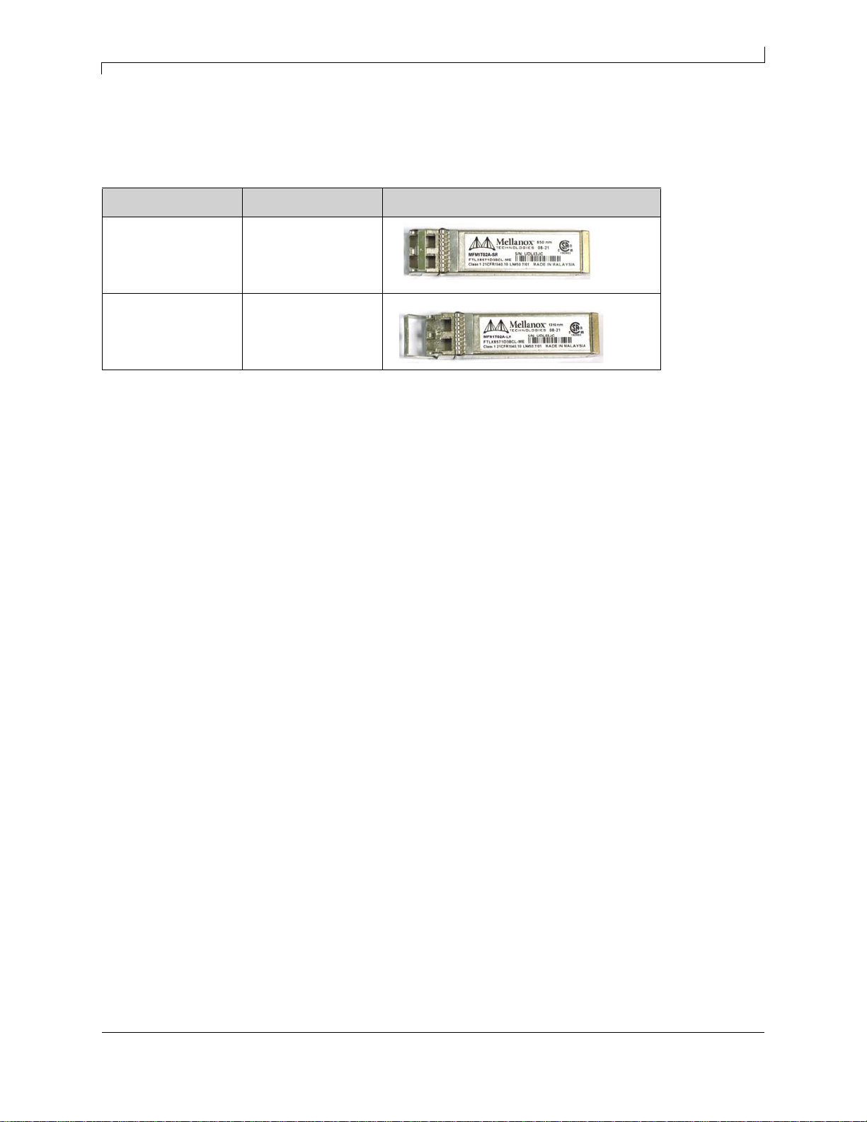
The MNPH Ethernet adapter cards are not shipped with modules. These modules must be purchased separately from
Mellanox Technologies. The Ordering Part Numbers for the Mellanox SFP+ optical modules are shown in the table
below.
Note: SR and LR modules not recommended by Mellanox may not work with the adapter.
Figure 1: SFP+ Optical Module
Spec Model number Module
10GBASE-SR MFM1T02A-SR
10GBASE-LR MFM1T02A-LRM

ConnectX EN Dual Port Ethernet Network Interface Cards With PCI Express x8 User’s Manual 11
Rev 1.4
Mellanox Technologies
1.2 Mellanox Part Numbering Legend
Table 2 describes the Mellanox Technologies adapter cards part numbering legend.
For example, the part number MNPH28-XTC describes Mellanox Technologies’ ConnectX®EN NIC with dual
10GBASE-SR/LR ports, a PCIe2.0 x8 2.5GT/s interface, no on-board memory (mem-free), a tall PCI bracket, and
RoHS R5 compliance. Using the legend,
field M = M to indicate a Mellanox Technologies product,
field H = N to indicate a Network Interface Card,
field T = P to indicate SFP+, Module-less Card,
field S = H to indicate the ConnectX family,
field # = 2 to indicate two ports,
field I = 8 to indicate PCI Express 2.0 x8 running at 2.5GT/s,
field G =B to indicate 2nd generation board,
field X = X to indicate no on-board memory,
field B = T to indicate a tall bracket, and
field R = C to indicate RoHS R5 (w/ Exemptions) compliance
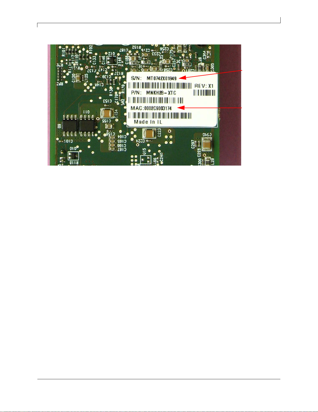
1.3 Finding the Mac Address and Serial Number on the Adapter Card
All Mellanox Ethernet NICs have a label on the printed side of the adapter card that has the card serial number and
the card MAC address.
Table 2 - Mellanox Adapter Cards Part Numbering Key
Adapter Card
OPN
MHTS#I-XBR Field Decoder
M Mellanox
Technologies
H Adapter Type H = InfiniBand Host Channel Adapter, N = Ethernet Network Interface Card, S = Express
Module
T Media E = 10GBASE-CX4*, G = 10GBASE-CX4*, K = 10GBASE-SR (XFP),
T = 10GBASE- UTP (Twisted Pair), P = 10GBASE-SR/LR (SFP+) Module-Less,
M = 10GBASE-SR/LR (SFP+) Requiring Modules
* = with powered connector
S Silicon H = ConnectX
# # ports 1 = 1, 2 = 2,
I Host Interface 8 = PCIe x8, 9 = PCIe (SerDes @ 5.0 GT/s)
G Generation <blank> = Initial product generation B = 2nd Generation board
- Separator
X Memory Size X = MemFree
B Bracket S = Short, T = Tall, N = None
R RoHS <blank> = non RoHS, C = RoHS w/ Exemption, R = RoHS Lead-Free
12
Rev 1.4 Mellanox Technologies
Figure 2: Product Label
Serial
number
MAC
address

ConnectX EN Dual Port Ethernet Network Interface Cards With PCI Express x8 User’s Manual 13
Rev 1.4
Mellanox Technologies
2 Adapter Card Installation
2.1 Hardware and Software Requirements
Before installing the NIC, please make sure that the system meets the hardware and software requirements listed in
Table 3.
2.2 Installation Instructions
2.2.1 Installation Instructions as per Host Machine
The adapter cards listed in Table 1 on page 9 are standard PCI Express x8 cards each with a standard x8 edge connec-
tor. Please consult the host machine documentation for instructions on how to install a PCI Express card.
Note: When more than one PCI Slot is available first make sure to use the PCI slot with the proper configu-
ration.
Any PCI slot with the proper configuration is acceptable for connection. If the card is installed in a PCI slot with less
lanes than the card requires then the adapter card will not provide the optimum data transfer.
Table 3 - Hardware and Software Requirements
Requirement Description
Hardware • Minimum 3 GB of available space
• PCI Express x8 or x16 slots
Firmware and
Software
Operating
Systems/Distributions
For the latest firmware available please check
http://www.mellanox.com/support/firmware_download.php
Management Tools and Drivers
Mellanox management tools can be found at:
http://www.mellanox.com/products/management_tools.php
• Linux Driver for ConnectX EN Based Network Interface Cards with 10GigE Sup-
port can be found at:
http://www.mellanox.com/products/MLNX_Linux.php
• Windows Driver for ConnectX EN Based Network Interface Cards with 10GigE.
Support can be found at:
http://www.mellanox.com/products/MTNIC%20_Windows.php
• Mellanox Ethernet Driver for Citrix XenServer 4.1, Mellanox ConnectX EN
10GbE Dual port NIC Support can be found at:
http://www.mellanox.com/products/XenServer.php
• Novell SuSE Linux Enterprise server (SLES), Red Hat Enterprise Linux (RHEL),
and other Linux distributions
• Microsoft Windows Server2003/2008, Windows Compute Cluster Server 2003
14
Rev 1.4 Mellanox Technologies
2.3 Safety Warnings
1. Installation Instructions
2. Over-temperature
3. During Lightning - Electrical Hazard
4. Equipment Installation
5. Equipment Disposal
6. Local and National Electrical Codes
7. Hazardous Radiation Exposure
Read all installation instructions before connecting the equipment to the power source.
This equipment should not be operated in an area with an ambient temperature exceed-
ing the maximum recommended:55°C (131°F). An air flow of 200LFM at this maxi-
mum ambient temperature is required. Moreover, to guarantee proper air flow, allow at
least 8cm (3 inches) of clearance around the ventilation openings.
During periods of lightning activity, do not work on the equipment or connect or dis-
connect cables.
This equipment should be installed, replaced, or serviced only by trained and qualified
personnel.
Disposal of this equipment should be in accordance to all national laws and regula-
tions.
This equipment should be installed in compliance with local and national electrical
codes.
Caution – Use of controls or adjustment or performance of procedures other than those
specified herein may result in hazardous radiation exposure.
CLASS 1 LASER PRODUCT and reference to the most recent laser standards:
IEC 60 825-1:1993 + A1:1997 + A2:2001 and EN 60825-1:1994+A1:1996+ A2:2001

ConnectX EN Dual Port Ethernet Network Interface Cards With PCI Express x8 User’s Manual 15
Rev 1.4
Mellanox Technologies
3 Driver Software and Firmware
Drivers and Firmware can be downloaded and installed by using the Mellanox download site within the Mellanox
Website.
Note: Make sure to open the Readme files and read them before you start the procedure.
Note: The installation requires administrator privileges on the target machine.
3.1 Driver Software
Mellanox Technologies supplies drivers for:
• CX EN Linux
• CX EN Windows
•VMware
•XEN
3.1.1 Driver Installation
1. Download the driver from Mellanox website
http://www.mellanox.com/products/software.php
2. Install the driver:
>tar xzf mlnx_en-X.X.tgz –
>cd mlnx_en-X.X
>./install.sh
The driver installation procedure performs the following:
• Uninstalls previous version of mlnx_en or mtnic driver
• Builds and installs driver kernel modules
– Copies all files to /tmp/mlnx_en/src
– Applies backport patches for particular kernel/OS
– Runs make to generate mlx4_core.ko, mlx4_en.ko
– Copies them to /lib/modules/<kernel>/updates/kernel/drivers/net/mlx4/
– Puts mlxnet script under /etc/init.d
– Puts mlxnet.conf under /etc/mlxethernet
• Builds and installs mstflint FW burning tool
• Optimizes system settings for best network performance
3.1.2 Driver Loading
• Always use /etc/init.d/mlxnet script to load/unload the driver:
> /etc/init.d/mlxnet start
• Automatic driver loading on boot.

16
Rev 1.4 Mellanox Technologies
Edit /etc/mlxethernet/mlxnet.conf
• Change driver default settings.
Module parameters can be obtained with ‘modinfo’ command:
Add custom parameter settings to /etc/modprobe.conf
Parameter values are available in /sys/module/mlx4_en/parameters/
• Verify driver loaded successfully.
Driver will create new eth<x> device(s) visible with ‘ifconfig –a’
3.1.3 Driver Information
• Dumped to system log (/var/log/messages, dmesg)
• Can also be queried by ‘ethtool –i eth<x>’
3.2 Firmware and Firmware Tools
For Linux or Windows, download and install the latest Mellanox Firmware Tool Kit for your OS at:
http://www.mellanox.com/products/management_tools.php
Within the tool kit is the mtsflint tool software package, which is also available at:
https://svn.openfabrics.org/svn/openib/gen2/branches/1.1/src/userspace/mstflint/.
You can download the latest firmware at:
http://www.mellanox.com/support/firmware_table_ConnectXEN.php
Follow the installation instructions included in the download package.
3.2.1 Updating Adapter Card Firmware
Each adapter card is shipped with the latest version of qualified firmware at the time of manufacturing. Firmware is
updated occasionally, and the most recent firmware can be obtained from http://www.mellanox.com through the
‘Firmware’ downloads link, or you can download the latest firmware at:
http://www.mellanox.com/support/firmware_table_ConnectXEN.php.
3.2.2 Single Adapter Card Firmware Update
Firmware can be updated on the stand-alone single card using the flint tool of the Mellanox Firmware Tools (MFT)
package. This package is available for download, along with its user’s manual, from the single adapter card firmware
update page. See http://www.mellanox.com under ‘Firmware’ downloads.
A firmware binaries table lists a binary file per adapter card. The file name of each such binary is composed by com-
bining the firmware name, the firmware release version, and the card part number.
Note: Please contact your assigned Field Application Engineer if you cannot find the firmware binary for
your adapter card. This may happen if the product is not yet available for general distribution.
3.2.3 Firmware Version Check and Update
1. Check current FW version and card type (MT_xxxxxxxxxx).
ethtool -i eth<x> or
mstflint –d `lspci | grep “Ethernet controller: Mellanox” | cut -f1 -d" “` q
mstflint tool is provided in the driver package and is normally installed under /sbin
2. Obtain the latest FW image from Mellanox web site.
http://www.mellanox.com/support/firmware_table_ConnectXEN.php

ConnectX EN Dual Port Ethernet Network Interface Cards With PCI Express x8 User’s Manual 17
Rev 1.4
Mellanox Technologies
3. Choose FW image matching you card OPN/PSID.
4. Burn latest FW.
mstflint –d `lspci | grep “Ethernet controller: Mellanox” | cut -f1 -d" “` -i <FW image> b
Where FW image is a binary file, for example fw-25408-2_5_000-MNEH28-XTC_A1.bin
5. Reboot the server.

18
Rev 1.4 Mellanox Technologies
4 Adapter Card Interfaces
4.1 I/O Interfaces
Each adapter card includes the following interfaces:
• PCI Express x8 edge connector
• I/O panel LEDs
•I
2C compatible connector (for debug)
4.1.1 PCI Express Interface
The ConnectX®EN adapter cards support the PCI Express 2.0 x8 interface, 1.1 compatible. The NICs can be either a
master initiating the PCI Express bus operations or a slave responding to PCI bus operations.
4.1.2 LED Assignment
The board has four LEDs located on the I/O panel - 2 LEDs per port. The green LED, when lit, indicates that the
driver is running and a valid physical connection between nodes exists. The green LED, when blinking, indicates that
the physical connection between nodes is problematic. The yellow LED when lit, indicates a valid data activity link,
this is the logical link. The yellow LED illuminates when the network is discovered over the physical link. A valid
data activity link without data transfer is designated by a constant yellow LED indication. A valid data activity link
with data transfer is designated by a blinking yellow LED indication. If the LEDs are not active, either the physical
link or the logical link (or both) connections have not been established.
Figure 3: Physical and Logical Link Indications
Note: The short bracket has the same port and LED footprint as the tall bracket.
Port 1
Port 2
Port Number LED Name
Port 1 Physical Link - Green
Constant on indicates a good physical link
Blinking indicates a problem with the Physical link
Data Activity - Yellow
Blinking indicates Data Transfer
Constant on indicates no Data Transfer
Port 2 Physical Link - Green
Constant on indicates a good physical link
Blinking indicates a problem with the Physical link
Data Activity - Yellow
Blinking indicates Data Transfer
Constant on indicates no Data Transfer

ConnectX EN Dual Port Ethernet Network Interface Cards With PCI Express x8 User’s Manual 19
Rev 1.4
Mellanox Technologies
4.2 I2C Compatible Interface
A three-pin header on the adapter card is provided as the I2C compatible interface. See Figure 1 on page 23 for the
location on the board.
Figure 4: I2C Connector
4.3 Power
All adapter cards receive power from the PCI Express Edge connector. All other required power voltages are gener-
ated by on-board switch mode regulators. For power consumption see Specifications starting on page 23.
4.4 Memory
The NICs support multiple memory devices through the PCI Express, Flash, and I2C-compatible interfaces.
4.4.1 System Memory
Each of the NICs utilize the PCI Express interface to store and access connection information and packet data on the
system memory.
4.4.2 Flash
Each of the NICs includes one 2MB SPI Flash device (P/N M25P16-VME6G by ST Microelectronics) accessible via
the Flash interface of the MT25408 ConnectX EN device.
There is a jumper on each adapter card that indicates to the device whether an on-board Flash device exists (or is to be
used). Table 4 provides information on this jumper. See Figure 1 on page 23 for the jumper location.
4.4.3 EEPROM
Each board incorporates an EEPROM that is accessible through the I2C-compatible interface. The EEPROM is used
for storing the Vital Product Data (VPD). The VPD format adheres to the PCI Local Bus specification rev 2.3 VPD
definition (see “VPDs” on page 20). The EEPROM capacity is 512 bytes.
Table 4 - Jumper Configuration
Description Option Card Default
Configuration Comments
Flash present/ not present connection open – Flash present
connection shorted – Flash not present connection open
– Flash present Header 1x2

20
Rev 1.4 Mellanox Technologies
4.5 VPDs
The PCI VPD (Vital Product Data) layout for each of the described Mellanox Technologies ConnectX®EN cards
comply with the format defined in the PCI 2.3.
PCI VPD Layout for MNPH28B-X[ST]C
Table 5 - VPD layout for MNPH28B-X[ST]C
Offset
(Decimal) Item Value Format Description
0 Large Resource Type ID String Tag (0x02) 0x82
1 Length [7:0] LSB 0xE
2 Length [15:8] MSB 0x0
3 Data Hawk Dual
Port STR
17 Large Resource Type VPD-R Tag (0x10) 0x90
18 Length [7:0] LSB 0x4F
19 Length [15:8] MSB 0x00
20 VPD Keyword PN STR Add in Card Part Number
22 Length 0x15
23 PN PN %STR_SPC
44 VPD Keyword EC STR Engineering Change Level of the card (rev)
46 Length 0x2
47 Revision RV %STR PCB revision
49 VPD Keyword SN STR Serial Number
51 Length 0x18
52 SerialNumber %STR_SPC “00..00XXXX..XX”
76 VPD Keyword V0 STR Misc. Information
78 Length 0x10
79 Data PCIe x8 STR_SPC
95 VPD Keyword RV STR
97 Length 0x1
98 Data 0,97 %CS0
99 Large Resource Type VPD-W Tag (0x11) 0x91
100 Length [7:0] LSB 0x99
101 Length [15:8] MSB 0x00
102 VPD Keyword V1 STR EFI Driver version
104 Length 0x6
105 Data N/A STR_SPC
111 VPD Keyword YA STR Asset Tag
113 Length 0x20
114 Data N/A STR_SPC “N/A”
146 VPD Keyword RW STR Remaining read/write area
148 Length 0x6A
149 Data STR_ZERO Reserved (0x00)
255 Small Resource Type END Tag (0x11) 0x78
This manual suits for next models
4
Table of contents


