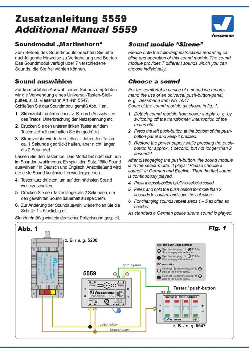
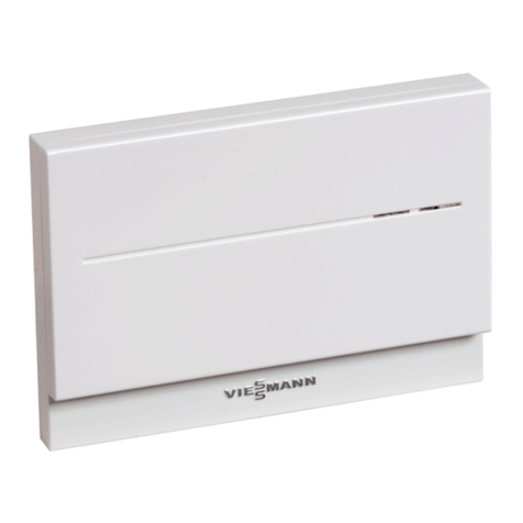
Viessmann 5556 User manual

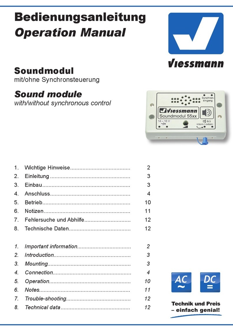
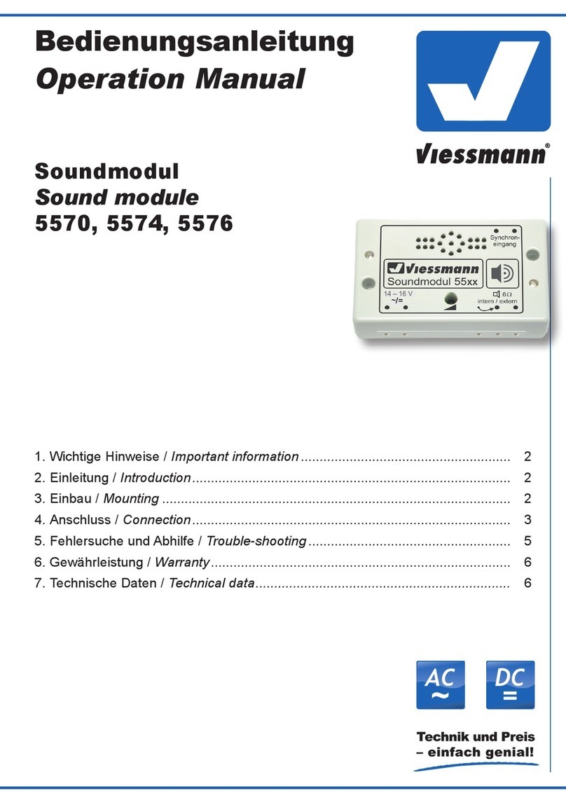
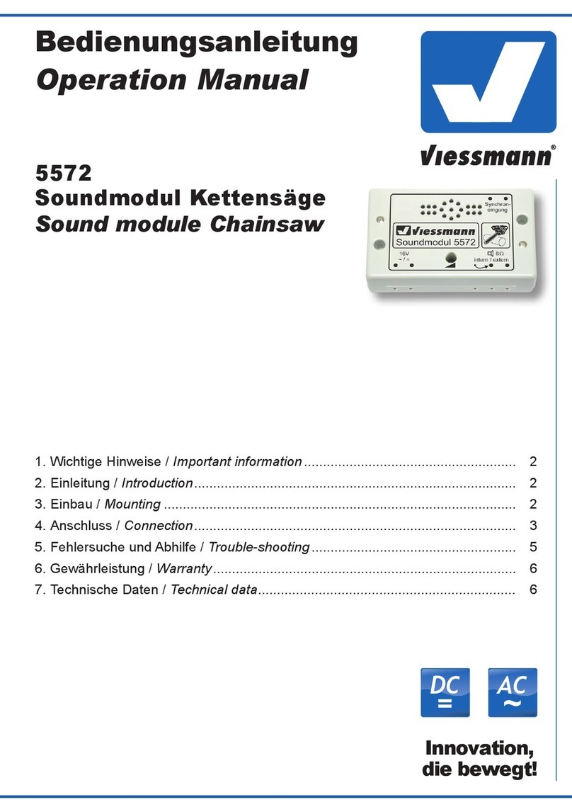
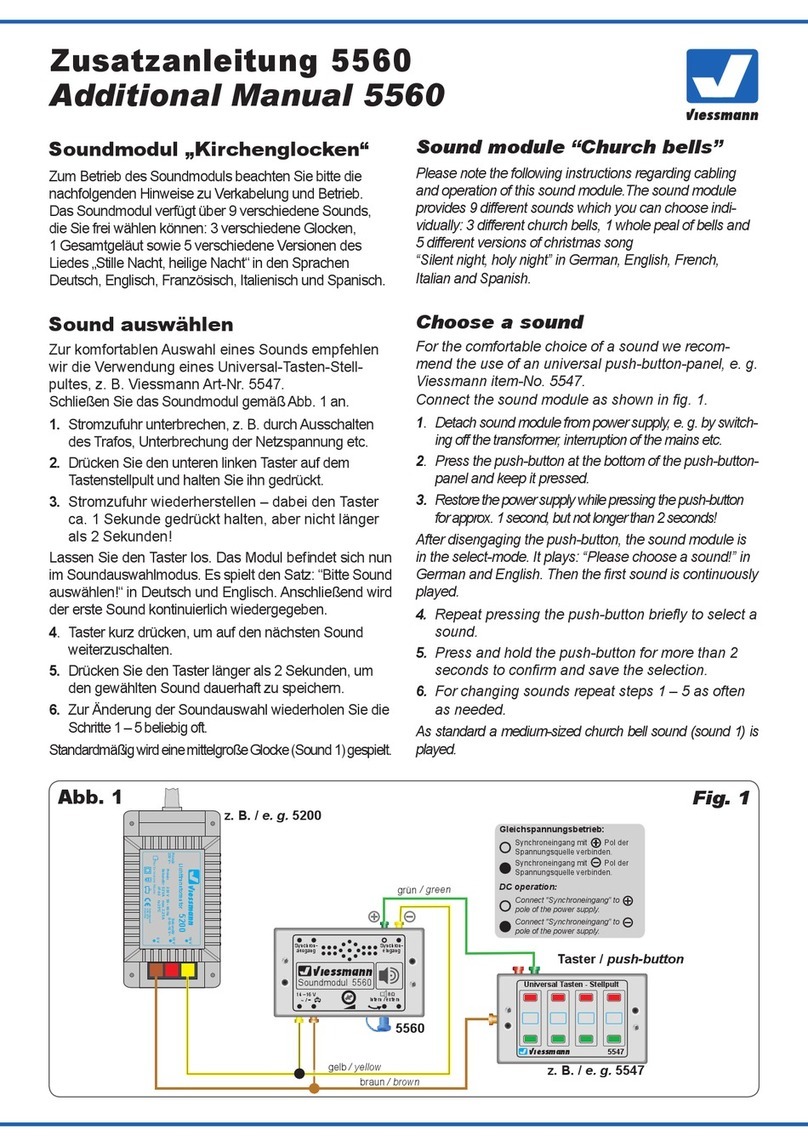
Bedienungsanleitung
Operation Manual
5556
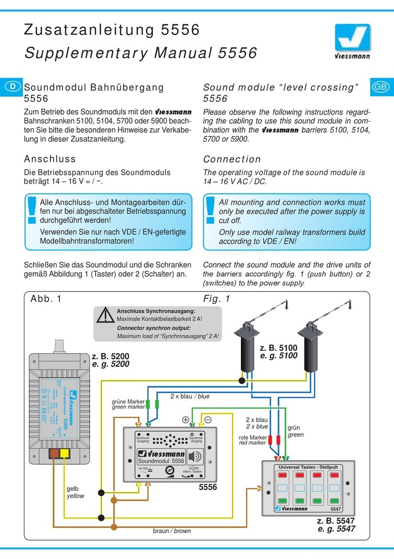
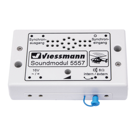
Soundmodul Bahnübergang
Sound module level crossing
1. Wichtige Hinweise / Important information ................................................ 2
2. Einleitung / Introduction ............................................................................. 3
3. Einbau / Mounting...................................................................................... 3
4. Anschluss / Connection ............................................................................. 4
5. Betrieb / Operation .................................................................................... 6
6. Fehlersuche und Abhilfe / Trouble-shooting.............................................. 11
7. Gewährleistung / Warranty ........................................................................ 12
8. Technische Daten / Technical data ........................................................... 12
AC
~
DC
=

2
DE EN
1. Wichtige Hinweise
Bitte lesen Sie vor der ersten Anwendung des Pro-
duktes bzw. dessen Einbau diese Bedienungsanlei-
tung aufmerksam durch. Bewahren Sie diese auf,
sie ist Teil des Produktes.
1.1 Sicherheitshinweise
Vorsicht:
Verletzungsgefahr!
Für die Montage sind Werkzeuge nötig.
Stromschlaggefahr!
Die Anschlussdrähte niemals in eine Steckdo-
se einführen! Verwendetes Versorgungsgerät
(Transformator, Netzteil) regelmäßig auf Schä-
den überprüfen. Bei Schäden am Versorgungs-
gerät dieses keinesfalls benutzen!
Alle Anschluss- und Montagearbeiten nur bei ab-
geschalteter Betriebsspannung durchführen!
Ausschließlich nach VDE/EN-gefertigte Modell-
bahntransformatoren verwenden!
Stromquellen unbedingt so absichern, dass es
bei einem Kurzschluss nicht zum Kabelbrand
kommen kann.
1.2 Das Produkt richtig verwenden
Dieses Produkt ist bestimmt:
- Zum Einbau in Modelleisenbahnanlagen und
Dioramen.
- Zum Anschluss an einen Modellbahntransforma-
tor (z. B. Art. 5200) bzw. an einer Modellbahn-
steuerung mit zugelassener Betriebsspannung.
- Zum Betrieb in trockenen Räumen.
Jeder darüber hinausgehende Gebrauch gilt als
nicht bestimmungsgemäß. Für daraus resultieren-
de Schäden haftet der Hersteller nicht.
1.3 Packungsinhalt überprüfen
Kontrollieren Sie den Lieferumfang auf Vollstän-
digkeit:
- Soundmodul
- 2 Schrauben
- 6 Stecker
- Anleitung
1. Important information
Please read this manual completely and attentively
before using the product for the rst time. Keep this
manual. It is part of the product.
1.1 Safety instructions
Caution:
Risk of injury!
Tools are required for installation.
Electrical hazard!
Never put the connecting wires into a power sock-
et! Regularly examine the transformer for damage.
In case of any damage, do not use the trans-
former.
Make sure that the power supply is switched o
when you mount the device and connect the ca-
bles!
Only use VDE/EN tested special model train
transformers for the power supply!
The power sources must be protected to prevent
the risk of burning cables.
1.2 Using the product for its correct purpose
This product is intended:
- For installation in model train layouts and diora-
mas.
- For connection to an authorized model train
transformer (e. g. item 5200) or a digital com-
mand station.
- For operation in dry rooms only.
Using the product for any other purpose is not ap-
proved and is considered inappropriate. The man-
ufacturer is not responsible for any damage result-
ing from the improper use of this product.
1.3 Checking the package contents
Check the contents of the package for complete-
ness:
- Sound module
- 2 screws
- 6 plugs
- Manual

3
Einbaulage für Soundmodule
Mounting of sound modules
Lautsprecherschlitze nicht abdecken!
Mit Lautsprecher nach oben montieren!
Do not cover loudspeaker slots!
Mount the module with loudspeaker on top!
Falsch RichtigFalsch
wrong correctwrong
Optimal
ideal
Fig. 1
Abb. 1
2. Einleitung
Genießen Sie die Modellwelt mit allen Sinnen.
Noch lebendiger werden Modellbahnen und
Dioramen mit passender Geräuschkulisse.
Viessmann Soundmodule sind mit Geräuschen
für verschiedene Themen erhältlich. Sie sind dank
ihres eingebauten Lautsprechers einfach zu in-
stallieren, sehr kompakt und sofort betriebsbereit.
Die Lautstärke sowie die Wiedergabedauer sind
selbstverständlich regelbar. Die auf den Modulen
enthaltenen Geräusche sind fest installiert und nicht
austauschbar.
2.1 Synchronsteuerung
Dieses Modul verfügt über einen Steuerausgang
und erzeugt bewegungssynchrone Sounds passend
zu geeigneten Bahnschranken.
3. Einbau
Die Befestigung des Bausteins erfolgt mit den bei-
liegenden Schrauben. Für optimalen Klang beach-
ten Sie folgende Hinweise:
1. Der Lautsprecher ist im Modul integriert. Für eine
gute Schallverteilung darf die Oberseite des Mo-
duls nicht verdeckt sein.
2. Soundmodul möglichst in Richtung der Zu-
schauer/Zuhörer ausrichten, also keine
Über-Kopf-Montage unter der Anlage.
3. Das Soundmodul sollte sich dort benden, wo
das entsprechende Funktionsmodell auf Ihrer An-
lage vorkommt. Sie können das Modul auch auf
der Anlage (z. B. in einem Gebäude etc.) einbau-
en. So erreichen Sie noch besseren Klang und
eine bessere Übereinstimmung von sichtbarer
und hörbarer Geräuschquelle.
2. Introduction
Enjoy the model world with all your senses. Model
train layouts and dioramas become even more re-
alistic and alive with the appropriate background
sound.
Viessmann sound modules are available with
sounds tting for dierent subjects. They are very
compact, immediately operational and easy to in-
stall due to the integrated loudspeaker. Of course,
the volume can be adjusted. The sounds of the
modules are an integrated part and cannot be
exchanged.
2.1 Synchronized control
The module is equipped with a control output so
that it can generate motion synchronized sounds
suitable for the respective level crossings.
3. Mounting
Fix the module with the enclosed screws. To en-
sure an optimal sound reproduction of the module,
please note the following tips:
1. The loudspeaker is an integrated part of the
module. The upper surface of the module must
always be uncovered in order to enable a good
sound dispersion.
2. The sound module must always be adjusted to the
direction of the spectator, so please no upside down
mounting under the layout.
3. The sound module should be installed close to the
respective functional model on your layout. You can
also install the module on the layout, e. g. in a build-
ing. This way you can achieve a better sound and an
optimal concordance between the visible and the au-
dible sound source.

4
4. Anschluss
Geeignete Kabel: Der geringe Strombedarf des
Soundmoduls erlaubt es, entsprechend klein di-
mensionierte Kabel, die sich gut versteckt verlegen
lassen, zu verwenden. Wir empfehlen Litze mit ei-
nem Querschnitt von 0,14 mm² (z. B. Viessmann
Art. 6860 – 6869 oder 68603 – 68693).
4.1 Anschluss des Synchronausgangs
Von diesem Soundmodul werden die Schranken
und weitere Module angesteuert. Beachten Sie bit-
te die folgenden Abbildungen:
Soundmodul Art. 5556 an Art. 5100, 5700, oder
5900 (Abb. 2), Soundmodul Art. 5556 an Art. 5104
oder 5107 (Abb. 3).
Zum Ein- und Ausschalten der Modelle (Art. 5100,
5700, 5900) sowie des Soundmoduls benötigen
Sie einen Schalter oder Taster, der an den Buchsen
„Synchroneingang“ angeschlossen ist. Viessmann
empehlt hierzu den Universal-Ein-Aus-Umschalter
Art. 5550 oder das Tasten-Stellpult, 2-begrig Art.
5547. Wenn gemäß Abb. 5 auch Module wie das
einfache Andreaskreuz Art. 5065 geschaltet werden
sollen, dann verwenden Sie Art. 5550.
4. Connection
Fitting cables: Due to the low current consump-
tion thin cables can be used which can easily be
hidden. It is recommended to use a cross section
of 0,14 mm² (e. g. Viessmann item 6860 – 6869 or
68603 – 68693).
4.1 Connection of the synchronized output
This sound module triggers the barriers and other
modules. Therefore, it is necessary to consider the
corresponding gures:
Sound module item 5556 to item 5100, 5700 or
5900 (g. 2), sound module item 5556 to item 5104
or 5107 (g. 3).
You need a switch or a push button to operate the
models (item 5100, 5700, 5900) as well as the
sound module. The switch is connected to the con-
nection sockets “synchronous input”. Viessmann
recommends the universal on-o switch item 5550
or the push button panel 2-aspect item 5547. If you
want to switch modules such as the simple St. An-
drew’s cross item 5065 (as shown in g. 5), you
should use item 5550.
Sekundär
0-10-16 V~
16 V
Primär
230 V~
Gefertigt nach
VDE 0570
EN 61558
Lichttransformator
5200
Nur für trockene Räume
Primär 230 V 50 - 60 Hz
Sekundär max. 3,25 A52 VA
ta 25°CIP 40
10 V
0 V
viessmann
5550
Universal Ein-Aus-Umschalter
gelb/yellow
braun/brown
z. B./e. g. 5200 z. B./e. g. 5100/5700/5900
grün/green
5556
Gleichspannungsbetrieb:
Synchroneingang mit Pol der
Spannungsquelle verbinden.
Synchroneingang mit Pol der
Spannungsquelle verbinden.
z. B./e. g.
5550/5547
DC operation:
Connect “Synchroneingang” to
pole of the power supply.
Connect “Synchroneingang” to
pole of the power supply.
blau mit roter Markierung
blue with red marking
blau mit grüner Markierung
blue with green marking
Fig. 2
Abb. 2
Anschlussschema gilt ausschließlich für Art. 5100/5700/5900 an Soundmodul Art. 5556
The wiring is only valid for items 5100/5700/5900 to sound module item 5556

5
z. B. / e. g. Commander
Commander
Sekundär
0-10-16 V~
16 V
Primär
230 V~
Gefertigtnach
VDE0570
EN61558
Lichttransformator
5200
Nur für trockene Räume
Primär 230 V 50 - 60 Hz
Sekundär max. 3,25 A52 VA
ta 25°CIP 40
10 V
0 V
z. B. / e. g. 5200
grün
orange
green
orange
viessmann
Powermodul 5215
T
E
ge bn
Braune Massebuchsen
nicht koppeln !
max. 24 V~
rt bn
zu den Decodern
5215
Positiv
positive
viessmann
4-fach-Blinkgerät 5065
16 V ~
bn
1
ge
ge
4
32
zu den Andreaskreuzen
to the St. Andrews crosses
braun / brown
gelb / yellow
Decoder 5104
grün / green
orange / orange
blau / blue
330 Ohm
0,25 W
Geschwindigkeit:
Originalstand: 6 sec
Nach dem Schnitt: 3 sec
Barrier speed:
Original: 6 sec
After cutting the wire: 3 sec
Tasten-Stellpult 2-begriffig
5547
Viessmann
grüne Markierung
green marking
rote Markierung
red marking
braun
brown
blau / blue
blau / blue
orange / orange
grün / green
braun / brown
gelb / yellow
braun / brown
gelb / yellow
braun / brown
gelb / yellow
10 - 16 V AC ~
14 - 24 V DC =
Anschluss möglich an Schaltzentrale oder Trafo
Connection is possible to digital station or transformer
Fig. 3
Abb. 3
z. B. / e. g. 5104, 5107
Anschlusschema gilt ausschließlich für Art. 5104/5107 an Soundmodul Art. 5556
The wiring is only valid for item 5104/5107 to sound module item 5556
Other manuals for 5556
2
Table of contents
Other Viessmann Recording Equipment manuals

Viessmann
Viessmann 5556 User manual

Viessmann
Viessmann 5574 User manual

Viessmann
Viessmann 55 Series User manual

Viessmann
Viessmann 5560 User manual

Viessmann
Viessmann 5559 User manual

Viessmann
Viessmann 5574 User manual

Viessmann
Viessmann 5572 User manual

Viessmann
Viessmann 5559 Instructions and recipes

Viessmann
Viessmann VITOCONNECT OPTO2 User manual

Viessmann
Viessmann 5575 User manual