Melles Griot 13 PDC 001/IEEE User manual
Universal
Optical Power
Meter
13
PDC
OOl/IEEE
Operator's
Manual

Operator's Manual
UniversalOptical Power Meter
13
PDC
OOIAEEE
April,
1995
9072-9800
1B
Copyright
Melles
Griot.
AU
rights
reserved
4665 Nautilus Court
South
Boulder, Co. 80301
(800)326-4363 (303)581-0337
Fax
(303) 581-0960

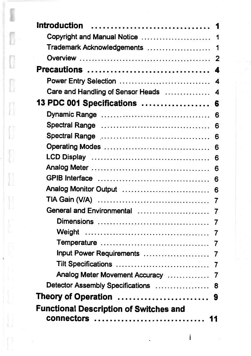
Introduction
...............................
1
.......................
CopyrightandManual Notice
1
.....................
TrademarkAcknowledgements
1
...........................................
Overview 2
................................
Precautions
4
..............................
Power EntrySelection
4
...............
Careand Handlingof Sensor Heads
4
..................
13
PDC
001
Specifications
6
....................................
Dynamic Range
6
....................................
Spectral Range
6
.....................................
Spectral Range
6
...................................
OperatingModes
6
.......................................
LCD Display
6
.......................................
Analog Meter
6
.....................................
GPlB Interface
6
.............................
AnalogMonitorOutput
6
TIAGain(VIA)
.....................................
7
GeneralandEnvironmental
........................
7
Dimensions
.....................................
7
Weight
.........................................
7
Temperature
....................................
7
Input Power Requirements
......................
7
Tilt Specifications
...............................
7
Analog Meter MovementAccuracy
..............
7
..................
DetectorAssembly Specifications
8
........................
Theory
of
Operation
9
FunctionalDescriptionof Switchesand
.............................
connectors
I
I

FrontPanel
.......................................
11
MeterZero
.....................................
11
NULL
..........................................
11
Range
.........................................
11
Setup
..........................................
11
....................
LEFTIRIGHT
Arrow
Key
(a)
12
UPArrowKey(-)
...............................
12
DOWNArrow Key
C)
..........................
12
Rear Panel
........................................
12
.....
CalibratedPhotodetectorHeadConnector 12
......
....................
IEEE-488Connector
:
12
...................
A.C. InputPower Connector 12
A.C. Power Selector
...........................
12
.................
BNCAnalog Output Connector 12
System Operation
-
Front Panel Keys
......
13
Introduction
.......................................
13
FactoryDefaultPower-Up
.........................
13
......
UnitSerial Number. Revision. andErrors 13
......
Connected DetectorStatus
&
Information 14
Default Power-Up MainDisplay
...................
15
................
Additional ExternalAttenuation 15
ExternalFilterStatus
...........................
16
NULL
..........................................
16
IEEE-488Status
...............................
17
Analog MeterType
............................
18
.....
Rear PanelBNC Output Transfer Function 18
.........................
WavelengthIndication 19
ElectricalBandwidth Filter Indication
...........
19

..........
Display MeasurementUnits Indicator
20
Display MeasurementType lndicato
...........
20
................................
Range Indicator 20
..............................
IndicatorUpdates 21
...................
.......
Range Control
..
22
..............................
Overrangecondition 22
.............................
Underrangecondition 22
..................................
RangeSelection 23
........................
FrontPanelRangeKey 23
.................
SelectingAuto or FixedRange 24
.........................
Fixed RangeSelection 24
.........
MinimumandMaximumFixedRanges 26
.............
FixedRangeFrequency Response 26
Setup
.....................................
27
................................
MainSetup Screen 27
..................................
Display Menu 28
........................
Wavelength Reference 31
..........................
OpticalFilterINIOUT 32
..............
Additional Beam PathAttenuation 32
...............
Electrical(A.C.) BandwidthLimit 33
........
Saving
&
Recalling13PDC 001 setups
34
....................
Analog MeterDisplayMode
36
...................
Display BacklightingControl
38
Display LCDForeground/Background
.....
38
................................
Control
.........
IEEE488
Communication Parameters 39
...........................
Status
&
Information 40
.......................
IEEE-488
Operation
42
iii

...............................
IEEE-488
Overview
42
...........................
Command structures
42
..............
On-Screen Troubleshooting Help
43
.......................
13
PDC
001
Commands
44
................
9.1.4.
SCPl Status Commands
45
9.1.5.
MeasurementCommands
..............
46
......
9.1.6.
Configuration Control Commands
47
........
9.1.7.
User DefinedSensor Calibration
50
9.1.8.
Triggered Operation
....................
52
9.1.9.
Data Buffer Retrieval
....................
52
13
PDC
001
ErrorCodes
...................
54
Suggestions on Power Measurement
......
56
Appendices
...............................
58
Warranty Statement
...............................
58
Calibration Services
...............................
58
Service and Repairs
...............................
58
Sales Service and Technical Support Centers
.....
61

I.
Introduction
1
.I
Copyrightand Manual Notice
This manual describesthe operation of theMelles GriotUniversal
OpticalPower Meter System. Melles Griotreserves the right to
make changesto this manual and to the equipment described herein
without notice. MellesGriot has made considerable effortsto
ensurethat the information in this manual is accurateand complete.
However, Melles Griot
will
not be liablefor
any
technicalor
editorialerrors or omissionsmade herein orforincidental, special,
orconsequentialdamages of any nature resulting fiomthe
hrnishing of this manual, or operation and performance of
equipment in connectionwith this manual.
0
Copyright
1995
by MellesGriot, Inc..
All
RightsReserved.
I
.2
TrademarkAcknowledgements
MELLES GRIOTQ is a registered trademark ofMelles Griot, Inc.
inthe United StatesofAmerica and certain other countries. In
France,
Germany,
Italy, Belgium, TheNetherlands, and
Luxembourg,MEUESGRIOTQis a registered trademark of
Melles Griot
B.V.
All
other product names and company names aretrademarksand
registered trademarks of other manufhcturers.
m81l5
-9072-98001B pg.
1

1.3
Overview
IWlZURATlNO
WHERE
~DRA'lW~
IPHm
51
ISPDHWI
91
1SPMOD6
EU
13PDH003
GE
13POHlOl
0E
1SPDHlO6
GI
13PDHIOQ
(4
amDcooa
--
mR
-
VII)
--.
1.3.0.1
--
13
PDC
001
Control Unit and
Detector
Assemblies
The Melles Griot
13
Universal OpticalPower Meteris a
versatile, microprocessordriven controlunit that operates
in
conjunctionwith a variety of detectorassembliesasillustrated
in
figure
1.3.O.
1.
The control
unit
supportsdetectors
with
responsivitiesbetween
300
and
2000
nrn
and
can
measurepower
levelsfrom
5
picowattsto
2
watts. The associated detector
assemblies
are
equipped
with
a cableresident programmable
memory that storescalibrationcoefficients necessary to achievethe
absoluteaccuracy from assemblyto assembly. When the detector
cable isattached tothe controlunit, the calibrationdata is
automaticallyread by themicroprocessor
and
all power
measurementsare adjusted forthe unique response characteristics
of
an individual
detectorassembly. Themeter provides setupmenus
and
data readout through a
64
x
192
pixel, electro-luminescent

backlit Liquid CrystalDisplay (LCD) and
six
fiontpanel selection
buttons.
The
instrumentmeasures and computessignalAverage,
true
RMS,
AC coupled true
RMS,
Peak, and Peak-to-Peak.
Measurementsmay be displayed in units of watts,
dBm,
or detector
current.
An
illuminated needle meter providesinstantaneous
feedbackof percent modulation or percent deviation of signal
average. Thisfeatureis valuable fortuning lasersand for optimizing
thethroughput of fiber coupled systems. The 13PDC 001 comes
equipped with a calibrated analog outputand
also
has an optional
IEEE
488.2 communications/controlinMce.
All
functions and
data are programmablethroughthis interface. TheUniversal
OpticalPower Meter is packaged in a compact enclosurethat easily
tilts and holdsbetween -20 degrees and +20 degreestothe
horizontal. The unit
has
provisionsfor input power operationfiom
90-125VAC and 200-24OVAC.
Sixprimary detectorconfigurationsare available. Silicon
(400-
1
100
nrn)
and germanium detectors(800-1800
nm)
are
availablein one of three calibrated configurations,a bare detector
assembly,
with
a 50mm integrating sphere, and with a 152mm
integratingsphere. Thebare detector assembliesare provided
with
ND
3
attenuatingfiltersforuse at high optical power levels or at
high
opticalpower densities. The calibrationdata includes
coefficientsboth with and without the attenuator. These detector
assemblieshave a particularly convenientfeaturethat permits
storageof theattenuatorwhen not in use. Also, the detector
assembliesarecompatible
with
the popular 13DMA seriesmodular
mounting accessoriesfor photodiodes. Fiy,the
13
PDA seriesof
accessoriesprovides compatibility
with
the more common fiber
opticconnectors. These accessoriesare compatiblewith
all
of the
13PDH seriesdetectorand integrating sphereassemblies.
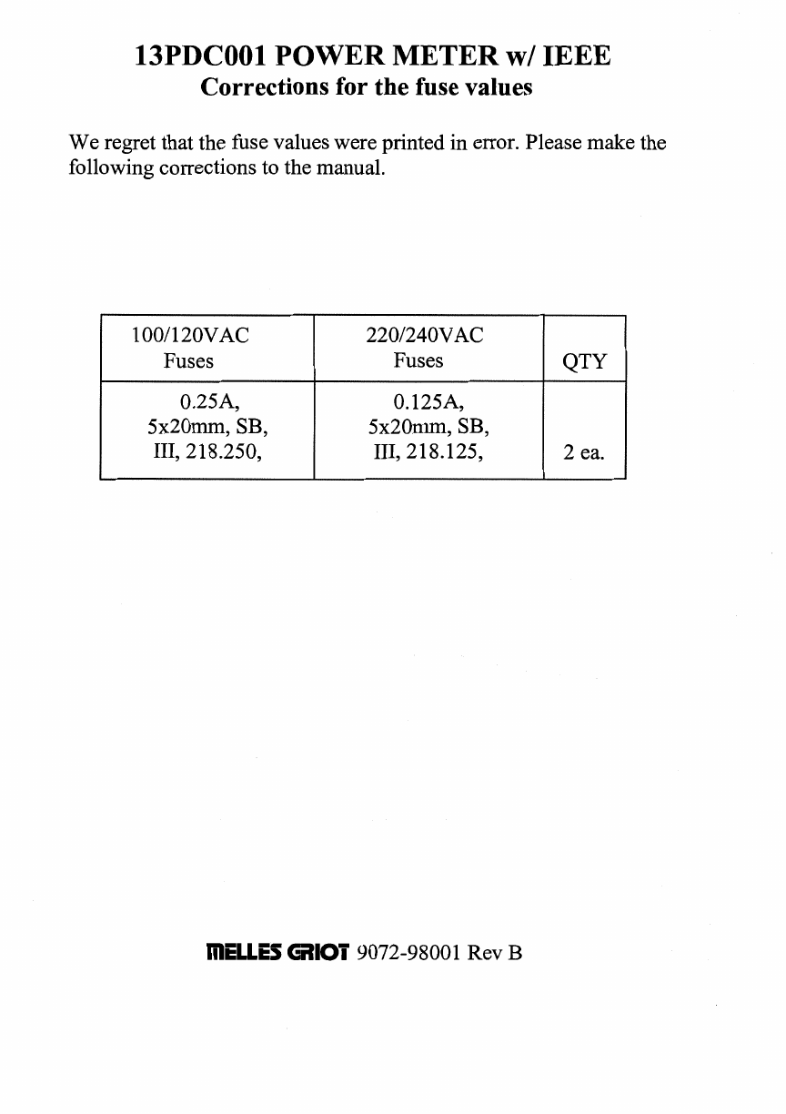
13PDCOOl
POWER
METER w/
IEEE
Corrections for the fusevalues
We regret that the fusevalues were printed in error. Pleasemake the
followingcorrectionsto the manual.
mELLES
6110i
9072-98001Rev
B
1001120VAC
Fuses
0.25A,
5x20mrn, SB,
111, 218.250,
2201240VAC
Fuses
0.125A,
5x20mm7SB,
111, 218.125,
QTY
2
ea.
2
Precautions
2.1
Power EntrySelection
The
13
PDC001
will
accept
A.C.
power inputsat 'standard
voltages' of
1
10
or
220
V
(50
or
60
Hz).
Before applyh~!
AC
power to the instrument:
1)
Install
the correct hsesforthe linevoltage being used. Two
250
mA,
and two
500
mA
hsesare supplied with the instrument. The
250
mA
fusesare foruse with
220-240
VAC
operation, and the
500
mA
fusesare foruse
with
90-120
VAC
operation.
2)
Ver@that the power entry selection switchon the rear panel of
theunit ispositioned to match your power. The selector switchis
set
by using a coin or screwdriverto
align
the correct voltage
reading
("
110v"
or
"220~")
below the arrowprinted on the selector
switchhousing.
2.2
Care and Handlingof Sensor Heads
The followingprecautions shouldbe observed when handling and
using the
13
PDH
detectorheads.
The post mountable silicon and germanium detectorheads
(13
PDH
00
1
and
101)
come equipped
with
an attenuatingfilter.
When
inserted in fiont of the detector, thesefiltersnot only help prevent
detectorsaturation,but
also
prevent
dirt
and dust fiom
accumulating on the detectorface
and
degradingthe detector's
measurement accuracy. Itis suggested that the attenuatingfilterbe
used whenever possible. Ifthepower level ofthebeam under test
requiresthe filterbe removed, it isrecommended that the filterbe
attachedto the rear side of the detectorhousing for safe storage.
After the measurement iscomplete, make sureto reattach the filter
to the entrance side of the detectorassembly. This
will
help keep
the detectorhce clean. Ifdust accumulateson the detectorface
use filtered, dry
air
to cleanit before reattaching the filter Never
touchthe detectorface
with
any object
as
permanent damagemay

occur. Fingerprintsand residuefiomcleaningfluids
will
seriously
degradethe system's
NEP.
Caremust
also
be used when
hading
the
50
mm
and
152
mm
integratingsphereldetectorcombinations
(13
PDH
003, 103,005,
and
105).
The spectralcalibrationof theintegrating spherescan be
degraded
if
the sphereis dented
as
a result of being dropped, or
if
objectsor contaminantsgetinside ofthe sphere. It isrecommended
that theintegratingsphere's input port cover be used when the
sphereisnot being used for a power measurement.
IIIBLLES
-9072-98001B
pg.
5
3.
13
PDC
001
Specifications
Dynamic Range
10-l2
W
to over
2
W
(with
ND
filter).
Spectral Range
300
nm
to
2000
nm
(selectable
in
1
nm
increments).
(Allowable
range
determined
by
calibrated
head
installed)
Operating Modes
The
13
PDC
001
will
displayreadings
in
units of watts,
dBm,
and
detector current. The instrument
will
compute signal Average, true
RMS,
AC
coupled
true
RMS,
Peak,
or Peak-to-Peak. Section
8.1.1
describesthese operatingmodes
in
detail.
(Power
ranges
only
available
with
calibrated
head
installed)
LCD
Display
64
x
192
pixel,
EL
backlit.
Power is displayed
in
4
digits.
Other
operationalinformation is
displayed
as
required.
Analog Meter
Selectable, percent deviationor percent modulation.
GPlB Interface
EEE
488.2,
SCPIcommand syntax.
Analog MonitorOutput
Level:
+1
volt nominal
&5
volt maximum (over-range)
Impedance:
lh
ScaleFactor: Displayed on LCD screen
(The
scale
factor
is
a
fimction
of
wavelength
calibration)

TIA
Gain
(VIA)
Analog
Output
Bandwidth
1
0l0 30
Hz
lo9
loo
HZ
lo8
300
Hz
1
o7
1m
1
o6
30
kHz
lo5
10
k~z
lo4
30~*
I
o3
OW*
*
(The displayed
data
in
these rangesis limited to
25KHz
by
the ADC input filterbandwidth.)
The
above
bandwidths
correspond
to
a
given
feedback
nsistance
in
the
13
PDC
001
input
transimpedance
amplifier.
The
actual
bandwidth
for
any
given
power
setting
is
dependent on
the
calibrationfactor
(in
amps
per
watt)
ofthe
detector
attached
to
the
13
PDC
001
Generaland Environmental
Dimensions
191- (7.5")
W
x
1331nm (5.25")
H
x
108mm(4.2S1')
D.
Weight
<
2.5
Kg
(5.5
lbs).
Temperature
0
to
55
"C
storage;
10
to
40
"Coperating.
InputPower Requirements
90-120
VAC or
200-240
VAC
50160
Hz,
selectedby rear panel switch.
Tilt Specifications
a0
degreefiomhorizontal.
Analog Meter MovementAccuracy
The needle movement onthe analog meter is
+5%
of
fill
scale
reading,
in
either
"%
Modulation"or
"%
Deviation"mode.

3.
I
DetectorAssembly Specifications
CMULS
-9072-98001B
pg.
8
Attenuation
NEP
(Watts
RMS)
NoAttenuation
Attenuation
Power
Density
at
Detector
(uwld)
Display
Resolution
Display
Bandwidth
(Mi-)
NIST
Calibration
A-9'
5nW-2W
~PW
5nW
100
4
digits
lOW5lcI-IZ
NoAtten:
f
3%
Atten:
f
4%
da
250pW
da
da
da
2nW
da
n/a
1OuW-1W
lOnW
lOuW
100
4
digits
10Hz/25kHz
f
5%
4
digits
10Hz/25ktIz
NoAtten:
f
5%
Atten:
f
10%
4
digits
lOHz125kHz
f
5%
da
0.5uW
da
da
da
4uW
da
da
4
digits
lOHz/25kHz
f
lCP!
4
digits
lOIW2SlrHz
f1W
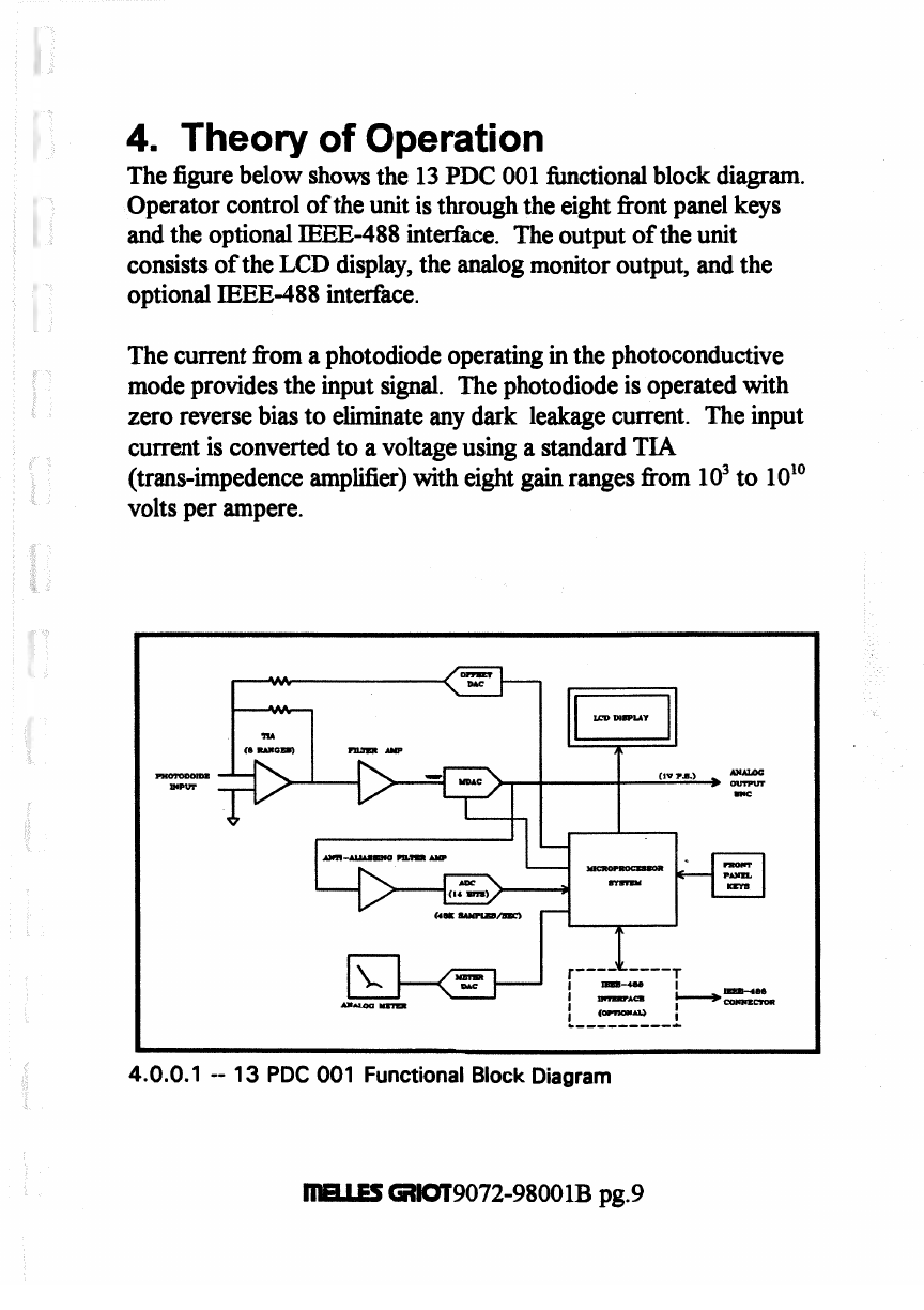
4.
Theory of Operation
The figurebelow showsthe 13
PDC
001functionalblock diagram.
Operator control of the unit isthroughthe eightfiont panel keys
and the optionalIEEE-488 interface. The output of the unit
consistsof the
LCD
display, the analog monitor output, and the
optionalIEEE-488 interface.
Thecurrent &om a photodiode operatingin the photoconductive
mode provides the input signal. Thephotodiode isoperatedwith
zero reverse bias to eliminate any dark leakage current. Theinput
currentis convertedto avoltageusing a standardTIA
(trans-irnpedence amplifier) with eight
gain
ranges fiom
ld
to 10"
voltsper ampere.
4.0.0.1
--
1
3
PDC 001 Functional Block Diagram
maLLS
-9072-98001B pg.9
Thebandwidth of the output is limited by the
TIA
and thefollowing
filteramplifier. Thisfilter amplifieris used to implement the user
optional
30Hz
band limit. The band limited
signal
isthen scaled by
a multiplyingDAC (Digital to Analog Converter) to produce a
1.0
volt
kll
scale
signalat theoutput
BNC
connector.
The output signalis
then
passed through atwo pole,
25
Wk
anti-aliassingfilter amplifierbeforebeing
digitid
by the
ADC
(AnalogtoDigital Converter). TheADC convertsat
48
thousand
samplesper second. The output of the ADC istransferred tothe
microprocessor memory using
DMA (Direct
Memory Access).
Once signal
data
iscollected it isprocessed in blocks of
1024
samples forupdating the analog meter
and
in blocks of
16,384
samplesforupdating theLCD display. Using calibration
informationand operator inputs the microprocessorgeneratesthe
desired displayinformationand drives theLCD and analog meter.
The unit has the capabilityof ofBethg or
nulling
an input signal
which can be equalto the
fbll
scale signal
in
any given range. When
'TKJLL''
is selectedthe unit measuresthe minimum signaland using
a DAC subtractsthe correct amount of current atthe input to zero
that signal. Becausethenulling takes place atthe input of the
TIA
rather
than
in the post processing, no accuracy islost
as
a result.
Thelast functionontheblock diagram isthe optional
IEEE-488.2
interface. The
IEEE
interfaceprovides
all
the hnctionswhich are
availabletotheuser from the fiontpanel plus addition data transfer
modes.
RIBUES
-9072-98001B
pg.
10

5.
Functional Description of
Switches and connectors
5.1
Front
Panel
5.1
.I
MeterZero
Thiskey zerosthe analogmeter to the center of the
%
Deviation
scalewhen in the
%
Deviationmode. Thiskey has no effect on any
offset
NULL
value (section
4.1.2)
appliedtotheinput signal level,
and
has
no effect onthe meterwhen operating the analog meter in
the
"%
Modulation" mode.
5.1.2
NULL
The
NULL
key establishesorremoves an offset value to the input
signal.
When
a null is
set,
the
minimum
input signalvalue is
electronicallysubtractedin hardware hmthe input signal.
Subsequentdisplay readings and the analog output (rear panel
BNC
connector, section 4.2.4) are based on that value
as
a new "zero
reference". This key
will
have an effect on the analog meter in
eitherthe
"%
Modulation" or
"%
Deviation" mode sinceit
establishes(or removes) a zero referencepoint with respect to the
input signal.
5.1.3 Range
The
RANGE
key allows theuser to select autoormanual range
mode. The key is activewhen the
"main"
displayispresent (section
9,
and is not activeunless that screenis displayed. See section
6
forfurtherdiscussion of ranges.
5.1.4
Setup
Pressingthe SETUP key when the "main"display
is
present
will
causethe instrumentto displaya setupmenu,
with
a list of setup
options. Pressing this key &omthe setupmenu (or
any
menu below
the setup menu)
will
alwaysreturn theinstrumentback tothe
"main"
display screen. Instrument setupis discussed beginning with
section
6
of this manual.
maLES
-9072-98001B
pg.
1
1
Table of contents
Popular Measuring Instrument manuals by other brands


International Light Technologies
International Light Technologies ILT2500 Operation manual

HPM
HPM XLP940WEWE instruction manual

sewerin
sewerin FLIS-EX operating instructions

evertz
evertz 5300 instruction manual

Tractel
Tractel dynafor LLX2 Series Operation and maintenance manual

Dräger
Dräger X-zone 5000 Supplement


