7
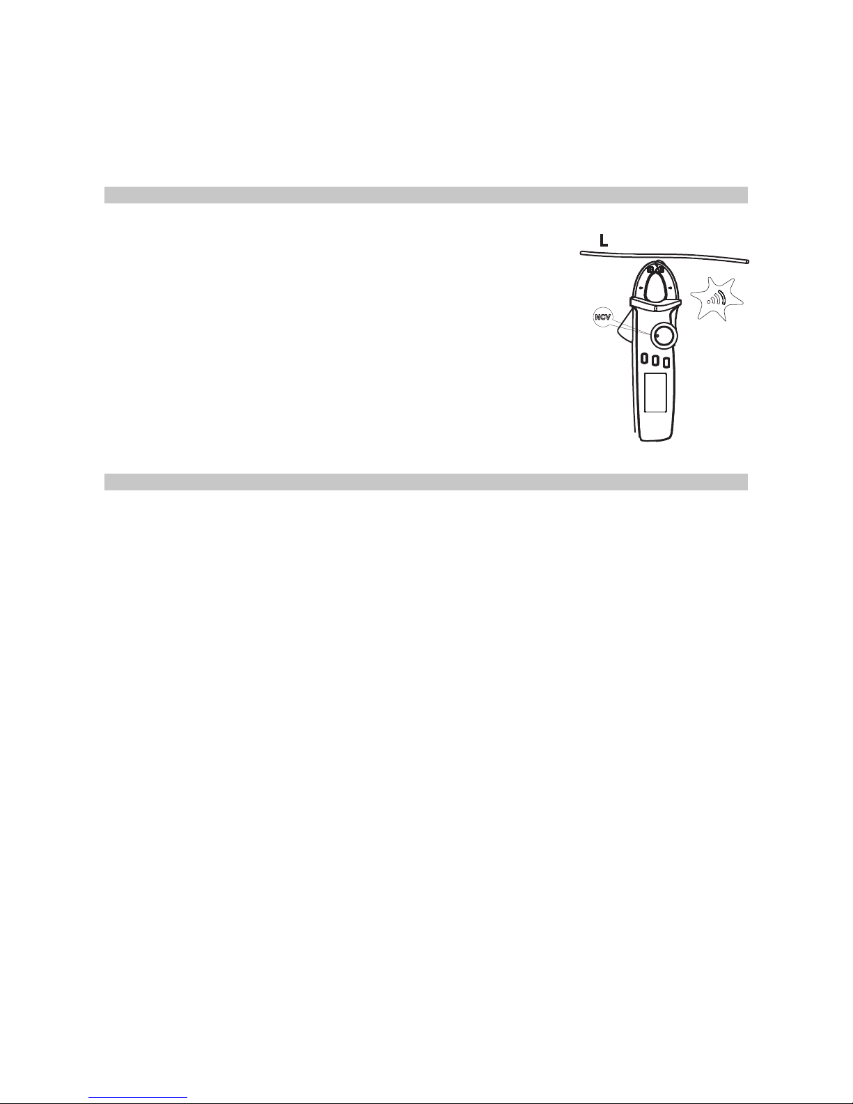
NCV NON-CONTACT ELECTRIC FIELD MEASUREMENT
• If you want to measure whether there is AC voltage/
electromagnetic eld, place the front end of the clamp head
8~15mm close to the test piece.
• When the amplitude of the inductive AC voltage is
approximately ≤ 100V, it displays “EF”.
• If the detected voltage is > 100V, it displays “-” and it has
four “----” levels based on voltage with different buzzing at
each level with NCV light ashing to proportionate to the
eld intensity.
• WARNING: When ranges switch to NCV measurement,
unplug the test plug to avoid electric shock.
OTHER FUNCTIONS
• Press and hold the HOLD button for two seconds to turn on or off the LCD
backlight function.
• Automatic power-off: If the rotary button has not been moved for 15 minutes the
instrument will automatically switch off to save energy. Turn the rotary button to
OFF, then select the required range, or press any button.
•To turn off the automatic power-off function, press and hold the SELECT key, then
turn the instrument on. You will hear five buzzing sounds, which means the
automatic power-off function has been cancelled.
• Turn off and restart the meter, and the automatic power-off function will be re-
enabled.
•The buzzer will send out five warnings one minute before the automatic power-off.
A long buzz will then be heard before turning off. When the automatic power-off
function is cancelled, you will hear five continuous warnings every 15 minutes.
• Buzzer: press any button or rotate the function switch. If such function key is valid,
the buzzer will beep once. When the circuit under test is conductive (<10Ω), the
buzzer will sound continuously.
• When measuring voltage or current out of range, the buzzer will beep to indicate
this.
- When AC or DC voltage is >600V, the buzzer will beep.
- When AC or DC current is >100A, the buzzer will beep.
• Low voltage detection: when the battery voltage is lower than 2.5V, the low battery
symbol appears. Measurement accuracy may be lower once this symbol shows,
so replace the battery as soon as possible. If it is lower than 2.2V, only the low
battery symbol will show after starting up and the instrument will not work.
• When the battery supply voltage lowers to 2.6V, the LCD backlight will be in weak
or non-functional state, but the measurement functions will still work.
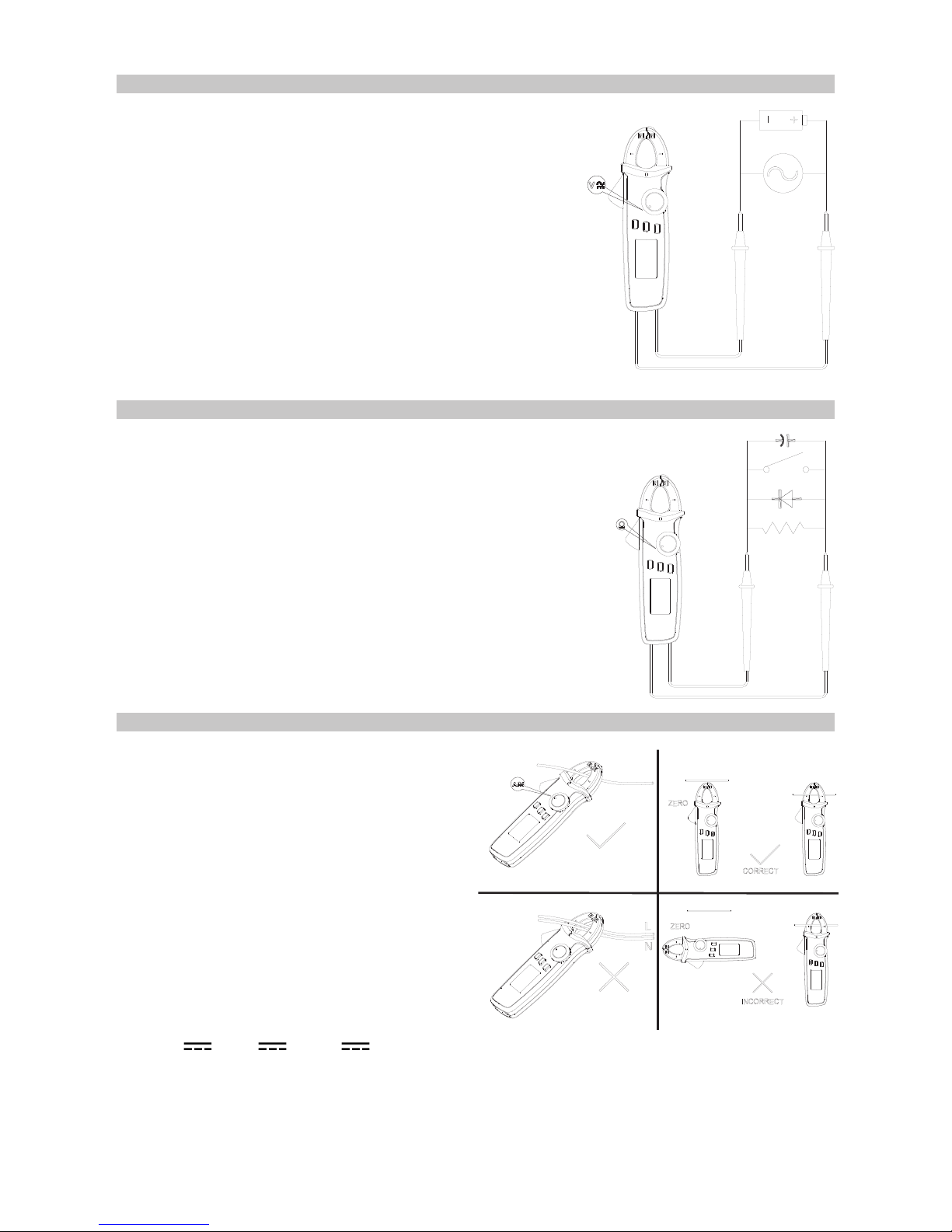
• Open the clamp head, insert the electric wire and close the clamp head.
• Ensure the electric wire is held in the geometric centre, indicated on the clamp
head and make sure the clamp heads are closed.
• Read the measurement data from the LCD. When the reading is positive it means
the current ows from the positive side to the negative side and vice versa.