manuals.online logo
Brands
  1. Home
  2. •
  3. Brands
  4. •
  5. Meltem
  6. •
  7. Gateway
  8. •
  9. Meltem M-WRG-KNX-GW Mounting instructions

Meltem M-WRG-KNX-GW Mounting instructions

VENTILATION & HEAT RECOVERY
INSTALLATION INSTRUCTIONS AND
USER GUIDE
Part no. 744018EN, Week 51/2022 EN
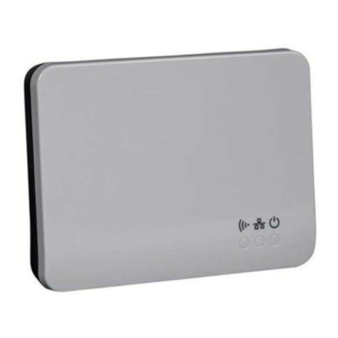
Modbus-KNX gateway
M-WRG-KNX-GW
Fig. 1: Modbus-KNX gateway
1 Introduction
1.1 Notes on these instructions
These instructions contain important information that
should be followed when installing and using the
Modbus-KNX gateway.
►Read all the instructions carefully to avoid possible risks and
mistakes.
►These instructions are part of the product. Keep the instructions
in a safe place for future reference.
NOTICE
►When operating the ventilation unit, also follow the operating
instructions that were supplied with your unit.
1.2 Description
The Modbus-KNX gateway is used to control a ventilation unit of
the operation via Modbus type via KNX bus. It can only be used
in conjunction with an M-WRG-II P/E-M (-F, -FC) or M-WRG-S M
(-F, -FC) unit. The gateway is tted inside the ventilation unit.
The gateway is commissioned using the Engineering Tool Soft-
ware (ETS) in combination with the associated application program.
All functions are parameterised and programmed via the ETS.
NOTICE
— One gateway is needed for each ventilation unit.
— A 24 V auxiliary voltage and a KNX connection are to be
provided by the customer.
1.3 Target group
These installation and operating instructions are aimed at two target
groups:
The activities described in chapter „4 Installation in the M-WRG-II
ventilation unit“, chapter „5 Installation in the M-WRG ventilation
unit“ and chapter „6 Wiring“ must only be carried out by specialised
personnel with the following qualications:
— Training in the installation and commissioning of electrical
devices
— Training in electrical hazards and the local safety requirements
— Knowledge of the relevant standards and directives
— Knowledge and observance of this document and all the safety
instructions
The other chapters of this document are intended for users of the
Modbus-KNX gateway. It assumes prior knowledge of the KNX bus
and the Modbus protocol.
1.4 EU declaration of conformity
The Modbus-KNX gateway described below
Type: M-WRG-KNX-GW
Part number: 5048
manufactured by
Meltem Wärmerückgewinnung GmbH & Co. KG
Am Hartholz 4
82239 Alling
conforms to the regulations and standards listed in the EU Declara-
tion of Conformity.
1.5 Technical data
Product characteristics
Dimensions (W x H x D) 50 mm x 50 mm x 20 mm
Weight approx. 310 g
Housing material Makrolon 6265X V-0 (PC)
Product database contained in the ETS
Ambient conditions
Ambient temperature during operation -20 °C to 55 °C
Ambient temperature for storage and
shipping
-20 °C to 85 °C
IP code IP20
Electrical connection
Bus coupler integrated
Auxiliary voltage for Modbus units 12 V DC
Auxiliary voltage current consumption max. 100 mA
KNX operating voltage (bus voltage) 21 V DC to 32 V DC
KNX power consumption approx. 240 mW at
24 V DC
1.6 Environmentally-friendly disposal
The components of the Modbus-KNX gateway must not be
disposed of in the non-recyclable waste bin.
►In Germany, metal and plastic components should be disposed
of at the local recycling centre. The national regulations in other
EU states should also be followed.
►In Germany, electrical components should be disposed of in
accordance with the Electrical and Electronic Equipment Act
(ElektroG). In other EU states, the national implementation of the
Waste Electrical and Electronic Equipment Directive 2012/19/EU
(WEEE) should be followed.
►The regulations and statutory requirements in your own country
concerning disposal should also be followed.
1.7 Explanation of the symbols used
►This symbol indicates an action to be taken.
— This symbol indicates a list.
2 Safety
The Modbus-KNX gateway is approved only for use in dry interior
areas and must be protected against humidity and moisture to
prevent short-circuits.
2.1 Hazard classication
DANGER
The signal word designates a hazard with a high degree of risk
which, if it is not avoided, will result in death or severe injury.
WARNING
The signal word designates a hazard with a medium degree of
risk which, if it is not avoided, will result in death or severe injury.
CAUTION
The signal word designates a hazard with a low degree of risk
which, if it is not avoided, could result in minor or moderate injury.
NOTICE
A note as used in this manual contains important information
about the product or about a part of the manual to which particular
attention should be paid.
2.2 Intended use
The Modbus-KNX gateway must only be used to control Modbus
units from the M-WRG-II and M-WRG series. Any di󰀨erent or more
extensive usage will be regarded as contrary to the intended use.
The intended use also includes compliance with all the notes in
these instructions.
For any use contrary to the intended use, Meltem Wärmerück-
gewinnung GmbH & Co. KG shall accept no liability for any damage
that may occur and o󰀨ers no warranty that the components will work
perfectly and correctly.
3 Items supplied
— Modbus-KNX gateway M-WRG-KNX-GW
— 4x terminal block (red/black/yellow/white)
— 5-pole terminal (green) with connecting wires
— Velcro strip and network connection cover with cable lead-
through (only when ordering for a M-WRG-Modbus unit)
4 Installation in the M-WRG-II ventilation
unit
4.1 Remove the cover from the ventilation unit
►Using both thumbs, press the two latches on the bottom of the
ventilation unit. The unit cover will come away.
4.2 Remove the electronics compartment cover
DANGER
Potentially fatal voltages in the vicinity of the
connection board
— The electrical installation work must only be carried out by a
qualied electrician.
— The VDE regulations or any special safety regulations appli-
cable in your country apply to the electrical installation work.
►Before starting installation or maintenance work, disconnect
the mains cable for powering the ventilation unit on all poles
from the mains supply.
► Observe the ve safety rules (DIN VDE 0105-100,
EN 50110-1) for working on electrical systems:
— Disconnect from mains (all-pole disconnection of a system
from live parts)
— Secure against reconnection
— Check that the system is voltage-free
— Earth and short-circuit
— Cover or block o󰀨 access to adjacent live parts
1
2
3
Fig. 2: Remove the electronics compartment cover
►Use the screwdriver to loosen the Torx screw (item 1 in Fig. 2)
on the electronics compartment cover (item 2 in Fig. 2).
►Remove the electronics compartment cover to access the
connection board (item 3 in Fig. 2).
4.3 Wire the gateway
►Wire the gateway to the connection board in the ventilation unit
as shown in the wiring diagram (see Fig. 4).
►Wire the gateway to the to the KNX system as shown in the
wiring diagram (see Fig. 5).
4.4 Final tasks
►Position the gateway inside the ventilation unit in the vicinity of
the connection board (item 3 in Fig. 2).
►Secure the electronics compartment cover (item 2 in Fig. 2).
►Attach the cover to the ventilation unit.
5 Installation in the M-WRG ventilation unit
►Using both thumbs, press the two latches on the bottom of the
ventilation unit. The unit cover will come away.
5.1 Replace the network connection cover
1
2
Fig. 3: Replace the network connection cover
►Replace the existing network connection cover with the version
with the cable lead-through (item 1 in Fig. 3, supplied as
standard).
5.2 Wire the gateway
►Wire the gateway to the connection board in the ventilation unit
as shown in the wiring diagram (see Fig. 4).
►Wire the gateway to the to the KNX system as shown in the
wiring diagram (see Fig. 5).
5.3 Final tasks
►Secure the gateway (item 2 in Fig. 3) to the network connection
cover (item 1 in Fig. 3) using the Velcro strip provided.
►Attach the cover to the ventilation unit.
6 Wiring
6.1 Wiring diagram: gateway – connection board in the
ventilation unit
blue
white
red
Fig. 4: Wiring diagram: gateway – connection board
6.2 Wiring diagram: gateway – KNX system
The gateway is connected to an existing KNX system using the KNX
terminal blocks (red/black) provided. An additional 24 V DC power
supply is also required on site (connected via yellow/white terminal
blocks).
The programming button (item 1 in Fig. 5) is on the back of the
gateway.
NOTICE
Note the following when inserting the terminal blocks:
— Connect up the terminal blocks in pairs: tab of the white block
in the groove of the yellow block, tab of the black block in the
groove of the red block.
— The 4-way connections on the terminal blocks point upwards.
yellow
white
red
1
black
21 V DC to 32 V DC 0 V DC KNX+ KNX-
Fig. 5: Wiring diagram: gateway – KNX system
7 Data points
Communication
object
Read/
write
Function/description Unit
1 W Operation
2 R Error message
3 R Frost protection
4 R Exhaust air temperature °C
5 R Outdoor air temperature °C
6 R Extract air temperature °C
7 R Supply air temperature °C
8 R Humidity, extract air %
9 R Humidity, supply air %
10 R CO2, extract air (deactivated by default) ppm
11 R VOC, supply air (deactivated by default) ppm
12 R Ventilation level for extract air m3/h
13 R Ventilation level for supply air m3/h
14 R Filter change
15 R Time until lter change Days
16 R Unit operating hours h
17 R Motor operating hours h
Min. Max. Step Default
18 R/W Rel. humidity threshold value 40 80 1 60 %
19 R/W Min. ventilation level, humidity control 0 100 1/10* 10 m3/h
20 R/W Max. ventilation level, humidity control 10 100 1/10* 60 m3/h
21 R/W CO2starting point 500 1200 1 800/600* ppm
22 R/W Min. ventilation level, CO2control 0 100 1/10* 10 m3/h
23 R/W Max. ventilation level, CO2control 10 100 1/10* 60 m3/h
24 R/W Ventilation level for external control input 10 100 1/10* 60 m3/h
25 R/W Switch-on delay for ext. control input 0 240 1 1 min
26 R/W Run-on time for ext. control input 0 240 1 15 min
27 W Operation unbalanced (extract air motor)
* Value applies to M-WRG
8 Sensors in the di󰀨erent ventilation unit types
Ventilation unit type
Sensor type
M-WRG-II P-M /
M-WRG-II E-M
M-WRG-II P-M-F /
M-WRG-II E-M-F
M-WRG-II P-M-FC /
M-WRG-II E-M-FC
with option
M-WRG-II O/VOC-AUL
M-WRG-S M M-WRG-S M-F M-WRG-S M-FC –
Exhaust air temperature X X X X
Outdoor air temperature X X X
Extract air temperature X X X
Supply air temperature X X X
Rel. humidity, extract air X X X
Rel. humidity, supply air X X X
CO2, extract air X X
VOC, supply air X
9 Conguration
The KNX gateway M-WRG-KNX-GW is congured via the ETS.
The associated application program can be obtained from the ETS
catalogue.
The gateway is supplied unprogrammed. All functions are set and
programmed via the ETS.
The gateway is congured with the following settings at the factory:
Fig. 6: Factory settings for the KNX gateway
10 Read communication objects
The channels of the gateway are predened with the possible data
points. Communication objects which are read only can be linked
directly to a group address and displayed.
11 Write communication objects
Settings can be changed on the unit using communication objects
17-25. To do this, the value for the communication object is changed
accordingly.
Fig. 7: Communication objects
12 Ventilation levels setting
Use the following table for communication objects 0 and 26 in order
to change the ventilation level (VL) of the unit:
Communication object 0
Value Mode
0 OFF OFF
1 - 99 Volume ow rate VL %
SUP / ETA
100 -
200*
Supply air volume
unbalanced
VL % SUP Only in conjunction with
communication object 26
202 Automatic mode SUP / ETA
203 Humidity mode SUP / ETA
204 CO2mode SUP / ETA
205
Intensive ventilation
SUP / ETA
Communication object 26
Value Mode
100 -
200*
Extract air volume
unbalanced
VL % ETA Only in conjunction with
communication object 0,
value 100-200
* Value corresponds to m3/h minus 100 (example: 130 = 30 m3/h)
13 Typical application
Fig. 8: Typical application

This manual suits for next models

1

Other Meltem Gateway manuals

Meltem M-WRG-GW Mounting instructions

Meltem

Meltem M-WRG-GW Mounting instructions

Popular Gateway manuals by other brands

MSA fieldserver EZ Series operating manual

MSA

MSA fieldserver EZ Series operating manual

Control Data Systems Versa Router 950 user manual

Control Data Systems

Control Data Systems Versa Router 950 user manual

Edge-Core CSR300/AS7315-30X quick start guide

Edge-Core

Edge-Core CSR300/AS7315-30X quick start guide

RTA 460BC-NNA4 Product user guide

RTA

RTA 460BC-NNA4 Product user guide

Dension Gateway Lite user manual

Dension

Dension Gateway Lite user manual

Nokia 100i - IP VPN - Gateway installation guide

Nokia

Nokia 100i - IP VPN - Gateway installation guide

Citrix NetScaler MPX manual

Citrix

Citrix NetScaler MPX manual

Gallagher WiFi GATEWAY installation instructions

Gallagher

Gallagher WiFi GATEWAY installation instructions

Cypress CTM-200 R2 manual

Cypress

Cypress CTM-200 R2 manual

Vibicom VB-101 Installation and operation manual

Vibicom

Vibicom VB-101 Installation and operation manual

turck BL20 user manual

turck

turck BL20 user manual

Matrix Telecom SARVAM UMG quick start

Matrix Telecom

Matrix Telecom SARVAM UMG quick start

Dialogic 2000 Series Getting started guide

Dialogic

Dialogic 2000 Series Getting started guide

Caimore CM510-x-50P Series Operation manual

Caimore

Caimore CM510-x-50P Series Operation manual

ACT'L eWON4002 installation guide

ACT'L

ACT'L eWON4002 installation guide

Juniper SRX340 Hardware guide

Juniper

Juniper SRX340 Hardware guide

KKM KGateway Configuration manual

KKM

KKM KGateway Configuration manual

Nortel MCG3100 installation guide

Nortel

Nortel MCG3100 installation guide

manuals.online logo
manuals.online logoBrands
  • About & Mission
  • Contact us
  • Privacy Policy
  • Terms and Conditions

Copyright 2025 Manuals.Online. All Rights Reserved.