Meltem M-WRG-FBH User manual

Meltem Wärmerückgewinnung GmbH & Co. KG
Am Hartholz 4 · D-82239 Alling
VENTILATION THE RIGHT WAY
VENTILATION & HEAT RECOVERY
USER GUIDE
HOME VENTILATION WITH HEAT RECOVERY
Wireless remote control
M-WRG-FBH
Part no. 5302-25-01 Week 04/2017 EN

User guide
Wireless remote control M-WRG-FBH
- 2 -
Meltem Wärmerückgewinnung GmbH & Co. KG
Am Hartholz 4 · D-82239 Alling
VENTILATION THE RIGHT WAY
VENTILATION & HEAT RECOVERY
Contents
1 Introduction ..................................................................................................................... 5
1.1 Notes on the user guide ................................................................................................... 5
1.2 Description ........................................................................................................................ 5
1.3 Target group ..................................................................................................................... 6
1.4 EC Declaration of Conformity ........................................................................................... 6
1.5 Nameplate ........................................................................................................................ 6
1.6 Technical data ................................................................................................................... 6
1.6.1 Electrical data ................................................................................................................... 6
1.6.2 Dimensions and weight .................................................................................................... 6
1.6.3 Ambient conditions ........................................................................................................... 6
1.7 Storage ............................................................................................................................. 6
1.8 Environmentally-friendly disposal ..................................................................................... 7
1.9 Revision index .................................................................................................................. 7
1.10 Explanation of the symbols used ...................................................................................... 7
2 Safety instructions ......................................................................................................... 8
2.1 Hazardclassication ......................................................................................................... 8
2.2 Notes on using the ventilation units safely ....................................................................... 8
2.3 Notes on the batteries ...................................................................................................... 8
2.4 Notes on using ventilation units with the wireless remote control .................................... 8
2.5 Intended use ..................................................................................................................... 9
3 Warranty and liability ..................................................................................................... 9
3.1 Warranty ........................................................................................................................... 9
3.2 Liability .............................................................................................................................. 9
4 Items supplied ................................................................................................................ 9
5 Controls and displays .................................................................................................. 10
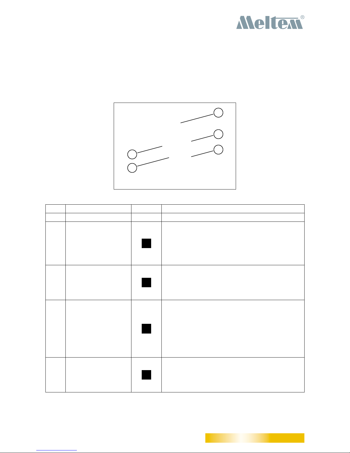
5.1 Buttons and LCD display ................................................................................................ 10
5.2 Symbols on the LCD display ........................................................................................... 11
6 Starting up ..................................................................................................................... 13
6.1 Insert batteries in wireless remote control ...................................................................... 13
6.2 Establish connection between wireless remote control and ventilation unit ................... 14
6.3 Disconnect connection between wireless remote control and ventilation unit ................ 16
7 Display modes .............................................................................................................. 18
7.1 Idle mode ........................................................................................................................ 18
7.2 Default view .................................................................................................................... 18
7.3 Congureactiveventilationprogram .............................................................................. 18
7.4 Ventilation programs ....................................................................................................... 18
7.5 Device settings ............................................................................................................... 19
7.6 Manual mode .................................................................................................................. 19
7.7 Connection mode ........................................................................................................... 19
8 Overview of the ventilation programs ........................................................................ 20
8.1 “Supply air operation (Summer mode)” program ............................................................ 20
8.2 “Extract air operation” program ....................................................................................... 20
8.3 “Humidity control” program ............................................................................................. 21

User guide
Wireless remote control M-WRG-FBH
- 3 -
Meltem Wärmerückgewinnung GmbH & Co. KG
Am Hartholz 4 · D-82239 Alling
VENTILATION THE RIGHT WAY
VENTILATION & HEAT RECOVERY
8.4 “Mixed gas/CO2control” program ................................................................................... 21
8.5 “Automatic mode” program ............................................................................................. 22
8.6 “Continuous operation” program ..................................................................................... 22
8.7 “Intensive ventilation (15 min)” program ......................................................................... 22
8.8 Device settings ............................................................................................................... 22
9 Operating the ventilation unit with the wireless remote control M-WRG-FBH ....... 23
9.1 Select ventilation program .............................................................................................. 23
9.1.1 Graphical illustration of the steps to select a ventilation program .................................. 23
9.2 Temporarily set ventilation levels in manual mode ......................................................... 24
9.2.1 Activate manual mode .................................................................................................... 24
9.2.2 Deactivate manual mode ................................................................................................ 25
9.3 Congureactiveventilationprogramandpermanentlysavesettings ............................ 26
9.3.1 Congureandsaveparametersforactiveventilationprogram ...................................... 26
9.3.2 Graphicalillustrationofthestepstoconguretheactiveventilationprogram ................ 26
9.3.3 Overview of the variable parameters in the active ventilation program .......................... 27
9.4 Conguredevicesettings ............................................................................................... 28
9.4.1 CongureandsaveparametersinDevicesettingsmenu .............................................. 28
9.4.2 Graphical illustration of the steps in the Device settings menu ...................................... 29
9.4.3 Overview of the variable parameters in the Device settings menu ................................. 30
10 Special functions .......................................................................................................... 32
10.1 Standby mode ................................................................................................................ 32
10.1.1 Set ventilation unit to Standby mode .............................................................................. 32
10.1.2 Exit standby mode .......................................................................................................... 32
10.2 Activate or deactivate intensive ventilation ..................................................................... 32
10.3 Resetlterchangeindicator ........................................................................................... 32
11 Operation with multiple ventilation units ................................................................... 33
12 Troubleshooting ........................................................................................................... 34

User guide
Wireless remote control M-WRG-FBH
- 4 -
Meltem Wärmerückgewinnung GmbH & Co. KG
Am Hartholz 4 · D-82239 Alling
VENTILATION THE RIGHT WAY
VENTILATION & HEAT RECOVERY

User guide
Wireless remote control M-WRG-FBH
- 5 -
Meltem Wärmerückgewinnung GmbH & Co. KG
Am Hartholz 4 · D-82239 Alling
VENTILATION THE RIGHT WAY
VENTILATION & HEAT RECOVERY
1 Introduction
1.1 Notes on the user guide
This user guide contains important information that should be followed when using the
M-WRG-FBH wireless remote control.
►Read all the instructions carefully to avoid possible risks and mistakes.
►These instructions are part of the product. Keep the instructions in a safe place for future
reference.
NOTE
►When operating the ventilation unit, also follow the operating instructions that were sup-
plied with your unit.
1.2 Description
This user guide describes how to set up and operate the M-WRG-S/Z-T(-F,-FC) decentralised
ventilation units (see Fig. 1) with the M-WRG-FBH wireless remote control (see Fig. 2).
The M-WRG-FBH wireless remote control has four buttons and an LCD display that provides
information on the ventilation unit’s current operating status. Up to six ventilation units of the same
type can be controlled with one wireless remote control. The wireless remote control can be used
to carry out the following actions:
— Establish and disconnect the connection between wireless remote control and ventilation
unit
— Activate the ventilation unit or set it to Standby mode
— Select ventilation program
— Conguretheventilationprogram
— Setdevice-specicparameters
Fig. 1: M-WRG-S/Z-T(-F,-FC) ventilation unit Fig. 2: M-WRG-FBH wireless remote control

User guide
Wireless remote control M-WRG-FBH
- 6 -
Meltem Wärmerückgewinnung GmbH & Co. KG
Am Hartholz 4 · D-82239 Alling
VENTILATION THE RIGHT WAY
VENTILATION & HEAT RECOVERY
1.3 Target group
This user guide is intended for users of the M-WRG-FBH wireless remote control. No special prior
knowledge is needed.
1.4 EC Declaration of Conformity
The wireless remote control described below
Type: Part number
M-WRG-FBH 5478-10
manufactured by
Meltem Wärmerückgewinnung GmbH & Co. KG
Am Hartholz 4
82239 Alling
conforms to the regulations and standards listed in the EC Declaration of Conformity provided.
1.5 Nameplate
Youwillndthenameplateontheinsideofthebatterycompartmentcover(seeitem1inFig.5on
page 13).
1.6 Technical data
1.6.1 Electrical data
Power supply Two 1.5 V alkaline batteries, size AA
Communication frequency 868.3 MHz
Transmitter output power Min. 0 dBm
IP rating to IEC 60529 IP20
1.6.2 Dimensions and weight
Unit dimensions 62.2 mm x 112.2 mm x 30 mm (W x H x D)
Weight without batteries Approx. 77 g
Weight with two 1.5 V alkaline batteries Approx. 123 g
1.6.3 Ambient conditions
Ambient temperature during operation 0 °C to +40 °C
Ambient temperature for shipping and storage -20 °C to +50 °C
Relative humidity (non-condensing) 5 % to 90 %
1.7 Storage
►Store the wireless remote control in its original packaging in a dry place where the temper-
ature ranges between -20 °C and +50 °C.

User guide
Wireless remote control M-WRG-FBH
- 7 -
Meltem Wärmerückgewinnung GmbH & Co. KG
Am Hartholz 4 · D-82239 Alling
VENTILATION THE RIGHT WAY
VENTILATION & HEAT RECOVERY
1.8 Environmentally-friendly disposal
The components of the wireless remote control must not be disposed of in the residual waste bin.
►In Germany, metal and plastic components should be disposed of at the local recy-
cling centre. The national regulations in other EU states should also be followed.
►In Germany, electrical components should be disposed of in accordance with the
Electrical and Electronic Equipment Act (ElektroG). In other EU states, the na-
tional implementation of the Waste Electrical and Electronic Equipment Directive
2012/19/EC (WEEE) should be followed.
►In Germany, rechargeable batteries and accumulators should be disposed of in ac-
cordance with the Batteries Act (BattG). The national implementation of the Battery
Directive 2006/66/EC should be followed in other EU states.
►The regulations and statutory requirements in your own country concerning disposal
should also be followed.
1.9 Revision index
Edition Manual Date
1st edition User guide for wireless remote control M-WRG-FBH Week 04/2017 EN
1.10 Explanation of the symbols used
►This symbol indicates an action to be taken.
— This symbol indicates a list.

User guide
Wireless remote control M-WRG-FBH
- 8 -
Meltem Wärmerückgewinnung GmbH & Co. KG
Am Hartholz 4 · D-82239 Alling
VENTILATION THE RIGHT WAY
VENTILATION & HEAT RECOVERY
2 Safety instructions
These instructions contain notes that you must follow for your own personal safety and to avoid
injury and damage to property. They are highlighted by warning triangles and are shown as follows
according to the level of danger.
2.1 Hazard classication
DANGER
The signal word designates a hazard with a high degree of risk which, if it is not avoided, will result
in death or severe injury.
WARNING
The signal word designates a hazard with a medium degree of risk which, if it is not avoided, will
result in death or severe injury.
CAUTION
The signal word designates a hazard with a low degree of risk which, if it is not avoided, could
result in minor or moderate injury.
NOTE
A note as used in this manual contains important information about the product or about a part of
the manual to which particular attention should be paid.
2.2 Notes on using the ventilation units safely
CAUTION
Starting and using the ventilation unit
►Do not start up the ventilation unit until it is fully installed.
►Always make sure that the cover is closed and locked in place before using the ventilation
unit.
2.3 Notes on the batteries
CAUTION
Risk of explosion if batteries are exposed to high temperatures
►Protect the batteries against high temperatures due to direct sunlight, for example.
► Neverthrowbatteriesintore.
2.4 Notes on using ventilation units with the wireless remote control
— This wireless remote control may be used by children from 8 years old and by persons of
restricted physical, sensory or mental abilities or persons lacking experience and knowl-
edge if they are supervised or have been instructed in how to use the unit safely and un-
derstand the associated hazards. Do not allow children to play with the unit. Cleaning and

User guide
Wireless remote control M-WRG-FBH
- 9 -
Meltem Wärmerückgewinnung GmbH & Co. KG
Am Hartholz 4 · D-82239 Alling
VENTILATION THE RIGHT WAY
VENTILATION & HEAT RECOVERY
user maintenance must not be carried out by children unless they are supervised.
►Follow the regulations applicable in your country concerning the age from which peo-
ple may be permitted to operate the wireless remote control.
2.5 Intended use
— Thewirelessremotecontrolmustonlybeusedtocontrolandsetthedevice-specicfunc-
tions of the M-WRG-S/Z-T(-F, -FC) ventilation units. Any different or more extensive usage
will be regarded as contrary to the intended use.
— The intended use also includes compliance with all the notes in the user guide.
— Theventilationunitmustnotbeoperatedwithoutairlters.
— For any use contrary to the intended use, Meltem Wärmerückgewinnung GmbH & Co.
KG shall accept no liability for any damage that may occur and offers no warranty that the
components will work perfectly and correctly.
3 Warranty and liability
3.1 Warranty
The warranty will be invalidated if:
— The inner cover (see item 2 in Fig. 6 on page 13) with the battery compartment was
removed.
— Repairs were not carried out by Meltem or by an authorised specialist company.
— The warranty does not cover wearing parts such as batteries.
3.2 Liability
The manufacturer’s liability shall not apply in the following cases:
— The inner cover (see item 2 in Fig. 6 on page 13) with the battery compartment was
removed.
— Repairs were not carried out by Meltem or by an authorised specialist company.
4 Items supplied
The M-WRG-FBH wireless remote control is supplied with the following items:
Item Designation Quantity
1 M-WRG-FBH wireless remote control 1x
2 1.5 V alkaline battery, size AA 2x
3 User guide for wireless remote control M-WRG-FBH 1x
Table 1: Items supplied with the M-WRG-FBH wireless remote control

User guide
Wireless remote control M-WRG-FBH
- 10 -
Meltem Wärmerückgewinnung GmbH & Co. KG
Am Hartholz 4 · D-82239 Alling
VENTILATION THE RIGHT WAY
VENTILATION & HEAT RECOVERY
5 Controls and displays
5.1 Buttons and LCD display
The M-WRG-FBH wireless remote control has four buttons and an LCD display that provides infor-
mation on the operating status. The buttons perform multiple functions.
1
2
3
4
5
Fig. 3: Controls and displays
Item Element Symbol Function
1 LCD display - Displays the current menu
2 “Up” button — Increase value
— Select next menu option
— Activate LCD display
— Leave manual mode
— Activate / deactivate intensive ventilation
3 “On” button — Call up menu with ventilation programs
— Activate LCD display
— Activate / deactivate Standby mode
— Return to previous menu
4 “Menu” button — CallupCongurationmenuforactiveventilation
program
— CallupnextitemfromtheCongurationmenu
— Activate LCD display
— Connect or disconnect remote control from venti-
lation unit
— Resetlterchangeindicator
5 “Down” button — Reduce value
— Select previous menu item
— Activate LCD display
— Leave manual mode
Table 2: Buttons and LCD display

User guide
Wireless remote control M-WRG-FBH
- 11 -
Meltem Wärmerückgewinnung GmbH & Co. KG
Am Hartholz 4 · D-82239 Alling
VENTILATION THE RIGHT WAY
VENTILATION & HEAT RECOVERY
5.2 Symbols on the LCD display
Fig. 4: Symbols on the LCD display
Symbol Name Description
Ventilation units One dot is displayed for every ventilation unit that is connect-
ed(upto6).Theashingdotcorrespondstotheventilation
unit with which communication is currently active.
Error — Thesymbolisdisplayedcontinuouslyiftheairlteris
dirty (see section 12 on page 34).
— Thesymbolashesiftheone-yearlterchangeintervalis
exceeded (see section 12 on page 34).
Frost protection The symbol appears when the frost protection function is
active.
Exclamation mark The symbol appears when the ventilation unit signals an
error (see section 12 on page 34).
RF communication The symbol appears when the remote control is connected
to a ventilation unit and when communication is in progress
with that ventilation unit.
Battery The symbol appears when the batteries in the wireless
remotecontrolarealmostatandneedtobechanged(see
section 6.1 on page 13).
Supply air Symbol for the “Supply air operation (Summer mode)” venti-
lation program. Flashes when activated.
Min/Max The symbol indicates whether a value is a minimum or max-
imum.
Extract air Symbol for the “Extract air operation” ventilation program.
Flashes when activated.

User guide
Wireless remote control M-WRG-FBH
- 12 -
Meltem Wärmerückgewinnung GmbH & Co. KG
Am Hartholz 4 · D-82239 Alling
VENTILATION THE RIGHT WAY
VENTILATION & HEAT RECOVERY
Symbol Name Description
Relative humidity (RH) — Symbol for the “Humidity control” ventilation program.
Flashes when activated.
— The symbol and value for the relative humidity appear
continuously in every ventilation program if the ventilation
unit is equipped with a humidity sensor.
Percent The symbol and two-digit value for the relative humidity ap-
pear continuously in every ventilation program if the ventila-
tion unit is equipped with a humidity sensor.
Manual mode The symbol appears when the user manually changes the
value calculated or set for the ventilation level. The changes
are not stored permanently.
Continuous operation Symbol for the “Continuous operation” ventilation program.
Flashes when activated.
Mixed gas/CO2— Symbol for the “Mixed gas/CO2control” ventilation pro-
gram. Flashes when activated.
— The symbol and value for the mixed gas/CO2concen-
tration appear continuously in every ventilation program
if the ventilation unit is equipped with a mixed gas/CO2
sensor.
ppm The symbol and four-digit value for the mixed gas/CO2con-
centration appear continuously in every ventilation program if
the ventilation unit is equipped with a mixed gas/CO2sensor.
Intensive ventilation Symbol for the “Intensive ventilation” program. Flashes when
activated.
Automatic mode Symbol for the “Automatic mode” ventilation program. Flash-
es when activated.
Gateway The symbol appears when the ventilation unit is controlled
via a gateway or there is an active ventilation program that is
not supported by the wireless remote control.
Device settings Symbol for the Device settings menu. This is used to read,
congureandpermanentlystoredevice-specicsettings.
Table 3: Symbols on the LCD display

User guide
Wireless remote control M-WRG-FBH
- 13 -
Meltem Wärmerückgewinnung GmbH & Co. KG
Am Hartholz 4 · D-82239 Alling
VENTILATION THE RIGHT WAY
VENTILATION & HEAT RECOVERY
6 Starting up
6.1 Insert batteries in wireless remote control
►Remove the cover (item 1 in Fig. 5) from the battery compartment on the back of the wire-
less remote control. To do this, pull the cover down as far as it will go, then lift off.
►Insert the batteries supplied in the battery compartment.
NOTE
Make sure that the polarity symbols on the batteries match the polarity symbols in the
battery compartment. The wireless remote control may be damaged if the batteries are
wrongly inserted.
The wireless remote control initialises when the batteries are inserted. The following infor-
mation appears on the LCD display:
— First all available symbols are displayed (see Fig. 4 on page 11).
— Then the wireless remote control’s software version is displayed, e.g. “r001”.
— This is followed by the default view (see section 7.2 on page 18).
►Attach the cover to close the battery compartment.
Fig. 5: Remove battery compartment cover
1
Fig. 6: Insert batteries in battery compartment
1
2

User guide
Wireless remote control M-WRG-FBH
- 14 -
Meltem Wärmerückgewinnung GmbH & Co. KG
Am Hartholz 4 · D-82239 Alling
VENTILATION THE RIGHT WAY
VENTILATION & HEAT RECOVERY
6.2 Establish connection between wireless remote control and ventilation unit
►Switch the ventilation unit on.
NOTE
When the ventilation unit is switched on, it remains in connection mode for 5 minutes. The
connection between wireless remote control and ventilation unit can only be established
during this period.
►Press any button on the wireless remote control to activate the LCD display on the wire-
less remote control and switch to the default view (see section 7.2 on page 18). If there
is no ventilation unit yet connected, the LCD display contains the following information:
Fig. 7: Default view (no ventilation unit connected)
►Hold down button and at the same time for more than 3 seconds to call up the
menu for connecting/disconnecting a ventilation unit.
— If there is no ventilation unit yet connected, the LCD display contains the following
information:
Fig. 8: Connection menu (no ventilation unit connected)
— If there are already ventilation units connected, the LCD display shows the number of
connected ventilation units both as a number and in the form of dots (4 in this example):
Fig. 9: Connection menu (4 ventilation units already connected)
►Hold down the button for more than 3 seconds to connect a new ventilation unit.
The LCD display shows the following information:
Fig. 10: Connect new ventilation unit
Thedotinthetopleftcornerashestoindicatethatventilationunit1canbeconnected.

User guide
Wireless remote control M-WRG-FBH
- 15 -
Meltem Wärmerückgewinnung GmbH & Co. KG
Am Hartholz 4 · D-82239 Alling
VENTILATION THE RIGHT WAY
VENTILATION & HEAT RECOVERY
►Press the button to establish the connection between wireless remote control and
ventilation unit.
While the connection to the ventilation unit is initialising, the ventilation unit beeps and the
LCD display on the wireless remote control shows the following information:
Fig. 11: Initialise connection set-up
The dot representing the ventilation unit and the symbolash.
— Once the connection has been established successfully, the LCD display shows the
following information:
Fig. 12: Connection successfully established
The dot representing the ventilation unit and the symbolash.
— If no connection could be established, the LCD display shows the following informa-
tion:
Fig. 13: Connection not successfully established
Thedotrepresentingtheventilationunitashes.The and symbols are dis-
played.
When the or button is pressed or after 3 seconds, the Connection menu appears
(see Fig. 8 on page 14).

User guide
Wireless remote control M-WRG-FBH
- 16 -
Meltem Wärmerückgewinnung GmbH & Co. KG
Am Hartholz 4 · D-82239 Alling
VENTILATION THE RIGHT WAY
VENTILATION & HEAT RECOVERY
6.3 Disconnect connection between wireless remote control and ventilation unit
►Switch the ventilation unit on.
NOTE
When the ventilation unit is switched on, it remains in connection mode for 5 minutes. The
connection between wireless remote control and ventilation unit can only be disconnected
during this period.
►Press any button on the wireless remote control to activate the LCD display on the wire-
less remote control and switch to the default view (see section 7.2 on page 18).
►Hold down button and at the same time for more than 3 seconds to call up the
menu for connecting/disconnecting a ventilation unit.
The LCD display shows the number of connected ventilation units both as a number and in
the form of dots (2 in this example):
Fig. 14: Connection menu (2 ventilation units already connected)
►Hold down the button for more than 3 seconds to disconnect a connection between
wireless remote control and ventilation unit.
The LCD display shows the following information:
Fig. 15: Disconnect connection to ventilation unit
The number of the currently selected ventilation unit is displayed and the corresponding
dotashes.
►Use the or button to select the ventilation unit for which you want to disconnect the
connection.
NOTE
Hold down the button for more than 3 seconds to activate the buzzer on the currently
selected ventilation unit. This will allow you to check that you have selected the right venti-
lation unit and that it is within range.

User guide
Wireless remote control M-WRG-FBH
- 17 -
Meltem Wärmerückgewinnung GmbH & Co. KG
Am Hartholz 4 · D-82239 Alling
VENTILATION THE RIGHT WAY
VENTILATION & HEAT RECOVERY
►Press the button to disconnect the connection between wireless remote control and
ventilation unit.
While the connection to the ventilation unit is initialising, the ventilation unit beeps and the
LCD display on the wireless remote control shows the following information:
Fig. 16: Initialise connection set-up
The dot representing the ventilation unit and the symbolash.
— Once the connection has been successfully disconnected, the LCD display shows the
following information:
Fig. 17: Connection successfully disconnected
The dot representing the ventilation unit and the symbolash.
— If no connection could be established, the LCD display shows the following informa-
tion:
Fig. 18: Connection not successfully disconnected
Thedotrepresentingtheventilationunitashes.The and symbols are dis-
played.
When the or button is pressed or after 3 seconds, the Connection menu appears
(see Fig. 14 on page 16).

User guide
Wireless remote control M-WRG-FBH
- 18 -
Meltem Wärmerückgewinnung GmbH & Co. KG
Am Hartholz 4 · D-82239 Alling
VENTILATION THE RIGHT WAY
VENTILATION & HEAT RECOVERY
7 Display modes
7.1 Idle mode
The LCD display switches off after 20 seconds
inactivity. Press any button to switch the wireless
remote control from idle mode to the default view.
7.2 Default view
The default view displays the currently selected
ventilation program. The wireless remote control
also checks the operating parameters (e.g. ven-
tilation level for supply air and extract air, relative
humidity, etc.) and shows them on the LCD dis-
play (see Table 3 on page 12 for an explanation
of the symbols). Which operating parameters are
displayed depends on the currently selected ven-
tilation program and the ventilation unit features
(humidity sensor, mixed gas/CO2sensor). The dot
representing the selected ventilation unit and the
symbolfortheactiveventilationprogramash.
7.3 Congure active ventilation program
Press the button in the default view to open
themenuforconguringtheactiveventilationpro-
gram.Hereyoucanread,congureandperma-
nently store the most important parameters (ven-
tilation levels, thresholds) for the active ventilation
program (see section 9.3 on page 26).
7.4 Ventilation programs
Press the button in the default view to open
the menu for selecting the ventilation programs.
Which ventilation programs are displayed depends
on the ventilation unit features (humidity sensor,
mixed gas/CO2sensor, there is an explanation of
the symbols used in Table 3 from page 11). The
symbolfortheactiveventilationprogramashes.
Fig. 19: Display mode – Idle mode
Fig. 20: Display mode – Default view
Fig. 21: Displaymode–Congureactiveventilation
program
Fig. 22: Display mode – Ventilation programs

User guide
Wireless remote control M-WRG-FBH
- 19 -
Meltem Wärmerückgewinnung GmbH & Co. KG
Am Hartholz 4 · D-82239 Alling
VENTILATION THE RIGHT WAY
VENTILATION & HEAT RECOVERY
7.5 Device settings
Select the symbol in the ventilation pro-
grams display mode to open the Device settings
menu.Hereyoucanread,congureandperma-
nently store the ventilation program parameters
anddevice-specicsettings(seesection9.4on
page 28).
7.6 Manual mode
Press the or button in the default view
to temporarily increase or reduce the ventilation
level. The ventilation level of the extract air, sup-
ply air or both is changed according to the active
ventilation program.
The symbol signals that manual mode is active
(see section 9.2 on page 24).
7.7 Connection mode
Hold down the and buttons at the same
time in the default view and for longer than 3 sec-
onds to open the Connection mode display (see
also section 6.2 on page 14).
Fig. 23: Display mode – Device settings
Fig. 24: Display mode – Manual mode
Fig. 25: Display mode – Connection mode

User guide
Wireless remote control M-WRG-FBH
- 20 -
Meltem Wärmerückgewinnung GmbH & Co. KG
Am Hartholz 4 · D-82239 Alling
VENTILATION THE RIGHT WAY
VENTILATION & HEAT RECOVERY
8 Overview of the ventilation programs
There are different ventilation programs available for selection, depending on the type of ventilation
unit. The ventilation unit informs the wireless remote control which ventilation programs it supports.
Theindividualventilationprogramsareidentiedbysymbols(seesection7.4onpage18)on
the LCD display. The symbol for the active ventilation program and the dot representing the select-
edventilationunitash.Thedescriptionoftheindividualventilationprogramsrelatestothefactory
default settings.
8.1 “Supply air operation (Summer mode)” program
Symbol Default view Description
The ventilation unit runs in supply air operation with limited
heat recovery. This operating mode allows the cooler outdoor
air to be routed into the building on summer nights, for exam-
ple.
NOTE
This ventilation program must not be used in sub-zero temper-
atures otherwise the ventilation unit will constantly activate the
frost protection function or switch off altogether.
8.2 “Extract air operation” program
Symbol Default view Description
The ventilation unit runs in extract air operation with limited
heat recovery. This operating mode can be selected to route
used air to the outside. If there are two ventilation units pres-
ent, cross-ventilation can be achieved in the building by setting
one ventilation unit to supply air operation and the other to
extract air operation.
NOTE
Cross-ventilation must not be used in sub-zero temperatures
otherwise the ventilation unit that is set to supply air operation
will constantly activate the frost protection or switch off alto-
gether.
Other manuals for M-WRG-FBH
1
Table of contents
Other Meltem Remote Control manuals
Popular Remote Control manuals by other brands

Satel
Satel RK-1K installation guide

LG
LG Magic Remote Quick setup guide

Dual Inventive
Dual Inventive ZKL 3000 RC Manual for Switching

SMK-Link
SMK-Link Global Presenter VP4350 user manual

Mitsubishi Electric
Mitsubishi Electric PAC-YT53CRAU installation manual

Siemens
Siemens 5WG1 255-7AB01 Operating and mounting instructions