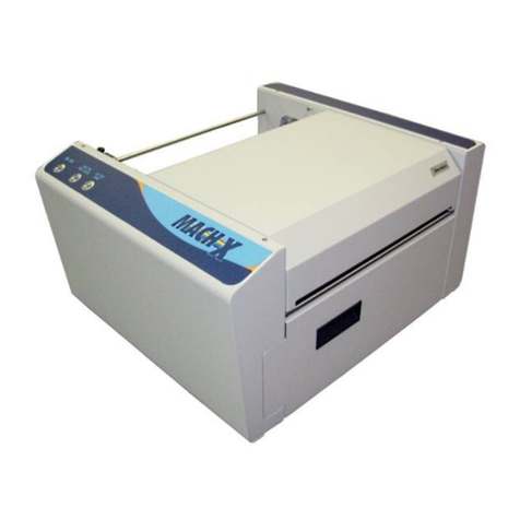
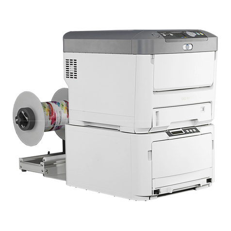
Memjet MACH X Manual

MACH X
DIGITAL COLOR
LABEL PRINTER
OPERATOR’s GUIDE
Rev 07-30-13
Premliminary

SAFETY PRECAUTIONS
THIS EQUIPMENT PRESENTS NO PROBLEM WHEN USED PROPERLY.
HOWEVER, CERTAIN SAFETY RULES SHOULD BE OBSERVED WHEN
OPERATING THE MACH X LABEL PRINTER.
BEFORE USING THE PRINTER, YOU SHOULD READ THIS MANUAL
CAREFULLY AND FOLLOW THE RECOMMENDED PROCEDURES, SAFETY
WARNINGS, AND INSTRUCTIONS:
Keep hands, hair, and clothing clear of rollers and other moving parts.
Avoid touching moving parts or materials while the machine is in use. Before clearing a jam, be
sure machine mechanisms come to a stop.
Always turn off the machine before making adjustments, cleaning the machine, or performing
any maintenance covered in this manual.
The power cord and power supply supplied with the machine should be plugged into a properly
grounded, easily accessible wall outlet located near the machine. Failure to properly ground the
machine can result in severe personal injury and/or fire.
The power cord and wall plug is the primary means of disconnecting the machine from the
power supply.
DO NOT use an adapter plug on the line cord or wall outlet.
DO NOT remove the ground pin from the line cord.
DO NOT route the power cord over sharp edges or trap it between furniture.
Avoid using wall outlets that are controlled by wall switches or shared with other equipment.
Make sure there is no strain on the power cord caused by jamming between equipment, walls or
furniture.
DO NOT remove covers. Covers enclose hazardous parts that should only be accessed by a
qualified service representative. Report any cover damage to your service representative.
This machine requires periodic maintenance. Contact your authorized service representative for
required service schedules.
To prevent overheating, do not cover the vent openings.
Use this equipment only for its intended purpose.
In addition, follow any specific occupational safety and health standards for your workplace or area.
This manual is intended solely for the use and information of Neopost USA, its designated
agents, customers, and their employees. The information in this guide was obtained from several
different sources that are deemed reliable by all industry standards. To the best of our
knowledge, that information is accurate in all respects. However, neither Neopost USA, Inc. nor
any of its agents or employees shall be responsible for any inaccuracies contained herein.
Memjet®is a registered trademark.
All other trademarks are the property of their respective holders.
All rights reserved. No part of this book may be reproduced or transmitted in any form or by any means, electronic or mechanical,
including photocopying, recording, or any information storage and retrieval system, without permission in writing from the publisher.

TABLE OF CONTENTS
i
Table of Contents
SECTION 1 – Getting Acquainted 1
Front View 1
Rear View 2
Print Engine View 3
Ink Tank View 4
Unwinder 5
Winder 6
Printer Default Printing Modes 7
Control Panel Button Function in “Roll-to-Roll” Mode: 8
Control Panel Button Function in “Roll-to-Cut” or “Fanfold” Mode: 9
Control Panel LED Indicators 10
SECTION 2 – Installing the Printer 13
Contents of Packaging 13
Choose a Location 14
Operating Conditions 14
Unpacking and Setup 14
Remove Service Station Transport Tab 15
Install Printer/Winder Spacer Plate: 16
Connecting the Printer 16
Install the Printer Driver 17
Connecting the Printer via Network (Ethernet Port) 19
Installing the Ink Tanks 21
Procedure (Installing the Ink Tanks): 22
Install the Printhead Cartridge 24
Removing the Head Media Guide 31
Aligning Printer with Unwinder and Winder 32
Connecting the Printer to the Unwinder and Winder 34
Loading Labels 35
SECTION 3 – Operating the Printer 38
Printer Driver Properties 38
Using the Printer Toolbox 43
SECTION 4 - Maintenance 49
Replacing the Ink Tanks 49
Cleaning Ink Tank Contacts 51
Cleaning the Printhead Cartridge 52
Removing/Replacing the Printhead Cartridge 54
Replacing the Ink Waste Tray 63
Removing Jams in the Printer 63
Cleaning 64
Shipping or Transporting the Printer 66
SECTION 5 – Troubleshooting Guide 69
The Memjet Printhead 69
The Printer 70
Appendices 71
Appendix A – Mach X Specifications 71
Appendix B – Supplies and Accessories 71
Index 72

ii
PRINTER MAINTENANCE SCHEDULE 75

TABLE OF CONTENTS
iii
NOTES
______________________________________________________
______________________________________________________
______________________________________________________
______________________________________________________
______________________________________________________
______________________________________________________
______________________________________________________
______________________________________________________
______________________________________________________
______________________________________________________
______________________________________________________
______________________________________________________
______________________________________________________
______________________________________________________


SECTION 1
GETTING ACQUAINTED
1
SECTION 1 – Getting Acquainted
Front View
1.
Top Cover – Provides access to the Print Engine.
2.
Ink Tank Door – Provides access to the Ink Tanks and Service Station.
3.
Winder Interface Connection – Winder Interface Cable plugs in here.
4. Service Port – Provides advanced diagnostic access for service technicians.
5.
Unwinder Interface Connection –Unwinder Interface Cable plugs in here.
6. USB Port Connection – (USB 2.0) The USB cable attaches to the printer here.
7. Network Connection – (Ethernet) The network cable plugs in here.
8.
Main Power Switch, Receptacle and Fuse – Plug in AC power cord here. Switch turns main
power on or off. Fuse provides over-current protection. Fuse rating: 2.5A, 250V, slow blow.
CAUTION: Make sure power cord is disconnected from printer before checking/replacing fuse.
WARNING: Press the ON/OFF Button, located on control panel, to properly shut-down the print
engine. Wait until all control panel lights turn off, before you turn off the main power switch.

SECTION 1
GETTING ACQUAINTED
2
Rear View
1.
ON/OFF LED Button – Press to power-up or power-down the print engine.
Note: The Main Power Switch must be ON, to power-up the print engine.
POWERING-UP: About six seconds after pressing this button, it will begin to blink slowly. Then all lights
will start to blink simultaneously. It takes approximately 45 seconds for the print engine to fully power-up.
When the ON/OFF button changes to a steady illumination condition, the print engine is fully powered-up.
Tip: You can launch (open) the Toolbox utility after the lights come on.
POWERING-DOWN: Before turning off the printer, using the Main Power Switch; please be sure to power-
down the print engine using this button. When the print engine has completed its power-down cycle, all
lights in the control panel will turn off. It is now safe to turn off the Main Power Switch.
WARNING! Power-down printer, using the ON/OFF button before removing/inserting Ink Tank(s),
performing operator maintenance (cleaning), or powering off the Main Power Switch. If this power-down
process is not followed; Ink Tanks may be damaged, ink color mixing and printhead nozzle clogging may
result.
IMPORTANT: To provide proper printhead and ink system maintenance; the printer should remain powered
on (ON/OFF light illuminated) at all times.
2. LOAD/FEED (Pause/Resume) LED Button – Press momentarily to Load labels. After labels
are loaded, press and hold to Feed labels through printer; to create leader for Winder.
When printing; press to Pause printing. Press again to Resume printing.
3.
CUT/EJECT (Cancel) LED Button – Press momentarily to Cut the labels or roll.
Press and hold to Eject the labels from the printer. Note: If labels were not already cut, they will
be cut before they are ejected.
When printing or when job has been Paused, press this button to Cancel the job. This will also
activate the cutter, which will cut the labels or roll.
4.
Adjustable Media Guide –Adjusts to hold the labels against the Alignment Guides.
5. Brush Assembly – Keeps media flat as it feeds into the Print Engine. Brush removes debris and
reduces static. Assembly can be unlocked and raised; making it easier to feed labels into the
printer.

SECTION 1
GETTING ACQUAINTED
3
Print Engine View
1.
Printhead Latch – When closed; connects the Ink Revolver Couplings with the Printhead
Cartridge. When opened; retracts the Ink Revolver Couplings from the Printhead Cartridge and
provides access to the Printhead Cartridge for cleaning and replacement.
WARNING! Never attempt to open the Printhead Latch manually, severe damage will result. Use
the Printhead Release function in the Toolbox utility on your PC.
2. Ink Revolver Couplings – Connect the ink hoses to the Printhead Cartridge. The Printhead
Latch extends and retracts the couplings from the Printhead.
3.
Printhead Cartridge – Memjet®Printhead produces an 8.5" wide full color print area.
4.
Clamshell Latches – Lift both latches at the same time to open the top half of the Print Engine. –
- DO NOT open the clamshell while the Printer is operating.
- Make sure the clamshell is closed and securely latched before operating.
- DO NOT force the clamshell assembly closed.
- When closing the clamshell, hold both latches open, gently shut the clamshell, and then gently
release both latches.

SECTION 1
GETTING ACQUAINTED
4
Ink Tank View
1.
Cutting Blade Assembly – Cuts the labels after each piece or at the end of a job.
2. Ink Tank Latches – Used to hold the Ink Tanks in the slots.
NOTE: Please be sure that both sides, at the bottom part of the latch, are engaged.
3.
Ink Tank Dock – Holds the 5 Ink Tanks. (Ink Tanks shown installed).
4. Waste Ink Tray – The purpose of this tray is to catch any waste ink produced by the system.
This tray is filled with absorbent material.
The tabs located at the left and right sides of the tray; secure the tray to the print engine frame.
Please be sure the tabs “click” into the frame to secure the tray’s position.
5. Service Station Dock – The Service Station is located here. The Service Station keeps the
Printhead clean and hydrated during operation and maintenance cycles.

SECTION 1
GETTING ACQUAINTED
5
Unwinder
1.
Speed Control – Turn clockwise to speed up, counterclockwise to slow down.
2.
AUTO/Manual Mode Switch – Use to set the Unwinder in Automatic or Manual Mode.
3.
Fuse – Unwinder fuse is located here.
4.
Hub Assembly – Reversible to fit 1-1/2" and 3" cores.
5.
Spindle Lock –
Holds the roll on the Spindle.
6.
Label Roll Spindle – Holds the Label Roll.
7. Label Tension Guide Shaft – Spring-loaded shaft controls starting and stopping as tension is
maintained or released by media.
8.
24V, 2.5A External Power Connector* – For connecting printers or equipment other than the
Label Printer.
NOTE: External power supply must be a UL Listed power supply.
*Requires disconnecting wire from Unwinder circuit board and connecting wire from External
Power Connector.
9.
Unwinder Interconnect Cord – Connects Feeder/Unwinder to Printer.
10.
Alignment Notch –
Fits over Alignment Screw on Printer to keep Printer and Unwinder
aligned.

SECTION 1
GETTING ACQUAINTED
6
Winder
1.
Speed Control – Turn clockwise to speed up, counterclockwise to slow down.
2.
ON/OFF Switch – Use to turn Winder power ON or OFF.
3.
Fuse – Winder fuse is located here.
4.
Hub Assembly/Guide – Fits 3" cores.
5.
Spindle Lock/Guide – Holds the roll in place on the Spindle.
6.
Label Roll Spindle – Used to wind the Printed Labels around an empty core.
7.
Adjustable Media Guide Ring – Slides to fit width of media exiting Printer.
8. Label Tension Guide Shaft – Spring-loaded shaft controls starting and stopping as tension is
maintained or released by media.
9. Winder Alignment Notch – Aligns with the notch on the Spacer Plate mounted on the Printer.
Plate is then attached to Winder to keep the Printer and Winder properly aligned.
10. Tension Adjuster Control Knob – Increases or decreases spring tension on the Tension Guide
Shaft to accommodate different media widths.
11.
24V, 2.5A External Power Connector* – For connecting printers or equipment other than the
Label Printer.
NOTE: External power supply must be a UL Listed power supply.
*Requires disconnecting wire from Winder circuit board and connecting wire from External
Power Connector.
12.
Winder Interconnect Cord – Connects Winder to Printer.

SECTION 1
GETTING ACQUAINTED
7
Printer Default Printing Modes
The Printer has three default Printing Modes “Roll-to-Roll”, “Roll-to-Cut”, and “FanFold”. Depending on
what is connected or disconnected from the Printer determines what mode the Printer will operate in and
disables or enables the automatic function of the Cutter.
NOTE: These defaults will override any presets built into the job being run. Before starting to print a
job make sure the Printer, Unwinder and Winder are set up correctly for that particular job.
PRINT MODE UNWINDER WINDER CUTTER
Roll-to-Roll Powered
ON/Connected to
Printer
Powered
ON/Connected to
Printer
Disabled. (Still cuts manually by
pressing 'CANCEL' button.)
Roll-to-Cut Powered
ON/Connected to
Printer
Powered OFF or
Disconnected from
Printer Enabled for automatic cutting
Fanfold Powered OFF or
Disconnected from
Printer
Powered OFF or
Disconnected from
Printer Enabled for automatic cutting
See Section 2 “Installing the Printer,” “Loading Labels” for how to load Roll and Fanfold Labels
CAUTION
MAKE SURE THAT THE PRINTER IS TURNED OFF
BEFORE CONNECTING THE UNWINDER AND WINDER.

SECTION 1
GETTING ACQUAINTED
8
Control Panel Button Function in “Roll-to-Roll” Mode:
The Control Panel has 3 buttons with LED
indicators.
ON/OFF – Powers Print Engine Up or Down.
WARNING! Power-down the printer, using
the ON/OFF button before removing/inserting
Ink Tank(s), performing operator maintenance
(cleaning), or powering off the Main Power
Switch. If this power-down process is not followed; Ink Tanks may be damaged, ink color mixing and
printhead nozzle clogging may result.
LOAD/FEED (PAUSE/RESUME)
•Press to Load Labels. Press to initially load labels into the Printer.
•Press and Hold to Feed Labels through Printer. Once the labels are loaded; press and hold this
button for, about 6 seconds, to create a leader for the Winder.
Tip: If this button is held down, it will continue to feed labels until you release the button.
•Press to Pause the Job. Printer will finish printing the labels in progress, then stop and hold.
•Press to Resume Printing.Press to continue printing the job after a Pause or feed error (such as a
media jam or running out of labels).
CUT/EJECT (CANCEL)
•Press to Cancel a Paused Job and Cut the Label Stock.Once the job is finished or paused;
pressing this button cuts the label and retracts the label stock to the start position. A paused job will
also be canceled (cleared from printer and computer).
•Press and Hold to Cancel a Paused Job, Cut and Eject the Label Stock. Once the job is finished
or paused; pressing and holding this button, for about 6 seconds, will cut the label and eject the label
stock from the printer. The labels will need to be rethreaded. A paused job will also be canceled
(cleared from printer and computer).
NOTE: Cancelled Jobs must be resent from the computer, if you want to resume printing.

SECTION 1
GETTING ACQUAINTED
9
Control Panel Button Function in “Roll-to-Cut” or “Fanfold” Mode:
The Control Panel has 3 buttons with LED
indicators.
ON/OFF – Powers Print Engine Up or Down.
WARNING! Power-down the printer, using
the ON/OFF button before removing/inserting
Ink Tank(s), performing operator maintenance
(cleaning), or powering off the Main Power
Switch. If this power-down process is not followed; Ink Tanks may be damaged, ink color mixing and
printhead nozzle clogging may result.
LOAD/FEED (PAUSE/RESUME)
•Press to Load Labels. Press to initially load labels into the Printer.
•Press to Pause the Job. Printer will finish printing the labels in progress, cut the label and retract
the label stock to the start position. The job is now Paused.
•Press to Resume Printing. Press to continue printing the job after a Pause or feed error (such as a
media jam or running out of labels).
CUT/EJECT (CANCEL)
•Press to Cancel a Paused Job.Clears the job from the printer and computer. Ejects the label stock
from the printer. Labels will need to be rethreaded.
NOTE: Cancelled Jobs must be resent from the computer, if you want to resume printing.

SECTION 1
GETTING ACQUAINTED
10
Control Panel LED Indicators
CONTROL PANEL INDICATORS – NORMAL OPERATION
PRINTER
STATUS
ON/OFF
LOAD/FEED
(PAUSE/RESUME)
CUT/EJECT
(CANCEL)
Power cord
plugged in. Control
Panel Power
Switch OFF.
BLUE LED OFF
GREEN LED OFF
RED LED OFF
Press to POWER UP
Printer.
Inactive
Inactive
Unit is
Powering Up or
Powering Down
BLUE, GREEN & RED LEDs flashing simultaneously once/second.
Unit Powered Up,
No Job Loaded.
BLUE LED ON
GREEN LED OFF
RED LED OFF
Press to POWER
DOWN Printer.
Inactive
Inactive
Unit Powered Up,
No Job Loaded.
Loading Label
stock.
BLUE LED ON
GREEN LED OFF
RED LED OFF
Press to POWER
DOWN Printer.
Press once to feed label
stock forward at 3
inches/second.
Press and hold for 3
seconds to feed label
stock backward at 3
inches/second.
Performing
Maintenance
Downloading a Job
Positioning Label
stock
BLUE LED ON
GREEN & RED LEDs flashing simultaneously
once/second.
Press to POWER
DOWN Printer:
Press to pause all
actions and return
components to start
positions.
Press to POWER
DOWN.
Inactive
Inactive
Inactive
Inactive
Inactive

SECTION 1
GETTING ACQUAINTED
11
CONTROL PANEL INDICATORS – NORMAL OPERATION (continued)
PRINTER
STATUS
ON/OFF
LOAD/FEED
(PAUSE/RESUME)
CUT/EJECT
(CANCEL)
Job Submitted,
Printing
BLUE LED ON
GREEN & RED LEDs flashing alternately ON/OFF
once/second.
Press to POWER
DOWN Printer:
Press once: Printer
finishes printing label
in progress, advances
to cutter, cuts, and
retracts label stock to
start position. Caps
Printhead.
Press again: Cancels
Job.
Press again: Shuts
down Printer.
Press to PAUSE Job
temporarily. Printer
finishes printing label in
progress, then stops and
holds. Does not cap
Printhead.
Press to STOP label
stock feed indefinitely.
Printer finishes label in
progress, advances to
cutter, cuts, and retracts
to start position. Caps
Printhead.
Job Submitted,
Paused
Temporarily,
(Printhead not
capped)
BLUE LED ON
GREEN LED flashing
ON/OFF once/second.
RED LED OFF
Press to POWER
DOWN Printer:
Press once: Printer
advances to cutter,
cuts, and retracts label
stock to start position.
Caps Printhead.
Press again: Cancels
Job.
Press again: Shuts
down Printer.
Press to RESUME/
START label stock feed
from the next label.
Press to CANCEL Job:
Press once: Printer
advances to cutter, cuts,
and retracts label stock
to start position. Caps
Printhead.
Press again: Cancels
Job.
Job Submitted,
Paused Indefinitely,
(Printhead capped)
BLUE LED ON
GREEN LED flashing
ON/OFF once/second.
RED LED OFF
Press to POWER
DOWN Printer:
Press again: Cancels
Job.
Press to RESUME/
START label stock feed
from the next label.
Press and hold for 3
seconds or more to reload
label stock (if needed).
Press to CANCEL Job.

SECTION 1
GETTING ACQUAINTED
12
CONTROL PANEL INDICATORS – ERROR CONDITION
PROBLEM ON/OFF)
LOAD/FEED
(PAUSE/RESUME)
CUT/EJECT
(CANCEL)
IDS- related
Errors
BLUE LED ON
GREEN LED OFF
RED LED ON
ACTION: Press POWER to POWER DOWN. Check/clear error source. If OK,
press PRINT to resume printing. If not fixed, press CANCEL to cancel the job.
Paper Path
Errors: (End of
roll, paper jam)
System initiated.
BLUE LED ON
GREEN LED FLASHING
RAPIDLY (About 3
times/second.)
RED LED OFF
ACTION: Press POWER to POWER DOWN. Fix problem, load new roll, clear
jam. If OK, press PRINT to resume printing.
Hardware
Errors: (Service
Module error,
door open,
Printhead latch
open, etc.)
BLUE LED ON
GREEN LED OFF
RED LED FLASHING
RAPIDLY (About 3
times/second.)
ACTION: Press POWER to POWER DOWN. Fix the problem.
Press CANCEL to clear the error.
See also Troubleshooting Guide.

SECTION 2
INSTALLING THE PRINTER
13
SECTION 2 – Installing the Printer
Contents of Packaging
1. Mach X Printer
2. Unwinder
3. Winder: Includes Printer/Winder Spacer Plate, 2 shims
4. Ink Tanks – Cyan, Magenta, Yellow, Black, Black
5. Printhead
6. Adjustable Media Guide
7. AC Power Cord
8. USB Cable
9. CD containing Printer Driver and Operator’s Guide (pdf)
Before using the Printer the following must be done:
•Choose a location for the Printer (plus the Unwinder and Winder if used)
•Unpack the Printer (plus the Unwinder and Winder if used)
•Pull the Transport Tab from the Service Station and remove Shipping Tape
•Install the Printer/Winder Spacer Plate on Printer (if Winder used)
•Plug in the Printer and connect it to the computer
•Install the Printer Driver
•Install the Ink Tanks
•Install the Printhead
•Align the Printer with the Unwinder and Winder (If used)
•Connect the Unwinder and Winder to the Printer (If used)
•Load Labels (Roll or Fanfold) and set up the Feed on the Printer

SECTION 2
INSTALLING THE PRINTER
14
Choose a Location
The Printer should be placed on a sturdy level worktable or cabinet at least 9 inches from any walls.
The surface should be large enough to accommodate the Printer, and Unwinder and Winder if used, in
a line together. Protect the Printer and the Unwinder/Winder from excessive heat, dust, and moisture.
Avoid placing it in direct sunlight
Work-Table Surface Must be Level
IMPORTANT! Level the Table, NOT the Printer!
The surface that the printer is placed upon must be level, front to back and side to side. Use a
carpenter’s level (bubble level) to verify that the surface is level. If the surface is not level the printer
will not perform properly; which can lead to damage not covered under warranty.
Why is this Important?
The printer’s ink delivery systems, and waste ink drainage system, depend on the table surface being
level to perform properly. If this rule is not followed you will experience print quality issues and ink
waste draining issues that could cause damage to the printer and void the warranty.
- Level the Table surface, NOT the Printer.
- Do NOT use the Toolbox utilities “Tilt” readings to level the printer or table.
- Use an accurate level (i.e. bubble level that is at least 18” long), to check that the table surface is
level (front to back and left to right). It is not acceptable to use your “cell phone app” to check
level.
- Do NOT shim, raise or otherwise modify the printer, or feet of the printer, in any way.
- If the table surface cannot be leveled then the printer should not be placed on it.
- If the table is not sturdy then the printer should not be placed on it.
- Do NOT move the printer while the power is on.
Operating Conditions
Operation should take place under the following conditions:
- At temperatures between +15°C and +35°C (59 °F to 95 °F).
- At a relative air humidity between 20% and 80%, non-condensing.
- At an atmospheric pressure between 70 kPa and 105 kPa.
Exposure to conditions that are not permissible may lead to damage which is not externally visible.
Allow the printer, printhead and ink tanks to acclimate to ambient temperature before using the printer
Unpacking and Setup
Remove the Printer, and Unwinder and Winder if used, and all parts from cartons. Remove all packing
tape.
Save all packaging materials.
Two people will be required to safely lift the printer and place it onto a sturdy, level work table.
IMPORTANT: WORK TABLE SURFACE MUST BE LEVEL! Level the Table, NOT the Printer!
Other manuals for MACH X
1
Table of contents
Other Memjet Label Maker manuals
