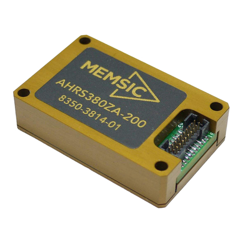
Memsic IMU380ZA User manual

Precision Farming
Antenna Stabilization
Power Sensing Solutions for a Better Life
IMU380ZA
INERTIAL MEASUREMENT SYSTEM
The MEMSIC IMU380ZA is a miniature fully-
calibrated inertial measurement system designed for
demanding embedded applications that require a
complete dynamic measurement solution in a robust
low-profile package. The IMU380ZA provides a
standard SPI bus for cost-effective board-to-board
communications.
Features
Complete 6DOF Inertial System
Optional 3-Axis Magnetometer
Standard and High Range Options
SPI (or UART) Interface
Update Rate, 1Hz to 200Hz
1KHz Clock Synch Input
Miniature Package, 24 x 37 x 9.5 mm
Lightweight < 17 g
Low Power Consumption < 250 mW
Wide Temp Range, -40C to +85C
High Reliability, MTBF > 50k hours
The MEMSIC IMU380ZA integrates highly-reliable MEMS
6DOF inertial sensors (optional 3-axis magnetic sensors) in
a miniature factory-calibrated module to provide consistent
performance through the extreme operating environments
in a wide variety of dynamic control and navigation
applications.
Applications
Precision Farming
Platform Stabilization
Unmanned Vehicle Control
Robotics Control
Document P/N: 6020-3810-03

Performance
IMU380ZA (-200,-209,-409)
Angular Rate
Range: Roll, Pitch, Yaw (º/sec)
± 200 (± 400 High Range Model)
Bias Instability (º/hr) 1,2
< 10
Bias Stability Over Temp (º/sec)
< 0.5
Resolution (º/sec)
< 0.02
Scale Factor Accuracy (%)
< 0.1
Non-Linearity (%FS)
< 0.1
Angle Random Walk (º/√hr) 2
< 0.75
Bandwidth (Hz)
5-50 (user-configurable)
Acceleration
Range: X, Y Z (g)
± 4 (± 8 High Range Model)
Bias Instability (mg) 1,2
< 0.02
Bias Stability Over Temp (mg)
< 5
Resolution (mg)
< 0.5
Scale Factor Accuracy (%)
< 0.1
Non-Linearity (%FS)
< 0.1
Velocity Random Walk (m/s/√hr) 2
< 0.05
Bandwidth (Hz)
5-50 (user-configurable)
Magnetic Field
Range: X, Y Z (Gauss)
± 4
Resolution (mGauss)
< 5
Noise Density (mGauss /√Hz)
< 1
Bandwidth (Hz)
5
Specifications
Environment
Operating Temperature (ºC)
-40 to +85
Non-Operating Temperature (ºC)
-55 to +105
Enclosure
Aluminum (Gold Anodized)
Electrical
Input Voltage (VDC)
3.0 to 5.5
Power Consumption (mW)
< 250
Digital Interface
SPI or UART (user-configurable)
Output Data Rate
1Hz to 200Hz (user-configurable)
Input Clock Sync
1kHz Sync Pulse
Physical
Size (mm)
24.15 x 37.7 x 9.5
Weight (gm)
< 17
Interface Connector
20-Pin (10 x 2) 1.0 mm pitch header
Ordering Information
Model
Description
IMU380ZA-200
6DOF OEM IMU
IMU380ZA-209
9DOF OEM IMU
IMU380ZA-409
9DOF OEM High Range IMU
EVAL-KIT DMU380ZA-200
DMU380ZA-200 Low Range Evaluation Kit
EVAL-KIT DMU380ZA-400
DMU380ZA-400 High Range Evaluation Kit
IMU380ZA
INERTIAL MEASUREMENT SYSTEM
NAV-VIEW
Configuration and Display Software
This product has been developed exclusively for commercial applications. It has not been tested
for, and makes no representation or warranty as to conformance with, any military specifications
or its suitability for any military application or end-use. Additionally, any use of this product for
nuclear, chemical or biological weapons, or weapons research, or for any use in missiles,
rockets, and/or UAV’s of 300km or greater range, or any other activity prohibited by the Export
Administration Regulations, is expressly prohibited without the written consent and without
obtaining appropriate US export license(s) when required by US law. Diversion contrary to U.S.
law is prohibited. Specifications are subject to change without notice.
1Allan Variance Curve, constant temperature. 21-sigma error.
Support
For more detailed information
please refer to the DMU380ZA-
Series User’s Manual available
online at:
www.memsic.com/support
NAV-VIEW provides an easy to use
graphical interface to display, record,
playback, and analyze all of the
IMU380ZA Inertial Measurement
System parameters.
NAV-VIEW can also be used to set a
wide range of user-configurable fields
in the IMU380ZA to optimize the
system performance for highly
dynamic applications.
NAV-VIEW software is available for
download from MEMSIC’s website at:
www.memsic.com/support
Other Components
The IMU380ZA evaluation kits include
an IMU380ZA, evaluation board, and
USB cable allowing direct connection
to a PC for use with NAV-VIEW
display and configuration software.
Document P/N: 6020-3810-03

DMU380ZA Series
USER MANUAL
Document Part Number: 7430-3810-02
MEMSIC, Inc., 1759 McCarthy Blvd, Milpitas, CA 95035
Tel: 408-964-9700, Fax: 408-854-7702

WARNING
This product has been developed by MEMSIC exclusively for commercial applications. It
has not been tested for, and MEMSIC makes no representation or warranty as to
conformance with, any military specifications or that the product is appropriate for any
military application or end-use. Additionally, any use of this product for nuclear,
chemical, biological weapons, or weapons research, or for any use in missiles, rockets,
and/or UAV's of 300km or greater range, or any other activity prohibited by the Export
Administration Regulations, is expressly prohibited without the written consent of
MEMSIC and without obtaining appropriate US export license(s) when required by US
law. Diversion contrary to U.S. law is prohibited.
©2014 MEMSIC, Inc. All rights reserved. Information in this document is subject to
change without notice.
MEMSIC, SoftSensor, INS380ZA, AHRS380ZA, VG380ZA, and IMU380ZA are
registered trademarks of MEMSIC, Inc. Other product and trade names are trademarks or
registered trademarks of their respective holders.

DMU380ZA Series User’s Manual
Doc# 7430-3810 Rev. 02
Page i
Table of Contents
1Introduction..................................................................................................................1
Manual Overview .................................................................................................11.1
Overview of the DMU380ZA Series Inertial Systems .........................................21.2
2Interface .......................................................................................................................4
Electrical Interface................................................................................................42.1
2.1.1 Connector and Mating Connector..................................................................4
2.1.2 Power Input and Power Input Ground...........................................................5
2.1.3 Serial Data Interface......................................................................................5
2.1.4 External GPS Aiding (VG380ZA, AHRS380ZA and INS380ZA)...............5
2.1.5 Reserved –Factory Use Only........................................................................6
Mechanical Interface.............................................................................................62.2
3Theory of Operation.....................................................................................................7
DMU380ZA Series Default Coordinate System.................................................113.1
3.1.1 Advanced Settings.......................................................................................12
IMU380ZA Theory of Operation........................................................................123.2
3.2.1 IMU380ZA Advanced Settings...................................................................13
3.2.2 IMU380ZA Built-In Test.............................................................................14
VG380ZA Theory of Operation..........................................................................143.3
3.3.1 VG380ZA Advanced Settings.....................................................................16
4.3.2 VG380ZA Built-In Test..............................................................................17
AHRS380ZA Theory of Operation.....................................................................183.4
3.4.1 AHRS380ZA Magnetometer Calibration and Alignment ...........................19
3.4.2 AHRS380ZA Advanced Settings................................................................21
3.4.3 AHRS380ZA Built-In Test..........................................................................22
INS380ZA Theory of Operation.........................................................................233.5
3.5.1 INS380ZA Magnetometer Calibration and Alignment ...............................25
3.5.2 INS380ZA Advanced Settings ....................................................................25
3.5.3 INS380ZA Built-In Test..............................................................................26
4Application Guide......................................................................................................28
Introduction.........................................................................................................284.1
Fixed Wing Aircraft............................................................................................284.2
Rotorcraft............................................................................................................294.3
Land Vehicle.......................................................................................................294.4
Water Vehicle.....................................................................................................304.5
5DMU380ZA SPI Port Interface Definition................................................................32

DMU380ZA Series User’s Manual
Page ii
Doc# 7430-3810 Rev. 02
DMU380ZA Register Map.................................................................................325.1
DMU380ZA SPI Register Read Methodology...................................................335.2
5.2.1 DMU380ZA SPI Port Polled-Mode Read...................................................34
5.2.2 DMU380ZA SPI Port Burst-Mode Read.....................................................35
Output Data Registers.........................................................................................375.3
System Registers.................................................................................................375.4
Diagnostic Status Register..................................................................................385.5
DMU380ZA SPI Register Write Methodology..................................................385.6
Configuration Registers......................................................................................405.7
5.7.1 Self-Test/Data-Ready ..................................................................................40
5.7.2 Output Data Rate/Clock Configuration.......................................................40
5.7.3 Rate-Sensor Scaling/Low-Pass Filter..........................................................41
5.7.4 Magnetic-Alignment....................................................................................42
Suggested Operation...........................................................................................435.8
6DMU380 UART Port Interface Definition................................................................46
General Settings..................................................................................................466.1
Number Formats.................................................................................................466.2
Packet Format.....................................................................................................476.3
6.3.1 Packet Header..............................................................................................47
6.3.2 Packet Type .................................................................................................47
6.3.3 Payload Length............................................................................................48
6.3.4 Payload........................................................................................................48
6.3.5 16-bit CRC-CCITT......................................................................................48
6.3.6 Messaging Overview...................................................................................48
7DMU380 Standard UART Port Commands and Messages.......................................51
Link Test.............................................................................................................517.1
7.1.1 Ping Command............................................................................................51
7.1.2 Ping Response..............................................................................................51
7.1.3 Echo Command ...........................................................................................51
7.1.4 Echo Response.............................................................................................51
Interactive Commands........................................................................................51
7.2
7.2.1 Get Packet Request......................................................................................51
7.2.2 Algorithm Reset Command.........................................................................52
7.2.3 Algorithm Reset Response ..........................................................................52
7.2.4 Calibrate Command.....................................................................................52
7.2.5 Calibrate Acknowledgement Response.......................................................53
7.2.6 Calibration Completed Parameters Response..............................................53

DMU380ZA Series User’s Manual
Doc# 7430-3810 Rev. 02
Page iii
7.2.9 Error Response ............................................................................................54
Output Packets (Polled) ......................................................................................54
7.3
7.3.1 Identification Data Packet ...........................................................................54
7.3.2 Version Data Packet ....................................................................................54
7.3.3 Test 0 (Detailed BIT and Status) Packet......................................................55
Output Packets (Polled or Continuous)...............................................................557.4
7.4.1 Scaled Sensor Data Packet 0 .......................................................................55
7.4.2 Scaled Sensor Data Packet 1 (Default IMU Data).......................................56
7.4.3 Angle Data Packet 1 (Default AHRS Data) ................................................57
7.4.4 Angle Data Packet 2 (Default VG Data) .....................................................58
7.4.5 Nav Data Packet 0 .......................................................................................59
7.4.6 Nav Data Packet 1 (Default INS Data)........................................................60
7.4.7 Angle Data Packet B1 (Custom VG Data)..................................................61
7.4.8 Angle Data Packet B2 (Custom VG Data)..................................................62
8DMU380ZA Advanced UART Port Commands .......................................................63
Configuration Fields...........................................................................................638.1
Continuous Packet Type Field............................................................................638.2
Digital Filter Settings..........................................................................................648.3
Orientation Field.................................................................................................648.4
User Behavior Switches......................................................................................668.5
Hard and Soft Iron Values..................................................................................668.6
Heading Track Offset..........................................................................................668.7
Commands to Program Configuration................................................................678.8
8.8.1 Write Fields Command................................................................................67
8.8.2 Set Fields Command....................................................................................68
Read Fields Command........................................................................................698.9
Read Fields Response .....................................................................................698.10
Get Fields Command.......................................................................................698.11
Get Fields Response........................................................................................708.12
9DMU380ZA Advanced UART Port BIT...................................................................71
Built In Test (BIT) and Status Fields..................................................................719.1
Master BIT and Status (BITstatus) Field............................................................739.2
hardwareBIT Field..............................................................................................749.3
hardwarePowerBIT Field....................................................................................749.4
hardwareEnvironmentalBIT Field ......................................................................749.5
comBIT Field......................................................................................................749.6

DMU380ZA Series User’s Manual
Page iv
Doc# 7430-3810 Rev. 02
comSerialABIT Field..........................................................................................759.7
comSerialBBIT Field..........................................................................................759.8
softwareBIT Field...............................................................................................759.9
softwareAlgorithmBIT Field...........................................................................769.10
softwareDataBIT Field....................................................................................769.11
hardwareStatus Field.......................................................................................769.12
comStatus Field...............................................................................................779.13
softwareStatus Field........................................................................................779.14
sensorStatus Field............................................................................................779.15
Configuring the Master Status.........................................................................779.16
9.16.1 hardwareStatusEnable Field ........................................................................78
9.16.2 comStatusEnable Field................................................................................78
9.16.3 softwareStatusEnable Field .........................................................................78
9.16.4 sensorStatusEnable Field.............................................................................78
10 Warranty and Support Information ........................................................................79
10.3.1 Authorization...............................................................................................79
10.3.2 Identification and Protection .......................................................................79
10.3.3 Sealing the Container...................................................................................80
10.3.4 Marking .......................................................................................................80
10.3.5 Return Shipping Address.............................................................................80
Appendix A: Installation and Operation of NAV-VIEW..................................................81
NAV-VIEW Computer Requirements...........................................................................81
Install NAV-VIEW ....................................................................................................81
Connections ...................................................................................................................81
Setting up NAV-VIEW..................................................................................................82
Data Recording..............................................................................................................82
Data Playback................................................................................................................83
Raw Data Console .........................................................................................................83
Horizon and Compass View..........................................................................................84
Packet Statistics View....................................................................................................85
Unit Configuration.........................................................................................................85
Advanced Configuration................................................................................................86
Bit Configuration...........................................................................................................87
Mag Alignment Procedure.............................................................................................88
Hard Iron/Soft Iron Overview....................................................................................88
Mag Alignment Procedure Using NAV-VIEW.........................................................89
Read Unit Configuration................................................................................................91

DMU380ZA Series User’s Manual
Doc# 7430-3810 Rev. 02
Page v
Appendix B: NMEA Message Format..............................................................................93
GGA - GPS fix data.......................................................................................................93
Appendix C: Sample Packet-Parser Code.........................................................................95
Overview........................................................................................................................95
Code listing....................................................................................................................96
Appendix D: Sample Packet Decoding...........................................................................102

DMU380ZA Series User’s Manual
Page vi
Doc# 7430-3810 Rev. 02
About this Manual
The following annotations have been used to provide additional information.
NOTE
Note provides additional information about the topic.
EXAMPLE
Examples are given throughout the manual to help the reader understand the terminology.
IMPORTANT
This symbol defines items that have significant meaning to the user
WARNING
The user should pay particular attention to this symbol. It means there is a chance that
physical harm could happen to either the person or the equipment.
The following paragraph heading formatting is used in this manual:
1 Heading 1
1.1 Heading 2
1.1.1 Heading 3
Normal

DMU380ZA Series User’s Manual
________________________________________________________________________
Doc# 7430-3810 Rev.02 Page 1
1Introduction
Manual Overview1.1
This manual provides a comprehensive introduction to MEMSIC’s DMU380ZA Series
Inertial System products (Dynamic Measurement Unit 380ZA). For users wishing to get
started quickly, please refer to the two-page quick start guide included with each
evaluation kit shipment. Table 1 highlights the content in each section and suggests how
to use this manual.
Table 1 Manual Content
Manual Section
Who Should Read?
Section 1:
Manual Overview
All customers should read sections 1.1 and 1.2.
Section 2:
Interface
Customers designing the electrical and mechanical interface to the DMU380ZA
series products should read Section 2.
Section 3:
Theory of Operation
All customers should read Section 3.
As the DMU380ZA Series products are inter-related, use the chart at the
beginning of Section 3 to ensure that you get an overview of all of the functions
and features of your DMU380ZA Series system. For example, if you have
purchased an INS380ZA, you should read not only the section on the INS380ZA,
but also familiarize yourself with the theory of operation for the IMU380ZA,
VG380ZA, and AHRS380ZA. The INS380ZA builds on the capabilities of the
IMU380ZA, VG380ZA and AHRS380ZA.
Section 4:
Application Guide
Customers who want product configuration tips for operating the DMU380ZA
Series Inertial Systems in a wide range of applications –fixed wing, rotary wing,
unmanned vehicles, land vehicles, marine vessels, and more, should review the
part of Section 4 that is relevant to your application. Note: INS and AHRS
DMU380ZA Series units are preconfigured for airborne applications with
“normal” dynamics. VG380ZA Series units are preconfigured for land
applications with “automotive testing” dynamics. All DMU380ZA Series products
allow for complete flexibility in configuration by the user.
Section 5:
SPI Port Interface
Customers designing the software interface to the DMU380ZA series products
SPI Port should review Section 5.
Section 6-9:
UART Port Interface
Customers designing the software interface to the DMU380ZA series products
UART Port should review Sections 6-9.

DMU380ZA Series User’s Manual
________________________________________________________________________
Doc# 7430-3810 Rev. 02 Page 2
Overview of the DMU380ZA Series Inertial Systems1.2
This manual provides a comprehensive introduction to the use of MEMSIC’s
DMU380ZA Series Inertial System products listed in Table 2. This manual is intended to
be used as a detailed technical reference and operating guide. MEMSIC’s DMU380ZA
Series products combine the latest in high-performance commercial MEMS (Micro-
electromechanical Systems) sensors and digital signal processing techniques to provide a
small, cost-effective alternative to existing IMU systems.
Table 2 DMU380ZA Series Feature Description
Product
Features
IMU380ZA (-200,-209,-409)
6-DOF Digital IMU, 9-DOF Digital IMU Standard Range, 9-DOF Digital IMU High Range
VG380ZA (-200,-400)
6-DOF IMU plus Roll and Pitch Standard Range, High Range
AHRS380ZA (-200, -400)
9-DOF IMU (3-Axis Internal Magnetometer) plus Roll, Pitch, and Heading Standard Range,
High Range
INS380ZA (-200, -400)
9-DOF IMU (3-Axis Internal Magnetometer) with interface for External GPS Receiver plus
Position, Velocity, Roll, Pitch, and Heading Standard Range, High Range
The DMU380ZA Series is MEMSIC’s fourth generation of MEMS-based Inertial
Systems, building on over a decade of field experience, and encompassing thousands of
deployed units and millions of operational hours in a wide range of land, marine,
airborne, and instrumentation applications. It is designed for OEM applications.
At the core of the DMU380ZA Series is a rugged 6-DOF (Degrees of Freedom) MEMS
inertial sensor cluster that is common across all members of the DMU380ZA Series. The
6-DOF MEMS inertial sensor cluster includes three axes of MEMS angular rate sensing
and three axes of MEMS linear acceleration sensing. These sensors are based on rugged,
field proven silicon bulk micromachining technology. Each sensor within the cluster is
individually factory calibrated for temperature and non-linearity effects during
MEMSIC’s manufacturing and test process using automated thermal chambers and rate
tables.
Coupled to the 6-DOF MEMS inertial sensor cluster is a high performance
microprocessor that utilizes the inertial sensor measurements to accurately compute
navigation information including attitude, heading, and linear velocity thru dynamic
maneuvers (actual measurements are a function of the DMU380ZA Series product as
shown in Table 2). In addition, the processor makes use of internal magnetic sensor and
external GPS data to aid the performance of the inertial algorithms and help correct long
term drift and estimate errors from the inertial sensors and computations. The navigation
algorithm utilizes a multi-state configurable Extended Kalman Filter (EKF) to correct for
drift errors and estimate sensor bias values.
Another unique feature of the DMU380ZA Series is the extensive field configurability of
the units. This field configurability allows the DMU380ZA Series of Inertial Systems to
satisfy a wide range of applications and performance requirements with a single mass
produced hardware platform. The basic configurability includes parameters such as baud
rate (UART), clock speed (SPI), packet type, and update rate, and the advanced
configurability includes the defining of custom axes and how the sensor feedback is
utilized in the Kalman filter during the navigation process.
The DMU380ZA Series is packaged in a light-weight, rugged, unsealed metal enclosure
that is designed for cost-sensitive commercial and OEM applications. The DMU380 can
be configured to output data over a SPI Port or a low level UART serial port. The port

DMU380ZA Series User’s Manual
________________________________________________________________________
Doc# 7430-3810 Rev.02 Page 3
choice is user controlled by grounding the appropriate pin on the connector. The
DMU380 low level UART output data port is supported by MEMSIC’s NAV-VIEW 3.X,
a powerful PC-based operating tool that provides complete field configuration,
diagnostics, charting of sensor performance, and data logging with playback.

DMU380ZA Series User’s Manual
________________________________________________________________________
Doc# 7430-3810 Rev. 02 Page 4
2Interface
Electrical Interface2.1
2.1.1 Connector and Mating Connector
The DMU380ZA main connector is a SAMTEC FTM-110-02-F-DV-P defined in Figure
1. The mating connector that can be used is the SAMTEC CLM-110-02.
Figure 1 DMU380ZA Interface Connector
The connector pin definitions are defined in Table 3.
Table 3 DMU380ZA Interface Connector Pin Definition
Pin
Signal
1
Reserved –factory use only
2
Synchronization Input (1KHz Pulse used to synchronize SPI Com) / 1PPS
3
SPI Clock (SCLK) / UART TX
4
SPI Data Output (MISO) / UART RX
5
SPI Data Input (MOSI)
6
SPI Chip Select (SS)
7
Data Ready (SPI Communication Data Ready) / SPI-UART Port Select
8
External Reset (NRST)
9
Reserved –factory use only
10
Power VIN (3-5 VDC)
11
Power VIN (3-5 VDC)
12
Power VIN (3-5 VDC)
13
Power GND
14
Power GND
15
Power GND
16
Reserved –factory use only
17
Reserved –factory use only
18
Reserved –factory use only

DMU380ZA Series User’s Manual
________________________________________________________________________
Doc# 7430-3810 Rev.02 Page 5
19
Reserved –factory use only
20
Reserved –factory use only
2.1.2 Power Input and Power Input Ground
Power is applied to the DMU380ZA on pins 10 through 15. Pins 13-15 are ground; Pins
10-12 accepts 3 to 5 VDC unregulated input. Note that these are redundant power ground
input pairs.
WARNING
Do not reverse the power leads or damage may occur.
2.1.3 Serial Data Interface
The user can select the serial interface used with the DMU380ZA by controlling the logic
level on connector pin 7 at system startup. If pin 7 is left floating then the DMU380ZA is
configured for SPI communications on pins 3-6. Pin 7 is set as an output and used as the
DATA READY discrete for SPI communications. Additionally, the user can synchronize
the output data on the SPI port by providing a 1 KHz input pulse on Pin 2. For the
complete SPI interface definition, please refer to Section 5.
If the connector pin 7 is grounded then the DMU380ZA is configured for low-level
UART output on pins 3 and 4. This is a standard UART asynchronous output data port.
For the complete UART interface definition, please refer to Sections 6-8. Note that the
two output port interface methods are controlled independently from each other. The
UART port output controls apply only to data being output over the UART port, and the
SPI output controls apply only to data being output over the SPI port.
2.1.4 External GPS Aiding (VG380ZA, AHRS380ZA and INS380ZA)
The VG380ZA/AHRS380ZA/INS380ZA allows the use of an external GPS receiver to
be connected the secondary UART port. The user is required to configure the GPS
receiver to output the GPS messages that the DMU380ZA Series expects. Table 4 shows
the supported GPS protocols and guidelines for configuration. Note that the details of the
GPS messages can be found in the respective GPS protocol documents. The user must
configure the VG/AHRS/INS380ZA to accept external GPS information using NAV-
VIEW as described in Appendix A. If the VG/AHRS/INS380ZA is parsing valid
external GPS data and the GPS receiver has 3D lock, then the comStatus
noExternalGPS flag will be zero, otherwise it will be one. See Section 9 for a complete
description of system status indications.
Since NMEA protocol does not provide vertical velocity, the vertical velocity that the
DMU380ZA Series estimates (based upon GPS altitude changes) may not be sufficient
for airborne applications (see Table 4). Therefore, the NMEA protocol is not
recommended for airborne applications.
Table 4 External GPS Receiver for VG/AHRS/INS380ZA
Protocols
Required Messages
Required Message Rate
Baud rate
Ublox binary
NAV-LLH, NAV-VELNED,
NAV-STATUS
4 Hz
9600, 19200, 38400,
57600
NovAtel OEM4 and
OEMV Binary
BestPosB, BestVelB
4Hz
9600, 19200, 38400,
57600
NovAtel OEM4
ASCII
PosVelNavDopA
4Hz
19200, 38400, 57600**

DMU380ZA Series User’s Manual
________________________________________________________________________
Doc# 7430-3810 Rev. 02 Page 6
NMEA*
GPGGA, GPVTG
4Hz
9600, 19200, 38400,
57600
*Not recommended for airborne applications.
**57600 is the preferred baud rate for optimum performance
The secondary UART port should be configured to 8 data bits, 1 start bit, 1 stop bit, no
parity bit, and no flow control.
2.1.4.1 1 PPS Input Interface
When using external GPS aiding for a VG/AHRS/INS380ZA system, Pin 2 should be
used for the 1PPS input signal to force synchronization of sensor data collection to a 1Hz
rising-edge signal. The signal must maintain 0.0-0.2 V zero logic and 3.0-5.0 volts high
logic and stay within 100ms of the internal system 1 second timing. Sending this signal
to the system will align the sensor data collection and algorithm processing to its rising
edge and 10ms boundaries thereafter. When the system is synchronized to 1PPS, the
hardwareStatusunlocked1PPS flag will be zero; otherwise, it will be one.
2.1.4.2 SPI Com Synchronization Input
If the user does not have 1PPS available from an external GPS receiver, then Pin 2 can be
used as a sync pulse to force synchronization of sensor data collection to a 1 KHz rising-
edge signal for output over the SPI port.
2.1.4.3 External GPS Receiver Antenna Connection
The external GPS receiver needs to receive signals from as many satellites as possible. A
GPS receiver doesn’t work properly in narrow streets and underground parking lots or if
objects or human beings cover the antenna. Poor visibility may result in position drift or a
prolonged Time-To-First-Fix (TTFF). A good sky visibility is therefore a prerequisite.
Even the best receiver can’t make up for signal loss due to a poor antenna, in-band
jamming or a poor RF cable. Placing the antenna on a 4 inch or larger ground plane is
highly recommended.
IMPORTANT
Place the antenna with optimal sky visibility and use a ground plane. Route the GPS
Antenna RF cable away from sources of radiated energy (i.e. switching power supplies).
2.1.5 Reserved –Factory Use Only
During normal operation of the DMU380ZA, no connection is made to the Reserved –
factory use only pins. These pins have internal pull-up mechanisms and must have no
connections for the DMU380ZA to operate properly.
Mechanical Interface2.2
The DMU380ZA mechanical interface is defined by the outline drawing in Figure 2.

DMU380ZA Series User’s Manual
________________________________________________________________________
Doc# 7430-3810 Rev.02 Page 7
Figure 2 DMU380ZA Outline Drawing
NOTES UNLESS OTHERWISE STATED:
1) MATING CONNECTOR SAMTEC CLM-110-02
2) DIMENSION TO CENTROID OF PIN ONE
3Theory of Operation
This section of the manual covers detailed theory of operation for each member of the
DMU380ZA Series starting with the basic IMU380ZA and then reviewing each major
variant (VG, AHRS and INS) with their associated additional features, outputs, and
performance. Table 5 shows the basic features of each member of the DMU380ZA Series
with cross references to important sections for review.
Table 5 DMU380ZA Series Overview
Product
Features
Learning More
IMU380ZA
6-DOF IMU, 9-DOF IMU
Read 3.1 and 3.2
VG380ZA
6-DOF IMU
Roll, Pitch
Read 3.1, 3.2, and 3.3
AHRS380ZA
9-DOF IMU (3-Axis Internal Magnetometer)
Read 3.1, 3.2, 3.3, and 3.4

DMU380ZA Series User’s Manual
________________________________________________________________________
Doc# 7430-3810 Rev. 02 Page 8
Roll, Pitch, and Heading
INS380ZA
9-DOF IMU (3-Axis Internal Magnetometer and external
GPS Receiver)
Position, Dynamic Velocity, Roll, Pitch, and Heading
Read 3.1, 3.2, 3.3, 3.4, and 3.5
Figure 3 shows the DMU380ZA Series hardware block diagram. At the core of the
DMU380ZA Series is a rugged 6-DOF (Degrees of Freedom) MEMS inertial sensor
cluster that is common across all members of the DMU380ZA Series. The 6-DOF MEMS
inertial sensor cluster includes three axes of MEMS angular rate sensing and three axes of
MEMS linear acceleration sensing. These sensors are based on rugged, field proven
silicon bulk micromachining technology. Each sensor within the cluster is individually
factory calibrated using MEMSIC’s automated manufacturing process. Sensor errors are
compensated for temperature bias, scale factor, non-linearity and misalignment effects
using a proprietary algorithm from data collected during manufacturing. Accelerometer
and rate gyro sensor bias shifts over temperature (-40 0C to +71 0C) are compensated and
verified using calibrated thermal chambers and rate tables.
The 6-DOF inertial sensor cluster data is fed into a high speed signal processing chain,
which provides the sensor compensation and digital filtering. The processor also
calculates attitude and navigation data for the appropriate models (VG, AHRS and INS).
Measurement data packets are available at fixed continuous output rates or on a polled
basis from the SPI port or the UART port. The SPI port outputs data via registers, and
the user can perform polled reads of each register, or a block burst read of a set of
predefined registers. Output data over the SPI port can be synchronized to an external 1
KHz pulse. Alternatively, users can input a 1 PPS signal from an external GPS receiver
when providing external GPS data over the secondary UART2 port. The complete SPI
interface is defined in Section 4. The UART port outputs data packets are asynchronous
and defined in Sections 5-7. As shown in the block diagram (Figure 3), the INS380ZA
and AHRS380ZA include an internal 3-axis magnetometer.

DMU380ZA Series User’s Manual
________________________________________________________________________
Doc# 7430-3810 Rev.02 Page 9
Figure 3 DMU380ZA Series Hardware Block Diagram
Figure 4 shows the software block diagram. The 6-DOF inertial sen sor cluster data is
fed into a high speed 200Hz signal processing chain. These 6-DOF signals pass through
one or more of the processing blocks and these signals are converted into output
measurement data as shown. Measurement data packets are available at fixed continuous
output rates or on a polled basis. The type of measurement data packets available depends
on the unit type according to the software block diagram and Table 5. Aiding sensor data
is used by an Extended Kalman Filter (EKF) for drift correction in the INS, AHRS and
VG Series products. Built-In-Test and Status data is available in the measurement packet
or via the special Status Packet T0.
As shown in the software block diagram, the DMU380ZA Series has a unit setting and
profile block which configures the algorithm to user and application specific needs. This
feature is one of the more powerful features in the DMU380ZA Series architecture as it
allows the DMU380ZA Series to work in a wide range of commercial applications by
settings different modes of operation for the DMU380ZA Series.
6-DOF Sensor
Cluster
X / Y / Z
Gyros
X / Y / Z
Accelerometers
High-Speed
Sampling &
+
Sensor
Compensation /
Filtering
+
Navigation &
Attitude
Kalman Filter
UART1
SPI
UART2
System Digital Outputs and Inputs
UART1 (Pins 3,4) or SPI (Pins 3-6)
MEMSIC Serial Protocol (UART1)
SPI Registers (SPI)
X / Y / Z Acceleration
Roll / Pitch / Yaw Rate
X / Y / Z Magnetic Fields (INS/AHRS only)
Temperature
Sensor
X / Y / Z
Magnetometers
UART2 External GPS Input
(VG/AHRS/INS)
SPI Com Sync 1 KHz Pulse
External GPS 1 PPS Input
Pin 2

DMU380ZA Series User’s Manual
________________________________________________________________________
Doc# 7430-3810 Rev. 02 Page 10
Figure 4 DMU380ZA Series Software Block Diagram
Simplified functional block diagrams for INS, AHRS and VG series products derived
from Figure 4 are shown in Figure 5 to highlight key features of each product. The
DMU380ZA Series products are mainly differentiated by types of aiding sensors used in
the EKF for the drift correction of the 6-DOF inertial sensor cluster.
For the AHRS product, a 3-axis magnetometer is used for correcting the drift on
yaw/heading angle. For the INS product, a 3-axis magnetometer and a GPS receiver are
used for correcting the drift on yaw/heading angle, increasing the accuracy of the attitude
estimation by incorporating these sensor signals into the EKF, and providing a navigation
solution. The common aiding sensor for the drift correction for the attitude (i.e., roll and
pitch only) is a 3-axis accelerometer. This is the default configuration for the VG product.
X / Y / Z Body
Accelerometers
6-DOF Sensor Cluster
Sensor
Calibration
Axes Rotation
GPS Data
Internal/External
Kalman
Filter and Dynamic State Model
Integration to 100 Hz
Velocity, GPS
Position Output
Hard/Soft Iron
Calibration
UseMags
X / Y / Z
Magnetometers
INS/AHRS only
IMU
-
Scaled Packets
(S0, S1)
All Units
INS/AHRS/VG/IMU
Gravity Reference
Turn Rate
(Internal
Computation)
Free Integrate
TurnSwitch
Threshold
UseGPS
Stationary Yaw
Lock
X / Y / Z Body
Rates
200Hz
Signal
Proc.
Chain
Extended Kalman Filter (EKF)
Drift Correction Module
VG/AHRS
–
Angle
Packets
(A1, A2)
INS/AHRS/VG
INS
-
Nav
Packets
(N0, N1)
INS/AHRS/VG
Integration to
Attitude
Unit Settings & Profile*
Communication Settings
Axes Orientation
Low Pass Filtering
Free Integrate
UseGPS
UseMags
TurnSwitch
Threshold
DynamicMotion
Restart On
Overange
Dynamic Motion
Programmable BIT Alerts
Aiding Sensors
Built In Test
& Status
Data
Available to
User
Measurement
Data Available to
User (Fixed Rate
or Polled)
Status
Packet
(T0)
Table of contents
Other Memsic Measuring Instrument manuals