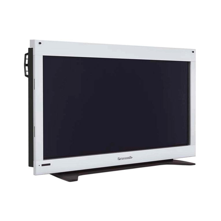
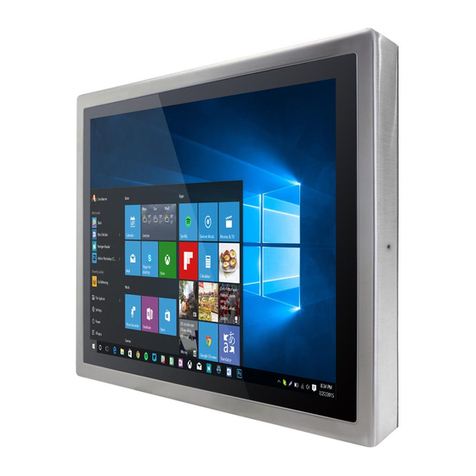
MEN DC19 User manual

User Manual
DC19
Rugged 10.4" Panel PC with Touch Screen
Rugged EN50155 Train Display Computer
2020-10-2720DC19-00 E1

20DC19-00 E1 2020-10-27 2
Contents
Contents
Contents. . . . . . . . . . . . . . . . . . . . . . . . . . . . . . . . . . . . . . . . . . . . . . . . . . . . . . . . . . 2
About this Document . . . . . . . . . . . . . . . . . . . . . . . . . . . . . . . . . . . . . . . . . . . . . . 6
Product Safety . . . . . . . . . . . . . . . . . . . . . . . . . . . . . . . . . . . . . . . . . . . . . . . . . . . . 8
Product Compliance . . . . . . . . . . . . . . . . . . . . . . . . . . . . . . . . . . . . . . . . . . . . . . . 9
Disclaimer . . . . . . . . . . . . . . . . . . . . . . . . . . . . . . . . . . . . . . . . . . . . . . . . . . . . . . . 10
Contacts . . . . . . . . . . . . . . . . . . . . . . . . . . . . . . . . . . . . . . . . . . . . . . . . . . . . . . . . . 11
1 Product Overview . . . . . . . . . . . . . . . . . . . . . . . . . . . . . . . . . . . . . . . . . . . . . . 12
1.1 Product Description . . . . . . . . . . . . . . . . . . . . . . . . . . . . . . . . . . . . . . . . . . . . . . .12
1.2 Product Architecture . . . . . . . . . . . . . . . . . . . . . . . . . . . . . . . . . . . . . . . . . . . . . .13
1.2.1 Interfaces. . . . . . . . . . . . . . . . . . . . . . . . . . . . . . . . . . . . . . . . . . . . . . . .13
1.2.2 Functions. . . . . . . . . . . . . . . . . . . . . . . . . . . . . . . . . . . . . . . . . . . . . . . .15
1.3 Technical Data . . . . . . . . . . . . . . . . . . . . . . . . . . . . . . . . . . . . . . . . . . . . . . . . . . . .16
1.4 Cooling Concept . . . . . . . . . . . . . . . . . . . . . . . . . . . . . . . . . . . . . . . . . . . . . . . . . .19
1.5 Product Identification. . . . . . . . . . . . . . . . . . . . . . . . . . . . . . . . . . . . . . . . . . . . . .20
2 Getting Started . . . . . . . . . . . . . . . . . . . . . . . . . . . . . . . . . . . . . . . . . . . . . . . . 21
2.1 Unpacking the DC19. . . . . . . . . . . . . . . . . . . . . . . . . . . . . . . . . . . . . . . . . . . . . . .21
2.2 Configuring the Hardware. . . . . . . . . . . . . . . . . . . . . . . . . . . . . . . . . . . . . . . . . .22
2.2.1 Installing a micro-SIM Card. . . . . . . . . . . . . . . . . . . . . . . . . . . . . . . . . 22
2.3 Mounting the DC19. . . . . . . . . . . . . . . . . . . . . . . . . . . . . . . . . . . . . . . . . . . . . . . .24
2.3.1 Safety Instructions for Mounting . . . . . . . . . . . . . . . . . . . . . . . . . . . . 24
2.3.2 Panel Mounting . . . . . . . . . . . . . . . . . . . . . . . . . . . . . . . . . . . . . . . . . .25
2.4 Connecting and Starting . . . . . . . . . . . . . . . . . . . . . . . . . . . . . . . . . . . . . . . . . . .26
2.4.1 Safety Instructions for Connection . . . . . . . . . . . . . . . . . . . . . . . . . .26
2.4.2 Connecting an Earthing Cable . . . . . . . . . . . . . . . . . . . . . . . . . . . . . .26
2.4.3 Connecting Peripherals. . . . . . . . . . . . . . . . . . . . . . . . . . . . . . . . . . . . 27
2.4.4 Connecting the Power Supply . . . . . . . . . . . . . . . . . . . . . . . . . . . . . .28
2.4.5 Starting Up the System . . . . . . . . . . . . . . . . . . . . . . . . . . . . . . . . . . . .28
2.5 Installing Operating System Software . . . . . . . . . . . . . . . . . . . . . . . . . . . . . . . .28
2.5.1 MDIS System Package . . . . . . . . . . . . . . . . . . . . . . . . . . . . . . . . . . . . . 28
2.6 Using the DC19 under Linux . . . . . . . . . . . . . . . . . . . . . . . . . . . . . . . . . . . . . . . .29
2.6.1 Linux Support for Individual Functions. . . . . . . . . . . . . . . . . . . . . . .29
2.6.2 Configuring Display Backlight/Button Light and LED Settings. . . . 30
2.6.3 Accessing SMBus/I2C Devices using duagon Tools. . . . . . . . . . . . . 32
2.6.4 Accessing SMBus/I2C Devices using Standard Linux I2C Tools. . . 34
2.6.5 Managing RTC Time Adjustments . . . . . . . . . . . . . . . . . . . . . . . . . . .34
2.6.6 Enabling the Alarm Buzzer . . . . . . . . . . . . . . . . . . . . . . . . . . . . . . . . . 35
2.6.7 Switching between RS232 and RS422/RS485 Interface . . . . . . . . . 36
2.7 Using the DC19 under Windows. . . . . . . . . . . . . . . . . . . . . . . . . . . . . . . . . . . . .37
2.7.1 Windows Support for Individual Functions . . . . . . . . . . . . . . . . . . .37
2.7.2 Configuring Display Backlight/Button Light and LED Settings. . . . 38
2.7.3 Accessing SMBus/I2C Devices . . . . . . . . . . . . . . . . . . . . . . . . . . . . . .40
2.7.4 Managing RTC Time Adjustments . . . . . . . . . . . . . . . . . . . . . . . . . . .41
2.7.5 Switching the Alarm Buzzer . . . . . . . . . . . . . . . . . . . . . . . . . . . . . . . .41
2.7.6 Switching between RS232 and RS422/RS485 Interface . . . . . . . . . 42

20DC19-00 E1 2020-10-27 3
Contents
3 Functional Description. . . . . . . . . . . . . . . . . . . . . . . . . . . . . . . . . . . . . . . . . . 43
3.1 Power Supply. . . . . . . . . . . . . . . . . . . . . . . . . . . . . . . . . . . . . . . . . . . . . . . . . . . . .43
3.2 Display . . . . . . . . . . . . . . . . . . . . . . . . . . . . . . . . . . . . . . . . . . . . . . . . . . . . . . . . . .43
3.2.1 Light Sensor . . . . . . . . . . . . . . . . . . . . . . . . . . . . . . . . . . . . . . . . . . . . .43
3.3 CPU . . . . . . . . . . . . . . . . . . . . . . . . . . . . . . . . . . . . . . . . . . . . . . . . . . . . . . . . . . . . .44
3.3.1 Processor Core . . . . . . . . . . . . . . . . . . . . . . . . . . . . . . . . . . . . . . . . . . .44
3.4 Trusted Platform Module (TPM) . . . . . . . . . . . . . . . . . . . . . . . . . . . . . . . . . . . . .44
3.5 Supervision and Management . . . . . . . . . . . . . . . . . . . . . . . . . . . . . . . . . . . . . .44
3.5.1 Watchdog . . . . . . . . . . . . . . . . . . . . . . . . . . . . . . . . . . . . . . . . . . . . . . .44
3.5.2 Temperature Measurement . . . . . . . . . . . . . . . . . . . . . . . . . . . . . . . . 44
3.6 Front-Panel LEDs. . . . . . . . . . . . . . . . . . . . . . . . . . . . . . . . . . . . . . . . . . . . . . . . . .45
3.7 Alarm Buzzer . . . . . . . . . . . . . . . . . . . . . . . . . . . . . . . . . . . . . . . . . . . . . . . . . . . . .45
3.8 Real-Time Clock (RTC). . . . . . . . . . . . . . . . . . . . . . . . . . . . . . . . . . . . . . . . . . . . . .46
3.9 Memory . . . . . . . . . . . . . . . . . . . . . . . . . . . . . . . . . . . . . . . . . . . . . . . . . . . . . . . . . 47
3.9.1 System RAM . . . . . . . . . . . . . . . . . . . . . . . . . . . . . . . . . . . . . . . . . . . . .47
3.10 Mass Storage . . . . . . . . . . . . . . . . . . . . . . . . . . . . . . . . . . . . . . . . . . . . . . . . . . . . .47
3.10.1 eMMC. . . . . . . . . . . . . . . . . . . . . . . . . . . . . . . . . . . . . . . . . . . . . . . . . . .47
3.11 Isolation Voltages . . . . . . . . . . . . . . . . . . . . . . . . . . . . . . . . . . . . . . . . . . . . . . . . .48
3.12 Audio. . . . . . . . . . . . . . . . . . . . . . . . . . . . . . . . . . . . . . . . . . . . . . . . . . . . . . . . . . . .49
3.13 USB . . . . . . . . . . . . . . . . . . . . . . . . . . . . . . . . . . . . . . . . . . . . . . . . . . . . . . . . . . . . .50
3.13.1 Rear Connection. . . . . . . . . . . . . . . . . . . . . . . . . . . . . . . . . . . . . . . . . . 50
3.14 Ethernet . . . . . . . . . . . . . . . . . . . . . . . . . . . . . . . . . . . . . . . . . . . . . . . . . . . . . . . . . 51
3.14.1 Rear Connection. . . . . . . . . . . . . . . . . . . . . . . . . . . . . . . . . . . . . . . . . . 51
3.14.2 Signal Mnemonics . . . . . . . . . . . . . . . . . . . . . . . . . . . . . . . . . . . . . . . .51
3.15 Wireless Functionality . . . . . . . . . . . . . . . . . . . . . . . . . . . . . . . . . . . . . . . . . . . . .52
3.15.1 PCI Express Mini Card . . . . . . . . . . . . . . . . . . . . . . . . . . . . . . . . . . . . .52
3.15.2 GNSS (Optional) . . . . . . . . . . . . . . . . . . . . . . . . . . . . . . . . . . . . . . . . . .53
3.15.3 LTE (Optional) . . . . . . . . . . . . . . . . . . . . . . . . . . . . . . . . . . . . . . . . . . . .54
3.15.4 WLAN (Optional). . . . . . . . . . . . . . . . . . . . . . . . . . . . . . . . . . . . . . . . . .54
3.15.5 Antenna Connectors (Optional) . . . . . . . . . . . . . . . . . . . . . . . . . . . . .54
3.15.6 SIM Card Interface . . . . . . . . . . . . . . . . . . . . . . . . . . . . . . . . . . . . . . . .55
3.16 Multifunction Vehicle Bus (MVB) (Optional) . . . . . . . . . . . . . . . . . . . . . . . . . . .57
3.17 Digital I/O . . . . . . . . . . . . . . . . . . . . . . . . . . . . . . . . . . . . . . . . . . . . . . . . . . . . . . . .57
3.18 RS232/RS485/RS422 . . . . . . . . . . . . . . . . . . . . . . . . . . . . . . . . . . . . . . . . . . . . . . .58
3.19 CAN Bus . . . . . . . . . . . . . . . . . . . . . . . . . . . . . . . . . . . . . . . . . . . . . . . . . . . . . . . . . 59
3.19.1 CAN Bus Termination . . . . . . . . . . . . . . . . . . . . . . . . . . . . . . . . . . . . . 59
3.20 Starter Kit . . . . . . . . . . . . . . . . . . . . . . . . . . . . . . . . . . . . . . . . . . . . . . . . . . . . . . . .60
3.20.1 Power Cable . . . . . . . . . . . . . . . . . . . . . . . . . . . . . . . . . . . . . . . . . . . . .60
3.20.2 Ethernet Cable . . . . . . . . . . . . . . . . . . . . . . . . . . . . . . . . . . . . . . . . . . .61
3.20.3 USB Type A Cable. . . . . . . . . . . . . . . . . . . . . . . . . . . . . . . . . . . . . . . . . 62
3.20.4 CAN D-Sub Cable . . . . . . . . . . . . . . . . . . . . . . . . . . . . . . . . . . . . . . . . . 63
3.20.5 RS232/RS422/RS485 D-Sub Cable . . . . . . . . . . . . . . . . . . . . . . . . . . .64
3.20.6 Audio D-Sub Cable . . . . . . . . . . . . . . . . . . . . . . . . . . . . . . . . . . . . . . . .64
3.20.7 Digital I/O D-Sub Cable . . . . . . . . . . . . . . . . . . . . . . . . . . . . . . . . . . . .66
4 Hardware/Software Interface . . . . . . . . . . . . . . . . . . . . . . . . . . . . . . . . . . . 67
4.1 SMBus/I2C Devices . . . . . . . . . . . . . . . . . . . . . . . . . . . . . . . . . . . . . . . . . . . . . . . .67
4.1.1 Digital I/O, Serial Interface, Alarm Buzzer SMB Register (0x40). . .68
4.1.2 Wireless Function and Power Watchdog SMB Register (0x42) ...68
4.2 BMC API (Application Programming Interface). . . . . . . . . . . . . . . . . . . . . . . . .70
4.2.1 Command Packets . . . . . . . . . . . . . . . . . . . . . . . . . . . . . . . . . . . . . . . .70

20DC19-00 E1 2020-10-27 4
Contents
5 Maintenance . . . . . . . . . . . . . . . . . . . . . . . . . . . . . . . . . . . . . . . . . . . . . . . . . . 89
5.1 Cleaning the Display. . . . . . . . . . . . . . . . . . . . . . . . . . . . . . . . . . . . . . . . . . . . . . .89
Figures
Figure 1. Front interfaces . . . . . . . . . . . . . . . . . . . . . . . . . . . . . . . . . . . . . . . . . . . . . . . . . . .13
Figure 2. Rear interfaces . . . . . . . . . . . . . . . . . . . . . . . . . . . . . . . . . . . . . . . . . . . . . . . . . . . .14
Figure 3. Functional diagram . . . . . . . . . . . . . . . . . . . . . . . . . . . . . . . . . . . . . . . . . . . . . . . .15
Figure 4. Product label. . . . . . . . . . . . . . . . . . . . . . . . . . . . . . . . . . . . . . . . . . . . . . . . . . . . . .20
Figure 5. Dimensions and mounting hole positions for installation site . . . . . . . . . . . .25
Figure 6. Power configuration and coding labeling . . . . . . . . . . . . . . . . . . . . . . . . . . . . .28
Figure 7. Switchable micro-SIM slots default allocation . . . . . . . . . . . . . . . . . . . . . . . . . .55
Figure 8. SIM card switching option. . . . . . . . . . . . . . . . . . . . . . . . . . . . . . . . . . . . . . . . . . .56
Tables
Table 1. LED states . . . . . . . . . . . . . . . . . . . . . . . . . . . . . . . . . . . . . . . . . . . . . . . . . . . . . . . . 31
Table 2. LED states . . . . . . . . . . . . . . . . . . . . . . . . . . . . . . . . . . . . . . . . . . . . . . . . . . . . . . . . 39
Table 3. Connector types – power supply (4-pin M12) . . . . . . . . . . . . . . . . . . . . . . . . . .43
Table 4. Pin assignment – power supply (4-pin M12) . . . . . . . . . . . . . . . . . . . . . . . . . . .43
Table 5. Signal mnemonics – power supply . . . . . . . . . . . . . . . . . . . . . . . . . . . . . . . . . . .43
Table 6. Front-panel LEDs . . . . . . . . . . . . . . . . . . . . . . . . . . . . . . . . . . . . . . . . . . . . . . . . . .45
Table 7. Isolation voltages . . . . . . . . . . . . . . . . . . . . . . . . . . . . . . . . . . . . . . . . . . . . . . . . . .48
Table 8. Connector types – Audio M12 A-coded. . . . . . . . . . . . . . . . . . . . . . . . . . . . . . . .49
Table 9. Pin assignment – Audio (8-pin M12) . . . . . . . . . . . . . . . . . . . . . . . . . . . . . . . . . .49
Table 10. Signal mnemonics – Audio . . . . . . . . . . . . . . . . . . . . . . . . . . . . . . . . . . . . . . . . . .49
Table 11. Connector types – 5-pin M12 A-coded . . . . . . . . . . . . . . . . . . . . . . . . . . . . . . . .50
Table 12. Pin assignment – USB (5-pin M12). . . . . . . . . . . . . . . . . . . . . . . . . . . . . . . . . . . .50
Table 13. Signal mnemonics – USB 1.x/2.0 . . . . . . . . . . . . . . . . . . . . . . . . . . . . . . . . . . . . .50
Table 14. Connector types – Ethernet (8-pin M12 X-coded) . . . . . . . . . . . . . . . . . . . . . . .51
Table 15. Pin assignment – Ethernet (8-pin M12 X-coded) . . . . . . . . . . . . . . . . . . . . . . . .51
Table 16. Ethernet cable requirements . . . . . . . . . . . . . . . . . . . . . . . . . . . . . . . . . . . . . . . .51
Table 17. Signal mnemonics – Ethernet. . . . . . . . . . . . . . . . . . . . . . . . . . . . . . . . . . . . . . . .51
Table 18. Pin assignment – PCI Express Mini Card (PCIe and USB 2.0) . . . . . . . . . . . . . .52
Table 19. Signal mnemonics – PCI Express Mini Card . . . . . . . . . . . . . . . . . . . . . . . . . . . .53
Table 20. Connector types – 5-pin M12 B-coded . . . . . . . . . . . . . . . . . . . . . . . . . . . . . . . . 57
Table 21. Pin assignment – digital I/O (5-pin M12 B-coded) . . . . . . . . . . . . . . . . . . . . . . . 57
Table 22. Signal mnemonics – Digital I/O . . . . . . . . . . . . . . . . . . . . . . . . . . . . . . . . . . . . . .57
Table 23. Connector types – RS232/RS422/RS485 (5-pin M12). . . . . . . . . . . . . . . . . . . . .58
Table 24. Pin assignment – RS232/RS422/RS485 (5-pin M12). . . . . . . . . . . . . . . . . . . . . . 58
Table 25. Signal mnemonics – RS232. . . . . . . . . . . . . . . . . . . . . . . . . . . . . . . . . . . . . . . . . .58
Table 26. Signal mnemonics – RS422/RS485. . . . . . . . . . . . . . . . . . . . . . . . . . . . . . . . . . . . 58
Table 27. Connector types – 5-pin M12 A-coded . . . . . . . . . . . . . . . . . . . . . . . . . . . . . . . .59
Table 28. Pin assignment – CAN bus (5-pin M12) . . . . . . . . . . . . . . . . . . . . . . . . . . . . . . . . 59
Table 29. Signal mnemonics – CAN bus. . . . . . . . . . . . . . . . . . . . . . . . . . . . . . . . . . . . . . . .59
Table 30. Connector types – 4-pin M12 A-coded . . . . . . . . . . . . . . . . . . . . . . . . . . . . . . . .60
Table 31. Pin assignment – Power (4-pin M12). . . . . . . . . . . . . . . . . . . . . . . . . . . . . . . . . .60
Table 32. Connector types – Ethernet RJ45 . . . . . . . . . . . . . . . . . . . . . . . . . . . . . . . . . . . . . 61
Table 33. Pin assignment – Ethernet (RJ45). . . . . . . . . . . . . . . . . . . . . . . . . . . . . . . . . . . . . 61
Table 34. Signal mnemonics – Ethernet. . . . . . . . . . . . . . . . . . . . . . . . . . . . . . . . . . . . . . . .61
Table 35. Connector types – USB 2.0 . . . . . . . . . . . . . . . . . . . . . . . . . . . . . . . . . . . . . . . . . .62
Table 36. Pin assignment – USB 2.0 . . . . . . . . . . . . . . . . . . . . . . . . . . . . . . . . . . . . . . . . . . .62
Table 37. Signal mnemonics – USB 1.x/2.0 . . . . . . . . . . . . . . . . . . . . . . . . . . . . . . . . . . . . .62
Table 38. Connector types – 9-pin CAN bus D-Sub . . . . . . . . . . . . . . . . . . . . . . . . . . . . . .63
Table 39. Pin assignment – CAN bus . . . . . . . . . . . . . . . . . . . . . . . . . . . . . . . . . . . . . . . . . .63

20DC19-00 E1 2020-10-27 5
Contents
Table 40. Signal mnemonics – CAN bus. . . . . . . . . . . . . . . . . . . . . . . . . . . . . . . . . . . . . . . .63
Table 41. Connector types – 9-pin D-Sub plug . . . . . . . . . . . . . . . . . . . . . . . . . . . . . . . . . .64
Table 42. Pin assignment – RS232/RS422/RS485 (9-pin D-Sub) . . . . . . . . . . . . . . . . . . . .64
Table 43. Signal mnemonics – RS232. . . . . . . . . . . . . . . . . . . . . . . . . . . . . . . . . . . . . . . . . .64
Table 44. Signal mnemonics – RS422/RS485. . . . . . . . . . . . . . . . . . . . . . . . . . . . . . . . . . . . 64
Table 45. Connector types – Audio D-Sub . . . . . . . . . . . . . . . . . . . . . . . . . . . . . . . . . . . . . .64
Table 46. Pin assignment – Audio (9-pin D-Sub). . . . . . . . . . . . . . . . . . . . . . . . . . . . . . . . . 64
Table 47. Signal mnemonics – Audio . . . . . . . . . . . . . . . . . . . . . . . . . . . . . . . . . . . . . . . . . .65
Table 48. Connector types – 9-pin D-Sub . . . . . . . . . . . . . . . . . . . . . . . . . . . . . . . . . . . . . .66
Table 49. Pin assignment – Digital I/O (9-pin D-Sub) . . . . . . . . . . . . . . . . . . . . . . . . . . . . .66
Table 50. Signal mnemonics – Digital I/O . . . . . . . . . . . . . . . . . . . . . . . . . . . . . . . . . . . . . .66
Table 51. SMBus/I2C devices. . . . . . . . . . . . . . . . . . . . . . . . . . . . . . . . . . . . . . . . . . . . . . . . .67
Table 52. Digital I/O, Serial Interface, Alarm Buzzer SMB Register (0x40). . . . . . . . . . . .68
Table 53. Wireless Function and Power Watchdog SMB Register (0x42) . . . . . . . . . . . . 68
Table 54. Wireless configuration commands for Mini Card, SIM Card, Power Watchdog
SMB Register (0x42) . . . . . . . . . . . . . . . . . . . . . . . . . . . . . . . . . . . . . . . . . . . . . . . .69
Table 55. API – Packet types . . . . . . . . . . . . . . . . . . . . . . . . . . . . . . . . . . . . . . . . . . . . . . . . .70
Table 56. API – Packet types mapping on SMBus. . . . . . . . . . . . . . . . . . . . . . . . . . . . . . . .71
Table 57. BMC API – Watchdog commands. . . . . . . . . . . . . . . . . . . . . . . . . . . . . . . . . . . . .71
Table 58. BMC API – Power resume mode commands . . . . . . . . . . . . . . . . . . . . . . . . . . .73
Table 59. BMC API – Power resume modes . . . . . . . . . . . . . . . . . . . . . . . . . . . . . . . . . . . .73
Table 60. BMC API – Reset signal blocking commands . . . . . . . . . . . . . . . . . . . . . . . . . . .75
Table 61. BMC API – Software reset commands. . . . . . . . . . . . . . . . . . . . . . . . . . . . . . . . . 76
Table 62. BMC API – Voltage supervision commands . . . . . . . . . . . . . . . . . . . . . . . . . . . .77
Table 63. BMC API – Error counters . . . . . . . . . . . . . . . . . . . . . . . . . . . . . . . . . . . . . . . . . . .79
Table 64. BMC API – Error counter commands. . . . . . . . . . . . . . . . . . . . . . . . . . . . . . . . . .79
Table 65. BMC API – Firmware version commands . . . . . . . . . . . . . . . . . . . . . . . . . . . . . .81
Table 66. BMC API – Last error command. . . . . . . . . . . . . . . . . . . . . . . . . . . . . . . . . . . . . .83
Table 67. BMC API – Power failure flags command . . . . . . . . . . . . . . . . . . . . . . . . . . . . . .84
Table 68. BMC API – Reset reason command . . . . . . . . . . . . . . . . . . . . . . . . . . . . . . . . . . .85
Table 69. BMC API – Clear error registers command. . . . . . . . . . . . . . . . . . . . . . . . . . . . .86
Table 70. BMC API – Power cycle counter command. . . . . . . . . . . . . . . . . . . . . . . . . . . . .86
Table 71. BMC API – Operating hours counter command . . . . . . . . . . . . . . . . . . . . . . . .87
Table 72. BMC API – Status LED control command . . . . . . . . . . . . . . . . . . . . . . . . . . . . . .88

20DC19-00 E1 2020-10-27 6
About this Document
About this Document
This document is intended only for system developers and integrators.
It describes the design, functions and connection of the product. The manual does not
include detailed information on individual components (data sheets etc.).
History
Issue Comments Date
E1 First issue 2020-10-27

20DC19-00 E1 2020-10-27 7
About this Document
Conventions
Indicates important information or warnings concerning situations which
could result in personal injury, or damage or destruction of the
component.
Indicates important information concerning electrostatic discharge which
could result in damage or destruction of the component.
Indicates important information or warnings concerning proper
functionality of the product described in this document.
The globe icon indicates a hyperlink that links directly to the Internet.
When no globe icon is present, the hyperlink links to specific information
within this document.
Italics Folder, file and function names are printed in italics.
Comment Comments embedded into coding examples are shown in green text.
IRQ#
/IRQ
Signal names followed by a hashtag "#" or preceded by a forward slash "/"
indicate that this signal is either active low or that it becomes active at a
falling edge.
In/Out Signal directions in signal mnemonics tables generally refer to the
corresponding board or component, "in" meaning "to the board or
component", "out" meaning "from the board or component".
0xFF Hexadecimal numbers are preceded by "0x".
0b1111 Binary numbers are preceded by "0b".

20DC19-00 E1 2020-10-27 8
Product Safety
Product Safety
Read the user manual carefully before using the product. Keep the user manual for later
reference.
Conditions for Use, Field of Application
The product is designed to function correctly in the market, application area and
environmental conditions specified in the applicable standards which are listed in the
Technical Data.
Use cases in environments exceeding the specifications in the applicable standards and
the Technical Data have to be agreed upon between duagon and the customer.
The product is not suitable for use in areas where children might be present.
Qualified Personnel
The product/system described in this documentation may be operated only by
personnel qualified for the specific task in accordance with the relevant documentation,
in particular its warning notices and safety instructions. Qualified personnel are those
who, based on their training and experience, are capable of identifying risks and
avoiding potential hazards when working with these products/systems.
Electrostatic Discharge (ESD)
Computer boards and components contain electrostatic sensitive devices.
Electrostatic discharge (ESD) can damage components. To protect the PCB
and other components against damage from static electricity, follow some
precautions whenever you work on your computer.
Power down and unplug your computer system when working on the
inside.
Hold components by the edges and try not to touch the IC chips, leads,
or circuitry.
Use a grounded wrist strap before handling computer components.
Place components on a grounded antistatic pad or on the bag that came
with the component whenever the components are separated from the
system.
Only store the product in its original ESD-protected packaging. Retain
the original packaging in case you need to return the product to duagon
for repair.

20DC19-00 E1 2020-10-27 9
Product Compliance
Product Compliance
duagon products are tested according to the standards given in the Technical Data and
thus enable you to achieve certification of the product according to the standards
applicable in your field of application.
If the product delivered was certified by duagon and is modified by the customer, e.g., by
installing an additional hardware component, the certification achieved by duagon
becomes invalid and may have to be repeated for the new product configuration.
RoHS
duagon is committed to develop and produce environmentally compatible products
according to the Restriction of Hazardous Substances (RoHS) Directive 2011/65/EU
(formerly 2002/95/EC) of the European Union.
Since July 1, 2006 all duagon standard products comply with RoHS legislation.
REACH
duagon is a manufacturer of electronic products and thus a so-called "downstream
user" in terms of REACH. The products duagon supplies are solely non-chemical goods.
Moreover and under normal and reasonably foreseeable circumstances of application,
the goods supplied shall not release any substance.
Beyond that, according to REACH – Art.33, duagon will inform the customer immediately
should a substance contained in a duagon product (with a content of > 0.1%) be
classified alarming by the European Chemicals Agency (ECHA).
WEEE Application
Nevertheless, duagon is registered as a manufacturer in Germany. The registration
number can be provided on request.
The WEEE directive does not apply to fixed industrial plants and tools. The
compliance is the responsibility of the company which puts the product
on the market, as defined in the directive; components and sub-
assemblies are not subject to product compliance.
Since duagon does not deliver ready-made products to end users, the
WEEE directive is not applicable for duagon. Users are nevertheless
recommended to properly recycle all electronic boards which have passed
their life cycle.

20DC19-00 E1 2020-10-27 10
Disclaimer
Disclaimer
Changes
duagon Germany GmbH ("duagon") reserves the right to make changes without further
notice to any products herein.
Liability
duagon makes no warranty, representation or guarantee of any kind regarding the
suitability of its products for any particular purpose, nor does duagon assume any
liability arising out of the application or use of any product or circuit, and specifically
disclaims any and all liability, including, without limitation, consequential or incidental
damages. TO THE EXTENT APPLICABLE, SPECIFICALLY EXCLUDED ARE ANY IMPLIED
WARRANTIES ARISING BY OPERATION OF LAW, CUSTOM OR USAGE, INCLUDING
WITHOUT LIMITATION, THE IMPLIED WARRANTIES OF MERCHANTABILITY AND FITNESS
FOR A PARTICULAR PURPOSE OR USE. In no event shall duagon be liable for more than
the contract price for the products in question. If buyer does not notify duagon in writing
within the foregoing warranty period, duagon shall have no liability or obligation to
buyer hereunder.
Should the customer purchase or use duagon products for any unintended or
unauthorized application, the customer shall indemnify and hold duagon and its
officers, employees, subsidiaries, affiliates, and distributors harmless against all claims,
costs, damages, and expenses, and reasonable attorney fees arising out of, directly or
indirectly, any claim or personal injury or death associated with such unintended or
unauthorized use, even if such claim alleges that duagon was negligent regarding the
design or manufacture of the part. In no case is duagon liable for the correct function of
the technical installation where duagon products are a part of.
The publication is provided on the terms and understanding that:
1. duagon is not responsible for the results of any actions taken on the basis of
information in the publication, nor for any error in or omission from the publication; and
2. duagon is not engaged in rendering technical or other advice or services.
duagon expressly disclaims all and any liability and responsibility to any person, whether
a reader of the publication or not, in respect of anything, and of the consequences of
anything, done or omitted to be done by any such person in reliance, whether wholly or
partially, on the whole or any part of the contents of the publication.

20DC19-00 E1 2020-10-27 11
Contacts
Contacts
Copyright © 2020 duagon Germany GmbH. All rights reserved.
Germany
duagon Germany GmbH
Neuwieder Straße 1-7
90411 Nuremberg
Phone +49 911 99 335 0
France
MEN Mikro Elektronik SAS
18, rue René Cassin
ZA de la Châtelaine
74240 Gaillard
Phone +33 450 955 312
www.duagon.com
www.duagon.com
USA
MEN Micro Inc.
860 Penllyn Blue Bell Pike
Blue Bell, PA 19422
Phone +1 215 542 9575
China
MEN Mikro Elektronik (Shanghai) Co., Ltd.
Jinjiang Xiangyang Tower
200040 Shanghai
Phone +86 159 0077 2985
www.duagon.com
www.duagon.com

Product Overview
20DC19-00 E1 2020-10-27 12
1 Product Overview
1.1 Product Description
Robust Panel PC for Interactive Rail Applications
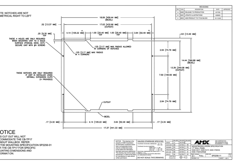
The DC19 panel PC is a rugged, fanless and maintenance-free human-machine interface
(HMI) for railway applications. It features a 10.4" display and touch screen or 32
illuminated front keys. Its small, ultra-flat mechanical design and configuration options
save space in the driver cabin and allow the panel to be tailored for all types of
applications in different train models. In addition, its full software compatibility with the
12.1" DC20 panel PC both increases flexibility and lowers costs, e.g., if an upgrade to a
larger panel is necessary.
High-Quality, High-Resolution Display
The DC19 houses a robust impact-resistant XGA TFT LCD display with LED backlight. It
also features LEDs and a light sensor at the front. Due to its high resolution and
optimized usability, it is a perfect choice for, e.g., CCTV.
Powerful & Energy-Efficient Computing
The DC19 is powered by an Intel Atom processor from the E3900 series running at up to
1.6 GHz and equipped with up to 8 GB RAM with ECC and a 32 GB soldered eMMC.
Standard interfaces include two Gigabit Ethernet, one CAN, one audio, digital I/O and
RS232/RS422/RS485 - all available on M12 connectors at the back of the panel PC.
Two PCI Express Mini Card interfaces can control wireless communication functions like
2G, 3G, 4G and GNSS. Two micro-SIM card slots with dual-SIM functionality are accessible
at the back of the panel.
Flexible Rail Network Connection Options
The DC19 can provide Multifunction Vehicle Bus (MVB) master or slave support where
necessary, by adding an MVB PCI Express Mini Card. This makes the display scalable for
different applications.
Extremely Rugged, Perfectly Rail-Ready
The DC19 comes with an extremely rugged housing with an IP65 compliant front. It
supports a railway-compliant power supply of 24 V DC to 110 V DC, its internal PSU
complying with EN 50155 class S2. Also in compliance with the standard, the DC19
operates in a -25 °C to +70 °C environment (+85 °C for 10 minutes), achieved through
fanless conduction-cooling technology.
All electronic components are soldered to withstand shock and vibration, backed up by
solid M12 connectors, and protected by conformal coating. Long-term availability until
2027 ensures an extended product life and future-safety. The panel PC meets all
important requirements for railway equipment for fast, competitive time-to-market even
in mission-critical environments.

Product Overview
20DC19-00 E1 2020-10-27 15
1.2.2 Functions
Figure 3. Functional diagram
Intel Atom Processor
E3900 Series
DDR3
SDRAM Gigabit Ethernet
Gigabit Ethernet
USB 2.0
Digital I/O
Audio in/out
CAN
PCIe Mini
Card Slot B B
2 micro-SIM
Slots B
Up to 2 antennas
R
R
R
R
R
R
RS232/RS422/RS485 R
RMVB
F
F
F
Power LED
Temperature LED
Warning LED
eMMC
32 GB B
PCIe Mini
Card Slot A B
R
FFront
Rear
R
B Onboard
Options
RUp to 2 antennas
Power Supply R

Product Overview
20DC19-00 E1 2020-10-27 16
1.3 Technical Data
CPU
The following CPU types are supported:
-Intel Atom x5-E3930, 2 cores, 2 threads, 1.3 GHz, 1.8 GHz Turbo Boost, 6.5 W,
2 MB cache
-Intel Atom x5-E3940, 4 cores, 4 threads, 1.6 GHz, 1.8 GHz Turbo Boost, 9.5 W,
2 MB cache
-Intel Atom x7-E3950, 4 cores, 4 threads, 1.6 GHz, 2.0 GHz Turbo Boost, 12 W,
2 MB cache
Display
Size/Resolution: 10.4" (4:3) / 1024 × 768
Color depth: 16.2 M
Luminance: 350 cd/m²
Viewing angle: 80° / 80° / 80° / 80° [r/l/u/d]
Memory
System RAM
-Soldered DDR3, ECC
-8 GB max.
Security
TPM (Trusted Platform Module 2.0)
Mass Storage
-eMMC (soldered); 32 GB
Wireless Functionality
Possible wireless functions:
-GNSS
-LTE
-WLAN
Interfaces
This product includes interface options
-Variable I/O in cutouts
Touch screen
-Touch technology: PCAP
-Touch mode: Multi-touch (2 points)
Key interface
-Number of keys: 32
Light sensor
-Light sensor position: top left

Product Overview
20DC19-00 E1 2020-10-27 17
Audio
-1x M12, A-coded, receptacle
-Stereo line input, single-ended
-Stereo line output, differential
USB
-1x USB 2.0, M12, A-coded, receptacle
Ethernet
-2x 10/100/1000BASE-T, M12, X-coded, receptacle
PCI Express Mini Card
-2x PCI Express Mini Card slot
-PCIe Full-Mini; PCIe x1, USB 2.0
SIM card
-2x micro-SIM card slot, externally accessible
Digital I/O
-2x digital input, isolated, M12, B-coded, receptacle
-2x digital output, isolated, M12, B-coded, receptacle
Serial
-1x RS232/RS422/RS485, isolated, M12, A-coded, receptacle
CAN bus
-1x CAN isolated, M12, A-coded, receptacle
LED
-Status: power status, system status
-User configurable: 1x
Cutout
-Antenna connector options: RP-SMA plug, RP-SMA receptacle, SMA plug, SMA
receptacle
-D-Sub options: MVB
Power
-1x power in, M12, A-coded, plug
Earthing connection:
-M4 stud
Supervision and Control
Temperature measurement
Board management controller
Real-time clock, buffered by supercapacitor (3 days)
Electrical Specifications
Supply Voltage: 24 V DC to 110 V DC nom. (EN 50155)
Power consumption: 30 W

Product Overview
20DC19-00 E1 2020-10-27 18
Mechanical Specifications
Dimensions:
-(W) 310 mm, (D) 214 mm, (H) 75 mm
-Cutout: (W) 280 mm, (H) 205 mm
Weight: 4.5 kg
Cooling: Air cooling, natural convection, airflow 0.4 m/s
Protection rating: IP65 (front), IP20 (back and sides)
Product Compliance: Rail - Rolling Stock
Operating temperature: -25 °C to +70 °C, +85 °C for 10 min (EN 50155:2017, class
OT3, ST1)
Rapid temperature variations: EN 50155:2017, class H1, no requirements
Storage temperature: -40 °C (EN 50155:2017) to +85 °C (EN 60068-2-2, Bb)
Altitude: +3000 m max. (EN 50125-1:2014, class AX)
Pollution degree: EN 50124-1:2017, class PD2
Humidity: +55 °C and +25 °C, 100 % RH max. (EN 50155:2017)
Shock: 30 ms @ 50 m/s² (EN 61373:2010/AC:2017-09, vehicle body, cat. 1, class B)
Vibration: 10 min @ 2.02 m/s² (functional) and 5 h @ 11.44 m/s² (long-life) (EN
61373:2010/AC:2017-09, vehicle body, cat. 1, class B x 2)
Power supply
-Interruption of voltage supply: 10 ms (EN 50155:2017, class S2)
Electrical safety
-EN 50124-1:2017
-EN 50153:2014 + A1:2017
-EN 50155:2017
-EN ISO 13732-1:2008
Fire protection: EN 45545-2:2013 + A1:2015, HL3
EMC emission
-EN 50121-3-2:2016
-Regelung Nr. EMV 06 :2014-07-29, Anhang E: Messung an Geräten
-Regelwerk 50.02.01 :2016-12-01, 12.3.1. EMV - Funk
EMC immunity: EN 50121-3-2:2016
Protective coatings: EN 50155:2017, class PCX (As agreed between user and
supplier)
Useful life: 5 years (EN 50155:2017, class L1)
Display compliance: UIC 612-01
Reliability
MTBF: 50 000 h predicted @ 40 °C according to IEC/TR 62380 (RDF 2000)
See the duagon website for technical product drawings including the
exact dimensions of DC19:
www.duagon.com/products/dc19/#doc

Product Overview
20DC19-00 E1 2020-10-27 19
BIOS/Boot Loader
AMI Aptio UEFI Firmware
Software Support
Linux
-Supported kernel: 4.8 or higher. For older kernels (e.g., 4.4.x), patches for the
Intel Atom Processor E3900 Series platform are also available.
-Driver support
-Tool support
Windows
-Windows 10 IoT Enterprise 64-bit
-Driver support
-Tool support
-Not all functions are supported
1.4 Cooling Concept
The DC19 is cooled by natural convection for fanless operation.
See Chapter 2.6 Using the DC19 under Linux on page 30.
See Chapter 2.7 Using the DC19 under Windows on page 37.
See section Software on the product web page for available packages:
www.duagon.com/products/dc19/#downl
See also Application Note Recommendations for a Robust Software
Setup
Leave the following minimum space to those sides of the system that are
needed for cooling to enable the required airflow:
15 cm
The following sides are needed for cooling:
top
bottom
front
left
right

Product Overview
20DC19-00 E1 2020-10-27 20
1.5 Product Identification
The documentation may describe several different models and design revisions of the
DC19. You can find the article number, design revision and serial number on either the
product label or the system label.
Article number: Indicates the product family and model. This is also the main
ordering number. To be complete it must have 9 characters.
Revision number: Indicates the design revision of the product.
Serial number: Unique identification assigned during production.
If you need support, you should communicate these numbers to us.
Figure 4. Product label
Article No.:
01AXXX-00
Serial No.:
000001
Rev.: 00.00.00
Revision numberSerial number
Complete article number
Table of contents


