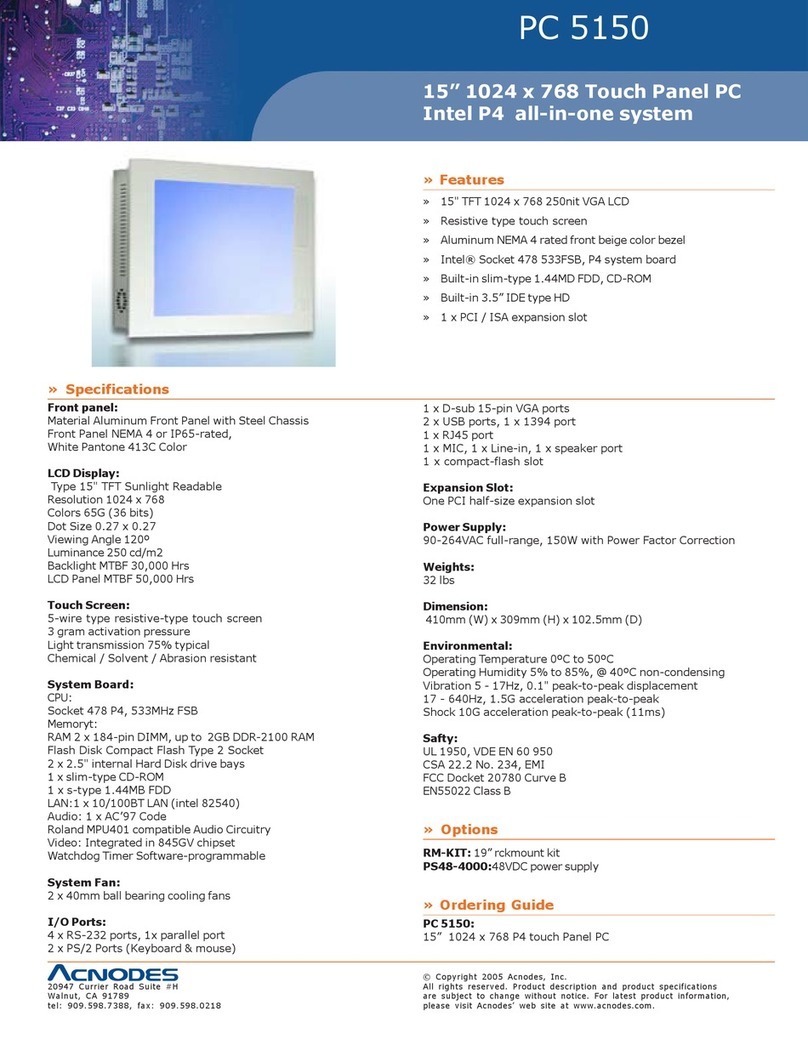
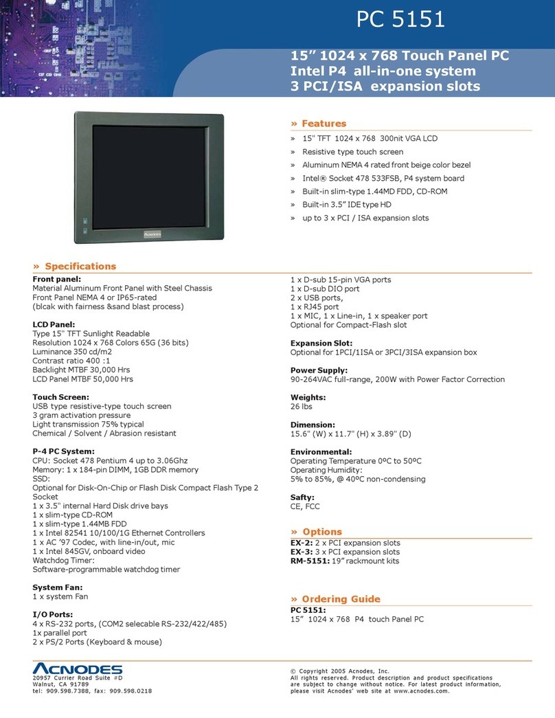
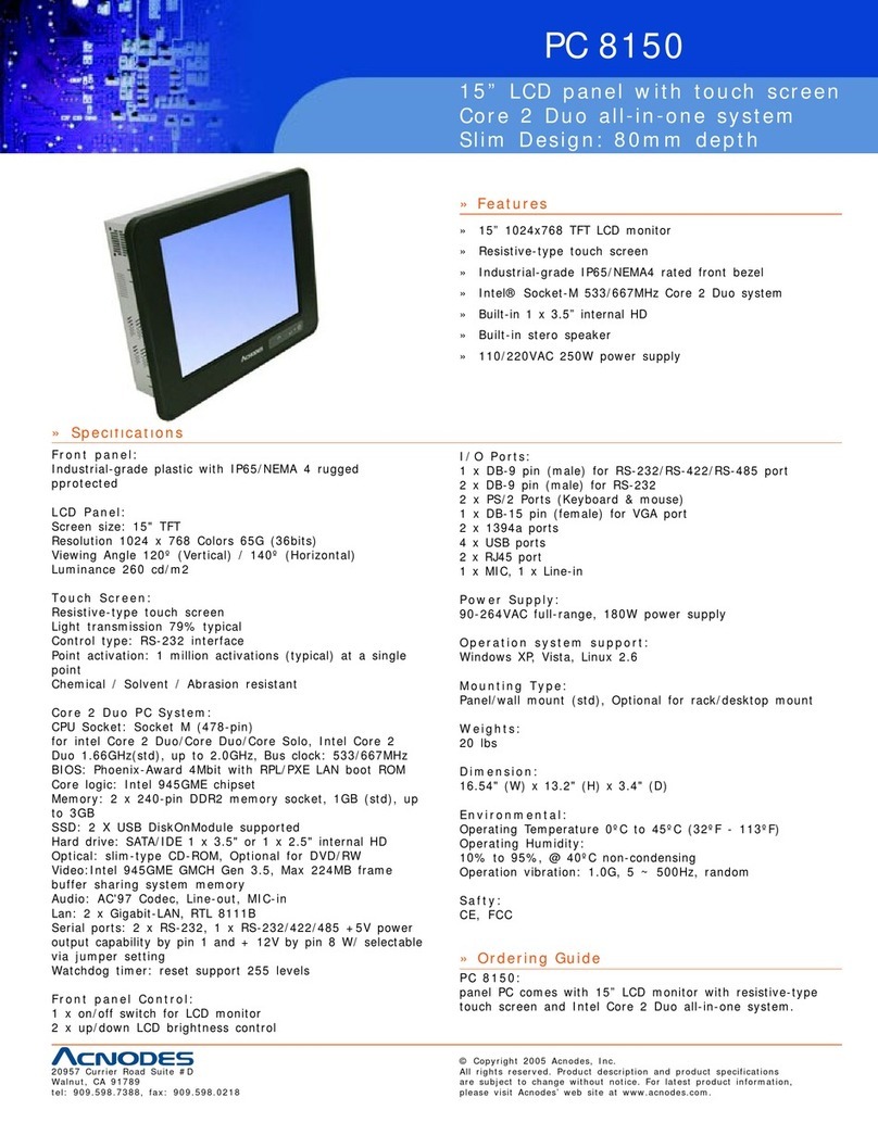
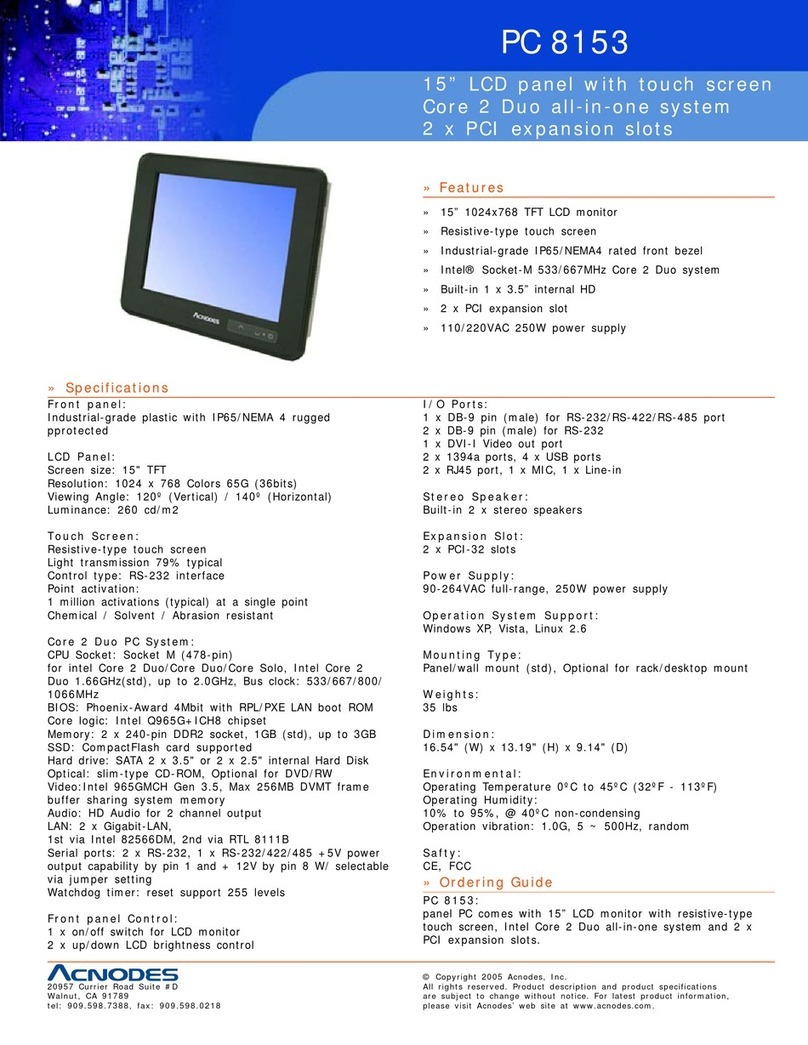
Acnodes PCM8011 User manual

User Manual
Embedded Computers
PCM8011
10.4" Military-Grade Panel PC
In
tel Celeron N2930 1.83GHz CPU
MIL-STD-461F / 810G Testing Compliance
All rights reserved. Product description and product specifications are subject to change without notice.
For latest product information, please visit Acnodes’ website at www.acnodes.com.
14628 Central Ave. Chino, CA 91710 Tel: 909.597.7588
Fax: 909.597.1939
© Copyright 2021 Acnodes Corp.

2
CHAPTER 1
Declaration
Please read this chapter with some important notice before operations.

3
FCC Regulation Statement
This device complies with part 15 FCC rules.
Operation is subject to the following two conditions:
• This device may not cause harmful interference.
• This device must accept any interference received including interference that may cause
undesired operation.
This equipment has been tested and found to comply with the limits for a class “a”
digital device, pursuant to part 15 of the FCC rules. These limits are designed to provide
reasonable protection against harmful interference when the equipment is operated in a
commercial environment. This equipment generates, uses, and can radiate radio frequency
energy and, if not installed and used in accordance with the instruction manual, may
cause harmful interference to radio communications. Operation of this equipment in a
residential area is likely to cause harmful interference in which case the user will be required to
correct the interference at him own expense.
Copyright Notice
No part of this document may be reproduced, copied, translated, or transmitted in any form or
by any means, electronic or mechanical, for any purpose, without the prior written
permission of the original manufacturer.
Disclaimer
We reserves the right to make changes, without notice, to any product, including circuits and/or
software described or contained in this manual in order to improve design and/or performance.
We assume no responsibility or liability for the use of the described product(s), conveys no
license or title under any patent, copyright, or masks work rights to these products, and makes
no representations or warranties that these products are free from patent, copyright, or mask
work right infringement, unless otherwise specified. Applications that are described in
this manual are for illustration purposes only. We make no representation or warranty that
such application will be suitable for the specified use without further testing or modification.

4
Warranty
Our warranty that each of its products will be free from material and workmanship defects for a
period of one year from the invoice date. If the customer discovers a defect, we will, at its
option, repair or replace the defective product at no charge to the customer, provided it is
returned during the warranty period of one year, with transportation charges prepaid. The
returned product must be properly packaged in it’s original packaging to obtain warranty
service.
Customer Service
The user guide includes simple debug and trouble shooting. For system crack or serious
damage, please contact with your distributor, sales representative, or the customer service
center for technical support if you need additional assistance. You may have the following
information ready before you call:
Product serial number
Peripheral attachments
Description of complete problem
The exact wording of any error messages
Warranty

CAUTION
Read manual prior to installing the product. The operation of products depends on your
reading and following the information in this manual. Re-check your work prior to
operating the product.
EVENT
EFFECT
PREVENTION
Although the brightness is
good under sunlight, it
shines directly all day would
cause the panel damage.
You should avoid exposing
the computer under the
sunlight for whole working
hours.
If the product is close to
explosive environment or
such as on fire, the
overheat will cause the
product malfunction.
You should avoid placing
the product near explosive
or firing environment.
If the product is close to
the wet ground such as
grassplot, the moisture
between panel and glass
will make the product
malfunction.
You should avoid placing
the product on the ground.
5
Safety Instructions
Always completely disconnect the power cord from your chassis whenever you work
with the hardware. Do not make connections while the power is on. Sensitive
electronic components can be damaged by sudden power surges. Only experienced
electronics personnel should open the PC chassis.

6
Safety Instructions
Always ground yourself to remove any static charge before touching the CPU card. Modern
electronic devices are very sensitive to static electric charges. As a safety precaution, use a
grounding wrist strap at all times. Place all electronic components in a static-dissipative surface or
static-shielded bag when they are not in the chassis.
Please read these safety instructions carefully.
• Please keep this user’s manual for later reference.
• Please disconnect this equipment from any AC outlet before cleaning. Do not
use acid or caustic liquid or spray detergents for cleaning. The good option is to use a damp cloth.
• Do not touch the LCD panel surface with sharp or hard objects.
• For pluggable equipment, the power outlet must be installed near the equipment and must be
easily accessible.
• Place this equipment on a reliable surface during installation. Dropping it or letting it fall could
cause damage..
• Make sure the voltage of the power source is correct before connecting the equipment to the
power outlet.
• Position the power cord so that people cannot step on it. Do not place anything over the power
cord.
• All cautions and warnings on the equipment should be noted.
• If the equipment is not used for a long time, disconnect it from the power source to avoid
damage by transient over-voltage.
• Never open the equipment. For safety reasons, only qualified service personnel
should open the equipment.

Getting Started
The design allows you to use it in radical industrial environments – places
you would not take with normal commercial grade LCDs / Panel PCs. The
mechanical is designed to be embedded in various kind of equipment.
This chapter tells you will find instructions for the following procedures:
• Introduction
• Unpacking
• Installing the monitor
7
CHAPTER 2

8
2-1 Specification
Display
Size 10.4”
Active Display Area 211.2(H) x 158.4(V)
Pixel Pitch (mm) 0.264(H) x 0.264(V)
Display Colors
Resolution 1024 x 768
Brightness 350 nits (Default; 1,000-nits for optional)
Contrast Ratio 1,000:1 (typ.)
Viewing Angle 88/88/88/88 (L/R/U/D)
System
Processor Intel® Celeron® Bay Trail-M N2930 1.83GHz
System Memory 4GB DDR3L 1066/1333 SODIMM
System Chipset Intel® ATOM® SoC integrated
Storage Built-in 64GB mSATA SSD
Ethernet Dual Intel WG82574L GbE LAN
Touch 5-wire resistive touch screen (Default)
EMI Shield EMI Mesh filter applied
Power DC 9~36V with power isolation & surge protection
Operating System
Optional OS Windows 10 IoT Enterprise, Linux Support
Input/ Output (D38999 connector)
Serial Ports 1 x RS232 (D38999)
USB Ports 2x USB 2.0 (D38999)
1 x USB 2.0 (USB Type A receptacle)
Ethernet 1 x Gigabit LAN
Physical Buttons 1 x Power Button
1 x Reset Button
Mechanical Specification
Cooling System
Mounting
Dimensions
Fanless design
Wall mount/ VESA mount
300.0 x 248.0 x 77.0 (WxHxD)
16.2M
Operating Temperature
Operating Humidity
IP Rating
-20 to +60°C
5%~95% at 40°C (non-condensing, RH)
Full-IP67
Environmental Considerations
Power Input
Power Cord
9~36V DC Input
N/A
Power Specifications

9
2-2 I/O Layout
1. 2. 3.
No Connector No Description
1
D38999/24A98BN P1 DC Power Input
2 D38999/24WB35PN P2 2x USB,1x RS232, 1x LAN
3 D38999/USBFTV71G P3 USB2.0 TypeA Receptacle

10
2-3 OSD Keypad
2-4 Pin Definition
Power On/Off
Power LED Indicator
Storage LED Indicator
Reset Button
Pin# Pin Definition
AD+
BD-
C GND
1. Power Connector (D38999/24WA98PN)
2. Signal Connector (D38999/24WD35PN)
USB
RS232
LAN
Pin# Pin Definition Interface
14 TX_D1+
15 TX_D1-
16 RX_D2+
17 RX_D2-
18 BI_D3+
28 BI_D3-
29 BI_D4+
30 BI_D4-
Pin# Pin Definition Interface
27 CD
12 RXD
13 TXD
26 DTR
33 GND
34 DSR
35 RTS
36 CTS
37 RI
Pin# Pin Definition Interface
8 USB1_VCC
9 USB1_GND
10 USB1_D-
11 USB1_D+
22 USB2_VCC
23 USB2_GND
24 USB2_D-
25 USB2_D+
LAN1
USB
RS232

Operation
When using a device, be sure to read the instructions accompanying the
device together with the relevant section in this chapter. This chapter gives
guidelines on using the device
11
CHAPTER 3

12
3-1 Mounting
3-1-1 VESA Mount
There are 75x75, 100x100 VESA threads at back for wall mount or VESA pole mount.
3-1-2 Panel Mount (By request)
There are 4 x M4 threads on the right /left side of terminal if panel mount is needed.

13
3-2-2 Power-On the system
After power has been correctly connected, try to power on the unit by pressing the power
button in front. Without pre-installed OS, power indicator will be light with green color, and
system will ask for a booting device. For the booting device, please check chapter 4 in BIOS
settings. With pre-installed OS, system will automatically run with OS initialized procedure.
3-2 Connection
First of all, please make the power cable according to the Pin table (on Chapter 2-4). One end
(D38999/24WA98SN) to the terminal, another end to the DC power source. DC Input could be
9~36V @40wattage*.
*Wattage will be subject to change with different spec., please double check with your sales
representative for correct electric current.
3-2-1 Cable connection

14
BIOS Setup
CHAPTER 4
BIOS Setup Utility is a program for configuration basic Input /
Output system settings of the HMI for optimum use. This
chapter provides information on how to use BIOS setup, its
functions and menu

15
4-1 BIOS Setup
BIOS Setup
This chapter provides information on how to use BIOS setup, its functions and menu.
When and How to Use BIOS Setup
To enter the BIOS setup, need to connect an external USB keyboard, press <Del> key when
the prompt appears on the screen during start up. The prompt screen shows only few seconds,
press <Del> key quickly. If the message disappears before your respond, restart the system by
turning it OFF and ON, and enter the BIOS again.
Run BIOS setup utility for:
1. Error message on screen indicates to check BIOS setup
2. Restoring the factory default settings.
3. Modifying the specific hardware specifications
4. Necessity to optimize specifications
4-2 BIOS Functions
BIOS Navigation Keys
BIOS navigation keys for keyboard control are listed
below. The following keys are enabled during POST:
Key
Function
Del
Enters the BIOS setup menu.
F7
Display
the boot menu. Lists all bootable devices that
are
connected
to the system. With cursor ↑and cursor ↓and
by
pressing
<ENTER>, select the device used for the boot.
Pause
Pressing the [Pause] key stops the POST. Press any other key to
resume the POST.

16
The following Keys can be used after entering the BIOS Setup.
Key
Function
F1
General Help
F2
Previous Values
F3
Optimized Defaults
F4
Save & Exit
Esc
Exit
+/
-
Change Opt.
Enter
Select or execute command
Cursor ↑
Moves to the previous item
Cursor ↓
Goes to the next item
Cursor ←
Moves to the previous item
Cursor →
Goes to the next item
BIOS Main Menu
When you enter BIOS setup, the first menu that appears on the screen is the main menu. It
contains the system information including BIOS version, processor RC version, system language,
time, and date.
Immediately after the [DEL] key is pressed during startup, the main BIOS setup menu appears:

17
BIOS
Setting
Description Setting Option Effect
System
Language
Displays the system
language. [English] is
set up by default.
Adjustment of the
language
Set the language in
other language. The
language in this
device is English.
System
Date/Time
This is current date
setting. The time is
maintained by the
battery when the
device is turned off.
Date and time
changes.
Set the date in the
format [mm/
dd/yyyy];
The time in the format:
[
hh/mm/ss]
Access Level
The current user
access settings
Changes to the level
of access
Administrator is set up
by the default
Advanced Menu
The advanced menu also uses to set configuration of the CPU and other system devices. There
are sub menus on the left frame of the screen.
For items marked ► press <Enter> for more options.
Advanced Configuration and Power Interface (ACPI) settings allow to control how the power
switch operates. The power supply can be adjusted for power requirements. You can use the
screen to select options of ACPI configuration. A description of the selected items will appear
on the right side of the screen.

18
BIOS Setting
Description
Setting Option
Effect
ACPI Settings
Configures ACPI settings
Enter
Opens
submenu
F81866 Super IO
Configuration
Configures IO settings
Enter
Opens
submenu
Hardware Monitor
Configures Hardware Monitor
settings
Enter
Opens
submenu
S5 RTC Wake Settings
Configures RTC Wake
parameters
Enter
Opens
submenu
CPU Configuration
Configures CPU settings
Enter
Opens
submenu
PPM Configuration
Configures PPM settings
Enter
Opens
submenu
Thermal Configuration
Configures Thermal
Parameters
Enter
Opens
submenu
IDE Configuration
Configures IDE Parameters
Enter
Opens
submenu
Miscellaneous
Configuration
Configures Miscellaneous
Parameters
Enter
Opens
submenu
CSM Configuration
Configures CSM Parameters
Enter
Opens
submenu
USB Configuration
Configures USB Settings
Enter
Opens
submenu
Platform Trust
Technology
Configures Platform Trust
Technology parameters
Enter
Opens
submenu
Security Configuration
Configures Security
parameters
Enter
Opens
submenu
For items marked ► press <Enter> for more options.

19
Advance Menu -> ACPI Settings
Advanced Configuration and Power Interface (ACPI) settings allow to control how the power
switch operates. The power supply can be adjusted for power requirements.
You can use the screen to select options of ACPI configuration. A description of the selected
items will appear on the right side of the screen.
BIOS Setting
Description
Setting Option
Effect
Enable ACPI Auto
Configuration
BIOS ACPI Auto
Configuration
Enable/
Disable
Enables or Disables this
function
Enable Hibernation
Control
hibernation
Enable/
Disable
Enables or Disables this
function

20
Advance Menu -> F81866 Super IO Configuration
You can use the screen to select options for Super IO Configuration, and change the value of
the option selected. A description of the selected item appears on the right side of the screen.
For items marked with ►, please press <Enter> for more options.
Serial Port 1~5
Use these items to set parameters related to serial port 1~5.
Watch Dog Time Select
You can either disable Watch Dog Time Select, or set up the time.Use <Arrow> keys to
navigate and please press <Enter> to select the item
Table of contents
Other Acnodes Touch Panel manuals

Acnodes
Acnodes PC 8150 User manual

Acnodes
Acnodes PC 5152 User manual

Acnodes
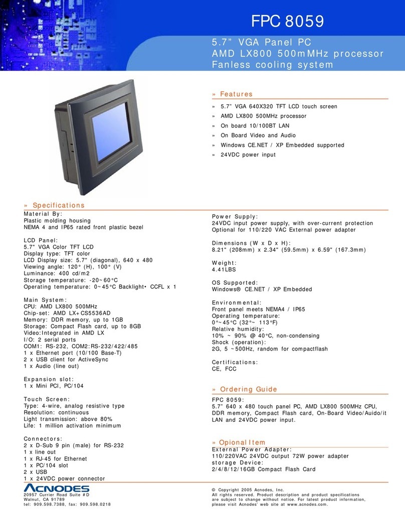
Acnodes FPC 8059 User manual

Acnodes
Acnodes PCH3782 User manual

Acnodes
Acnodes PC 2120 User manual

Acnodes
Acnodes PC 8153 User manual

Acnodes
Acnodes PC 5171 User manual

Acnodes
Acnodes PC 1150 User manual

Acnodes
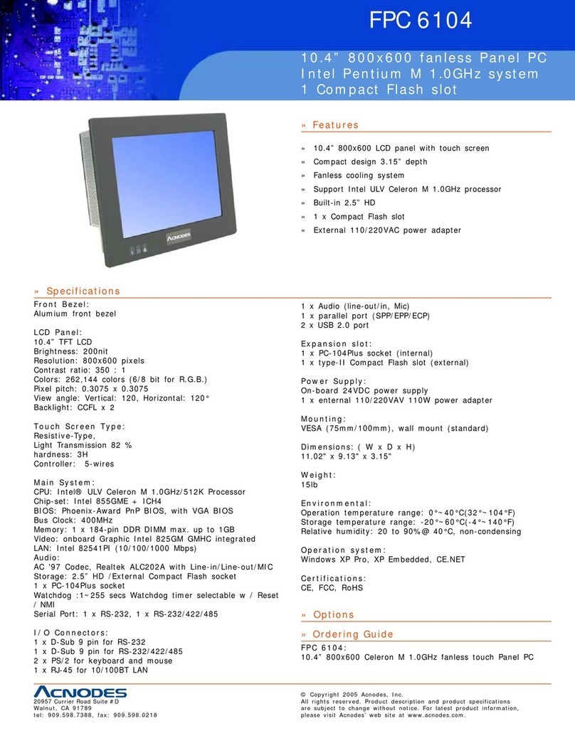
Acnodes FPC 6104 User manual

Acnodes
Acnodes PC8719 User manual

Acnodes
Acnodes PC 5152 User manual

Acnodes
Acnodes PC 5192 User manual

Acnodes
Acnodes FPC 8104 User manual

Acnodes
Acnodes FOX 9981 User manual

Acnodes
Acnodes PC 5151 User manual

Acnodes
Acnodes PC 1060 User manual

Acnodes
Acnodes PC 8120 User manual

Acnodes
Acnodes PC 1150 User manual

Acnodes
Acnodes PC 6150 User manual

Acnodes
Acnodes PC 5170 User manual