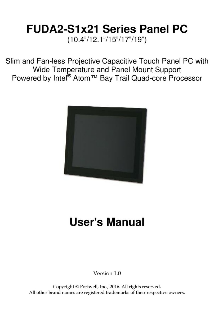
Portwell FUDA3-S1-22 Series User manual

FUDA3-S1x22 Series Panel PC
(10.4”/12.1”/15”)
Slim and Fan-less Projective Capacitive Touch Panel PC
Powered by Intel® Atom™ x7-E3950 Quad-core Processor
User's Manual
Version 1.0
Copyright © Portwell, Inc., 2016. All rights reserved.
All other brand na es are registered trade arks of their respective owners.

Preface
Table of Contents
How to Use This Manual
Chapter 1 System Overview...................................................................................................................... 1-1
1.1 Introduction ..................................................................................................................................... 1-1
1.2 Check List ....................................................................................................................................... 1-3
1.3 Product Specification ...................................................................................................................... 1-5
1.4 Mechanical Dimension.................................................................................................................... 1-6
1.5 Safety Instruction ............................................................................................................................ 1-9
1.5.1 Electrostatic Discharge (ESD)............................................................................................. 1-10
1.5.2 Grounding Method .............................................................................................................. 1-10
1.5.3 Instructions for the Lithium Battery...................................................................................... 1-11
1.5.4 FCC Statement ................................................................................................................... 1-11
1.5.5 Electromagnetic Compatibility............................................................................................. 1-11
Chapter 2 System Installation................................................................................................................... 2-1
2.1 Embedded Board H/W Jumper Setting Introduction ....................................................................... 2-1
2.1.1 Main Board ........................................................................................................................... 2-1
2.1.2 Extension Board.................................................................................................................... 2-7
2.2 I/O Extension Kit Installation ........................................................................................................... 2-9
2.3 Memory Module Installation .......................................................................................................... 2-11
2.4 HDD/SSD Storage Installation ...................................................................................................... 2-12
2.5 Half size Mini-PCIe WiFi/BT Module Installation ........................................................................... 2-13
2.6 Half size Mini-mSATA Module Installation .................................................................................... 2-15
2.7 Getting Started.............................................................................................................................. 2-16
2.8 I/O Interfaces ................................................................................................................................ 2-17
2.8.1 Front View........................................................................................................................... 2-17
2.8.2 Rear View ........................................................................................................................... 2-18
2.8.3 Top View............................................................................................................................. 2-20
2.8.4 Side View............................................................................................................................ 2-20
2.9 Mounting Method .......................................................................................................................... 2-20
2.9.1 Panel Mount........................................................................................................................ 2-20
2.9.2 VESA®Mount...................................................................................................................... 2-22
Chapter 3 Driver Installation, Touch Usage and PET introduction........................................................ 3-1
3.1 How to Get the Driver...................................................................................................................... 3-1
3.2 Driver Installation ............................................................................................................................ 3-2
3.2.1 Intel® Chipset Driver Installation........................................................................................... 3-2
3.2.2 Intel® HD Graphics Driver Installation .................................................................................. 3-3
3.2.3 Intel® I210 Gigabit Ethernet Controller Driver Installation..................................................... 3-5
3.2.4 Intel® Trust Execution Engine Driver Installation.................................................................. 3-7
3.2.5 Intel® Serial IO Driver Installation......................................................................................... 3-9
3.2.6 Nuvoton Super I/O High-Speed Driver Installation.............................................................. 3-11
3.2.7 WiFi and Bluetooth Driver Installation ................................................................................. 3-13
3.3 Windows 10 Gesture for Multi-Touch Demand ............................................................................. 3-17
3.4 Portwell Software Service ............................................................................................................. 3-18
Chapter 4 BIOS Setup Information ........................................................................................................... 4-1
4.1 Entering Setup—Launch System Setup.......................................................................................... 4-1
4.2 Main ................................................................................................................................................ 4-2
4.3 Configuration................................................................................................................................... 4-3
4.4 Security......................................................................................................................................... 4-30
4.5 Boot............................................................................................................................................... 4-31
4.6 Save and Exit................................................................................................................................ 4-34
Chapter 5 Important Instructions.............................................................................................................. 5-1
5.1 Note on the Warranty...................................................................................................................... 5-1
5.2 Exclusion of Accident Liability Obligation........................................................................................ 5-1
5.3 Liability Limitations / Exemption from the Warranty Obligation ....................................................... 5-1
5.4 Declaration of Conformity................................................................................................................ 5-1
Chapter 6 Frequent Asked Questions ...................................................................................................... 6-2
Preface
How to Use This Manual
The anual describes how to configure your FUDA3-S1x22 Series Panel PC syste to
eet various operating require ents. It is divided into four chapters, with each
chapter addressing a basic concept and operation of Fan-less Panel PC Syste .
Chapter 1: System Overview. Present what you have in the box and give you an
overview of the product specifications and basic architecture for Panel PC syste .
Chapter 2: System Installation. Show the definitions and locations of all the
interfaces and describe a proper installation guide so that you can easily configure
your syste .
Chapter 3: Driver Installation and Touch Usage Guide. Describe the operation
guide for included driver and software.
Chapter 4: BIOS Setup Information. Specify the eaning of each setup para eters,
how to get advanced BIOS perfor ance and update new BIOS. In addition, POST
checkpoint list will give users so e guidelines of trouble-shooting.
Chapter 5: Important Instructions. Indicate so e instructions which ust be
carefully followed when the Panel PC syste is used.
Chapter 6: Frequent Asked Questions. Provide the answers for the ost frequently
asked questions.
The content of this anual is subject to change without prior notice. These changes
will be incorporated in new editions of the docu ent. The vendor ay ake
supple ent or change in the products described in this docu ent at any ti e.
Portwell, Inc. clearly infor s the users that this anual only encloses a general
description of technical processes and instructions which ay not be applicable in
every single case. In cases of doubt, please contact Portwell, Inc.
© 2022 Portwell, Inc. All Rights Reserved.
Portwell, Inc.
http://www.portwell.co .tw
Address : No. 242, Bo-Ai Street, Shu-Lin District, New Taipei City, 238, Taiwan
TEL:+886-2-7731-8888 ; FAX:+886-2-7731-9888

Preface
Revision History
Revision
Date Details of Change(s)
V1.0 2022/6/20 Initial Release

System Overview
FUDA3-S1x22 Series Panel PC User’s Manual 1-1
Chapter 1
System Overview
1.1 Introduction
Powered by Intel® Ato ™ E3950, which provides extended te perature and
flexible I/O connectivity within 12 Watt ther al design power (TDP), FUDA3 Series
Panel PC is an ideal platfor for applications like highly efficient and dedicated
i age signal processing with secure content delivery and visually appealing HMI
thin clients.
Equipped with a high resolution panel and a sleek, responsive, ulti-touch screen,
FUDA3 Multi-Touch Panel PC co es with an IP65 rated front bezel and true-flat
design. This allows the syste to be operated in harsh environ ent. With its refined
appearance, rugged echanical chassis and ultiple odular flexibility, FUDA3
Series Panel PC's application-oriented design provides custo ers an ideal HMI
solution for factory auto ation applications.
Thanks to its robustness and easy operation, Panel PC with projective capacitive
touch screen beco es a popular solution in the factory auto ation industry. With the
latest touch screen technology, FUDA3 Multi-Touch Panel PC Series is responsive
even when thick industrial gloves are worn and supports pal rejection. Moisture,
conta inant, and cutting oil are co on in an industrial environ ent, so it is
i portant these aterials don’t cause any false actions to the achine. Last but not
least, its excellent noise i unity akes it suitable in industrial application.
New touch technologies, such as excellent noise i unity for any Industrial
environ ent (CS 10Vr ), excellent radiated susceptibility support up to 50V/ ,
pre iu water resistance perfor ance and heavy glove support, are i ple ented
on FUDA3 Multi-Touch screen series Panel PC. It can solve the proble that
projective capacitive ulti-touch screens do not operate effectively within an
industrial input voltage noise interference environ ent. We believe, “that adopting
our FUDA3 Series Panel PC is the obvious choice to adopt in industrial HMI arket.”
As we all know, UART port such as RS-232/422/485 is very i portant I/O to
co unicate between device and device at factory. FUDA3 Panel PC adopt new
Super I/O chip to ake UART ports support high-speed baud rate fro 115.2K up to
axi u 921.6K under Windows 10. The advantage can solve I/O co unication
slowly proble in factory auto ation environ ent and i ple ent High-speed
UARTs Support

System Overview
FUDA3-S1x22 Series Panel PC User’s Manual 1-2
FUDA3 Series Panel PC features all required interfaces for industrial application:
12V ~ 24V DC input, dual LAN, ultiple USB ports and RS-232/422/485 selectable in
BIOS with auto-flow function. Different I/O extension kits can be chosen to serve
different arket de and.

System Overview
FUDA3-S1x22 Series Panel PC User’s Manual 1-3
1.2 Check List
The FUDA3-S1x22 Series Panel PC package covers the following ite s:
Essential
One FUDA3-S1x22 Panel PC
Panel Size Model Name
10.4” FUDA3-S1022
12.1” FUDA3-S1222
15” FUDA3-S1522
Screws for HDD installation
M3X4L Screw 4 pieces
3-pin Ter inal Block Connector (Fe ale)
Optional
Panel Mount Kits
Panel Size Kits (pcs)
10.4” 8 pieces
12.1” 8 pieces
15” 14 pieces
17” 16 pieces
19” 20 pieces
60W Power Adapter with Power Cord (EU/US type) and Switch Cable
60W P wer Adapter
P wer C rd (US type)
P wer C rd (EU type)
P wer Switch Cable (fr m DC Jack t 3-pin TBC)
I/O Extension Kit for FUDA2-S1022
2x RS-232/422/485
(Expansi n: Opti n 0)

System Overview
FUDA3-S1x22 Series Panel PC User’s Manual 1-4
I/O Extension Kit for FUDA3-S1222/1522
2x RS-232/422/485, 2x USB 2.0
(Expansi n: Opti n 0)
2x RS-232/422/485, 1x RS-232
(Expansi n: Opti n 1)
If any of these ite s is da aged or issing, please contact your vendor and keep all
packing aterials for future replace ent and aintenance.

System Overview
FUDA3-S1x22 Series Panel PC User’s Manual 1-5
1.3 Product Specification
Model Name
FUDA
3
-
S10
2
2
FUDA
3
-
S12
2
2
FUDA2
-
S15
2
2
Display
L
CD Size
10.4”
12.1"
15”
N
/A
N
/A
Resolution
XGA 1024 x 768
XGA 1024 x 768
XGA 1024 x 768
N
/A
N
/A
rightness
450 cd/m
2
6
00 cd/m
2
450 cd/m
2
N
/A
N
/A
Contrast Ratio
3000:1
700:1
700:1
N
/A
N
/A
acklig
ht
LED type
LED type
LED type
N
/A
N
/A
Touch Window
P
oj
ective Capacitive Multi
-
Touch
(10 points)
System
SOC
Intel
®
Atom™
x7
-
E3950
(
Quad
Co e
1
.6
G
Hz
, 2M Ca
che,
up
2
.0
GHz)
Memory
DDR3L S
O
-
DIMM
1866
MHz max up to 8
GB
IOS
AMI
Graphics
Intel®
HD
Gen
9
G aphics
LVDS
Single/Dual Channel 24
-
bit
LAN Chipset
Dual Intel
®
I
Gigabit Ethe net
Chi
pset
Aud
io
N/A
Watchdog Timer
P og ammable
1~255
secs
Storage Device
2.5" SATA HDD / SSD,
Min
i
-
mS
ATA
OS
Windows 10 /
Linux™
I/O Interface
Series Port
2
x RS
-
232/422/485 (
Expansion
:
Option 0
)
Display
1 x
H
DMI
US
1 x
USB OTG,
2
x
USB 3.0
1 x USB OTG, 2 x USB 3.0, 2 x USB 2.0 (Expansion: Option 0)
Ethernet
2 x Gigabit Ethe net
Others
1 x SMA Antenna hole fo WiFi
/3G Solution
Expansion
1 x
Full
-
size
Mini
-
PCIe
socket
1 x Full-size Mini PCIe socket
1 x Half-size Mini PCIe/Mini-mSATA socket switch by jumpe
2 x RS-232/422/485, 1 x RS-232 (Expansion: Option 1)
1 x
Half
-
s
ize Mini
PCIe/Mini-mSATA
socket switch by
jumpe
Mechanical
Mounting (mm)
VESA Mount 75 x 75 & 100 x 100 ; Panel Mount
Weight (Kg)(N)
3.5 Kg
3.9
Kg
5.
1
Kg
N
/A
N
/A
Weight (Kg)(G)
5.8 Kg
6
Kg
7.8
Kg
N
/A
N
/A
Dimension
282
x 2
38
x 5
7.3
mm
305
x
260
x
58.
2
mm
384
x
310
x
56.
6
mm
N/A N/A
P
o
wer
Power
Supply
D
C12V
~
24V I
nput
wi
th 3
-
p
in
T
e minal
B
lock C
onnecto
Consumption (Max)
3
3.5
W (12V);
3
3
.6
W (24V)
40.9
W (12V);
3
9.4
W (24V)
40.5
W (12V);
40
.2
W (24V)
N/A N/A
Consumption (Min)
1
1.8
W (1
2V);
1
4
W (24V)
1
2
W (12V);
1
2.3
W (24V)
11.2
W (12V);
1
2
W (24V)
N/A N/A
Environmental
OP /Storage Temp
-
2
5
~
60
℃
/
-
40~85
℃
(20~90% non
-
c
ondensing)
Vibration
1.0G (
SSD
/Min
i
-
mSATA
) and 0.5G (HDD)
, Powe on & 2.16G, Packaged; 5~500Hz
, IEC 60068
-
2
-
6
Shock
15G peak accele ation, 11 ms (Powe on condition)
, IEC 60068
-
2
-
27
Drop
Package with Ca ton f om 96.5 cm (1
-
Co ne , 3
-
Axis, 6
-
Face)
, ISTA
2A Standa d
Front Panel
Protection
IP65 (F ont) / IP20 (Rea ), IEC 60529 Edition 2.1 Standa d
Certification
CE/FCC Class A
, UK
CA, EN
6236
8
-
1
, EN
61000
-
6
-
2, EN
61000
-
6
-
4

System Overview
FUDA3-S1x22 Series Panel PC User’s Manual 1-6
1.4 Mechanical Dimension
Front and side view of the FUDA3-S1022 syste
Back view of the FUDA3-S1022 syste

System Overview
FUDA3-S1x22 Series Panel PC User’s Manual 1-7
Front and side view of the FUDA3-S1222 syste
Back view of the FUDA3-S1222 syste

System Overview
FUDA3-S1x22 Series Panel PC User’s Manual 1-8
Front and side view of the FUDA3-S1522 syste

System Overview
FUDA3-S1x22 Series Panel PC User’s Manual 1-9
1.5 Safety Instruction
Caution:
This section should be carefully read and please abide by the instructions for
your own safety and correct use of the unit.
The chapter also includes infor ation on approval and interference inhibition of your
unit. Please abide by the warnings and instructions on the unit and in the anual.
The FUDA3-S1x22 Series Panel PC was built and tested by Portwell, Inc. in
accordance with and kept the co pany within under perfectly safe condition.
In order to retain this condition and ensure safe operation, the users ust abide by
the instructions and warnings
The unit ust be used in accordance with the instructions of usage.
The electrical installations in the roo ust not violate the require ents of the
local (country-specific) regulations.
Pay careful attention that there are no cables, especially power cables, in areas that
people can go over the .
Only use the power cord supplied as specification. Don’t use da aged power
cords.
Hints for DC power connection: The DC power source should be able to be switched
off and on via an isolating switch. The unit is only co pletely disconnected fro the
DC ain power source when the DC power cord is disconnected either fro the
power source or the unit. Therefore, the DC power cord and its connectors ust
always re ain within reach. The Power source should be SELV or fro the
secondary circuits are circuits where separation fro MAINS CIRCUITS is achieved
by a transfor er in which the pri ary windings are separated fro the secondary
windings by REINFORCED INSULATION, DOUBLE INSULATION, or a screen
connected to the PROTECTIVE CONDUCTOR TERMINAL
Hints for AC power connection via external AC/DC adapter: The ain power cable
of the optional external AC/DC adapter serves as disconnecting device. For this
reason the outlet of the AC power source ust be located near to the device and easy
to reach.
Never place the unit under direct sunlight, near heat sources or in a hu id place.
Make sure the unit has proper ventilation.
All plugs on the connection cables ust be screwed or locked to the housing.
FUDA3-S1x22 Series Panel PC is designed to be used on the desk or upright with
the I/O interfaces downwards.
The unit generates heat under operation condition. Make sure it is properly
ventilated. Never cover up the air intake and exhaust openings of the unit. Do not
i pede the fins of the heat sink.
Be aware of the war surface of heat sink at back side. A protective wear is
reco ended.

System Overview
FUDA3-S1x22 Series Panel PC User’s Manual 1-10
Repairs ay only be operated by specialists or technicians qualified and
authorized by Portwell, Inc.
Maintenance or repair on the open unit ay only be operated by specialists or
technicians qualified and authorized by Portwell, Inc. and fa iliar with the
related hazards.
When accessing internal co ponents, users ust switch off the unit and
disconnect it fro the power source.
Only original accessories (or suggested optional parts) approved and supplied by
Portwell, Inc. ay be used.
The installation that the safety of any syste incorporating the equip ent is the
responsibility of the asse bler of the syste .
If the equip ent is used in a anner not specified by the anufacturer, the
protection provided by the equip ent ay be i paired.
Assu ption of safe operation no longer possible ust be taken,
- if the unit has obvious da age or
- if the unit no longer functions.
Under such cases, the unit ust be shut down and secured against any
unintended operation.
1.5.1 Electrostatic Discharge (ESD)
A sudden discharge of electrostatic electricity can da age electrostatic-sensitive
devices or circuits. Adequate packaging and grounding techniques are essential to
avoid da age. Following precautions should be taken:
1. Deliver printed circuit boards in electrostatic-safe containers such as cartons,
boxes or anti-static bags.
2. Keep electrostatic-sensitive parts in their containers until they reach an
electrostatic-free station.
3. Follow adequate grounding when a sensitive PCB, co ponents, or asse blies are
touched.
4. Store electrostatic-sensitive PCB’s in a protective packaging or on conductive
foa .
1.5.2 Grounding Method
Protect against electrostatic da age of the unit by taking the following preventative
easures:
1. Cover workstations with approved anti-electrostatic aterial. Provide a wrist
strap connected to a working bench and properly grounded tools and equip ent.
2. For extra protection use anti-electrostatic ats, heel straps, or air ionizers.
3. Handle electrostatic-sensitive co ponents, PCBs, and asse blies with care
nearby the case or the edge of the board.
4. Prevent contact with pins, leads, or circuitry.
5. Switch off power and input signals before plugging and re oving connectors or
test equip ent.

System Overview
FUDA3-S1x22 Series Panel PC User’s Manual 1-11
6. Keep the work area free fro non-conductive aterials such as ordinary plastic
asse bly aids and Styrofoa .
7. Use field service tools with conductivity, such as screwdrivers, pliers, and
vacuu cleaners.
8. Always put drives and PCBs with the co ponent-side down on the working
bench.
1.5.3 Instructions for the Lithium Battery
Caution:
Please contact. Portwell, Inc directly. Prohibit replace by user
Do not throw away used CMOS batteries to do estic waste. Throw away the
battery according to the local regulations pertaining to the disposal of these
special aterials (e. g. to the collecting points for disposal of batteries).
1.5.4 FCC Statement
This equip ent has been tested and found to co ply with the li its for a Class A
digital device, pursuant to Part 15B of the FCC Rules. These li its are designed to
provide reasonable protection fro har ful interference when the equip ent is
operated in a co ercial environ ent. This equip ent generates, uses, and can
radiate radio frequency energy and, if not installed and used in accordance with the
instruction anual, ay cause har ful interference to radio co unications.
Operation of this equip ent in residential areas is likely to cause har ful
interference in which case the users will be required to correct the interference at
his/her own expense.
1.5.5 Electromagnetic Compatibility
The syste has been designed for industrial use. The ost recent version of the EMC
guidelines (EMC Directive 2014/30/EU) is applied following standards, EN 55011/
EN 61000-6-4 / EN 61000-6-2 and EN 55032 / EN 55035. If users odify and/or add
device to the equip ent (e.g. installation of add-on cards), the prerequisite for the CE
confor ity declaration (safety require ent) ay not be applicable any ore.

System Installation
FUDA3-S1x22 Series Panel PC User’s Manual 2-1
Chapter 2
System Installation
This chapter provides you with instructions to set up your FUDA3-S1x22 Series Panel
PC. Definitions and locations of all the interfaces are described so that you can easily
configure your syste .
2.1 Embedded Board H/W Jumper Setting Introduction
2.1.1 Main Board
FUDA3-S1x22 Series Panel PC adopts PEB-99A5 other board. You ay configure
the Panel PC by setting ju pers of the other board to atch the needs of your
applications. To select any option, cover the ju per cap (SHORT) or re ove (NC) it
fro the ju per pins according to the following instructions.
*Note: NC stands for “Not Connect”.
Co ponent side:

System Installation
FUDA3-S1x22 Series Panel PC User’s Manual 2-2
Solder side:
Connector and Ju per setting:
C nnect r
J1 Full-size Mini-PCIe S cket
J2 Half-size Mini-PCIe/Mini-mSATA S cket
J3 SATA+PWR
J4 GPIO
J5 LPC Debug P rt (F r P rt 80 debug card use)
J6 CMOS Battery
J7 Cust mize I/O Sl t
J8 RJ-45 P rt
J9 RJ-45 P rt
J10 USB 3.0 *2
J11 Terminal Bl ck C nnect r
J12 HDMI P rt
J13 USB OTG P rt
J15 Fr nt Panel
J16 Speaker
J17 Speaker
J18 LCD LVDS Backlight C ntr l
J19 LCD LVDS C nnect r
J21 Micr ph ne Header
J22 USB 2.0 C nnect r (F r T uch b ard c nnecti n use )
J23 Micr SIM Card S cket (f r J1 Full-size Mini-PCIe s cket use)

System Installation
FUDA3-S1x22 Series Panel PC User’s Manual 2-3
Jumpers
JP1 Panel Backlight Enable Select (Default: 1-3, 2-4)
JP2 Panel P wer Select (Default: 1-3)
JP3 CMOS Setting (Default: 1-2)
JP4 Mini-mSATA/mini-PCIe Select (Default 1-2: Mini-mSATA)
JP5 Aut P wer On (Default: 2-3)
JPA1 COM1 RI Setting (Default: 3-4)
JPA2 COM2 RI Setting (Default: 3-4)
JPB1 COM3 RI Setting (Default:3-4)
JPB2 COM4 RI Setting (Default:3-4)
SW1 Reset Butt n
SW2 P wer Butt n
D29 State LED
J4: GPIO Connector (2*5 Pin Header/2 ):
PIN NO. DESCRIPTION PIN NO. DESCRIPTION
1 GPIO1 2 GPIO5
3 GPIO2 4 GPIO6
5 GPIO3 6 GPIO7
7 GPIO4 8 GPIO8
9 GND 10 +5V
J5: LPC Debug Port Pin Assign ent
PIN NO. DESCRIPTION PIN NO. DESCRIPTION
1 LAD0 2 3.3V
3 LAD1 4 LPC_RESET
5 LAD2 6 LPC_FRAME
7 LAD3 8 LPC_CLCOK
10 GND
J11: Power Input Connector (Ter inal Blocks 3Px1/5.08 fe ale)
PIN NO.
DESCRIPTION
1
GND EARTH
2
Vin
-
3
Vin+
J15: Front Panel Connector (1*5 Pin Wafer/2 )
PIN NO.
DESCRIPTION
1
LED (Hi: Green LED +; L w: Orange LED -)
2
LED (Hi: Orange LED+; L w
: Green LED
-
)
3
P wer Butt n
4
P wer Butt n
5
NC

System Installation
FUDA3-S1x22 Series Panel PC User’s Manual 2-4
J18: LCD Inverter Power Connector (1*5 Pin wafer/2 )
PIN NO.
DESCRIPTION
1
LCD_EN
A
B
LE
2
GND
3
+12V
4
LCD_BLADJ
5
+5V
J19: LCD LVDS Connector (2*15 Pin Hirose/1.25 )
PIN NO.
Descripti n
PIN NO.
Descripti n
1
YAP0
2
YAM0
3
YAP1
4
YAM1
5
Y
AP2
6
YAM2
7
YAP3
8
YAM3
9
CLKAP
10
CLKAM
11
YBP0
12
YBM0
13
YBP1
14
YBM1
15
YBP2
16
YBM2
17
YBP3
1
8
YBM3
19 CLKBP 20 CLKBM
21
DDCPCLK
22
DDCPDATA
23
GND
24
NC
25 GND 26 GND
27
+LVDS
28
+LVDS
29
NC
30
+LVDS
J22: USB Port Connector (1*5 Pin Wafer/2 )
PIN NO.
DESCRIPTION
1
+ 5V
2
USB_D3-
3
USB_D3+
4 GND

System Installation
FUDA3-S1x22 Series Panel PC User’s Manual 2-5
JP1: Panel Backlight Enable Select
PIN NO. DESCRIPTION
1-3 2-4
Sh rt Sh rt +5V High Active ★ Default
PIN NO. DESCRIPTION
1-3 4-6
Sh rt Sh rt +12V High Active
PIN NO. DESCRIPTION
2-4 3-5
Sh rt Sh rt +5V L w Active
PIN NO. DESCRIPTION
3-5 4-6
Sh rt Sh rt +12V L w Active
JP2: Panel Voltage Setup
PIN NO. DESCRIPTION
1-3 3-5 3-4 V ltage
Sh rt +3.3V TFT LCD ★ Default
Sh rt +5V TFT LCD
+12V TFT LCD
JP3: CMOS Setup
PIN NO. DESCRIPTION
1-2 N rmal (Keep CMOS Setup) ★ Default
2-3 Clear CMOS Setup
JP4: Mini- SATA/Mini-PCIE Selection
PIN NO. DESCRIPTION
1-2 Mini-mSATA ★ Default
2-3 Mini-PCIe
JP5: Auto Power on
PIN NO. DESCRIPTION
1-2 Aut P wer n ★ Default
2-3 N rmal
JPA1: COM2 Pin 9 Function Setup
PIN NO. DESCRIPTION
1-2 3-4 5-6
Sh rt +5V Output
Sh rt RI Functi n ★ Default
Sh rt +12V Output
This manual suits for next models
3
Table of contents
Other Portwell Touch Panel manuals

Portwell
Portwell EUDA 2 Series User manual

Portwell
Portwell FUDA2-S1x11 Series User manual

Portwell
Portwell FUDA2-S1 21 Series User manual

Portwell
Portwell PEDA S1x30 Series User manual

Portwell
Portwell AUDA-S08BS V3 User manual

Portwell
Portwell FUDA3-S1 12 Series User manual

Portwell
Portwell LEAD-PPC-2150-X User manual

Portwell
Portwell LEAD-PND-2150 Series User manual