mensor 73 User manual

MENSOR MODEL 73 SHOPAIR BOOSTER
Operation Manual - PN 0017946001 A
®
Mensor Model 73
Shop Air Booster System
(750 psi Version)
April 23, 2012

Trademarks / Copyright ©
Mensor is a registered trademark of Mensor Corporation. All other brand and product
names are trademarks or registered trademarks of their respective companies.
© 2010 Mensor Corporation. All rights reserved.

Operation Manual
Mensor Model 73
Shop Air Booster System
GENERAL INFORMATION
The Mensor Model 73 Shop Air Pressure Booster generates 325 psi to 750 psi using a 70 psi
to 150 psi clean dry shop air source.The Model 73 consists of a single 5 to 1 pressure boost
stage with limits for speed control and maximum output pressure control. To achieve the 325
psi output, a minimum supply of approximately 70 psi is required. To achieve 750 psi, a 150
psi supply is required. 150 psi is the maximum input pressure the unit should be subjected to.
The unit is purely a mechanical device and has no electrical requirements.
WARNINGS AND SAFETY PRECAUTIONS
Caution: High Pressure Gas can be extremely dangerous if improperly
handled.
Caution: Unit should be operated, adjusted and maintained by qualified
personnel trained in high pressure pneumatics.
Caution: All Tubing, Fittings and connected devices must have a working
pressure rating equal to or greater than the maximum required
pressure.
Caution: All connections should be in good mechanical condition, i.e. good
threads on fittings, tubing free of kinks or nicks, etc.
Caution: All connections should be properly installed and tightened.
Caution: Small articles exposed to the escaping gas can be propelled at
ballistic speeds to the endangerment of nearby personnel and
equipment.
Caution: Under certain conditions the noise level created by gas exiting
equipment under high pressure can become dangerously high.
Caution: The maximum input pressure to the unit is 150 psi gauge pressure.
The input regulator and the input filter are rated for 150 psi
maximum.
INITIAL SETUP AND CHECKOUT
On initial setup, user should check to insure no shipping damage has occurred to the unit or
the container it was shipped in. Prior to connecting pressure, check all hoses for kinks and
nicks and insure fittings are snug. Verify that the regulator filters are not contaminated with
liquid or particulates. User should verify input pressure (shop air) is within the operating
range of the booster and within the range of any test device connected prior to applying the
input pressure. Although the regulator pressure settings have been set at the factory, the user
should on initial application verify the incoming shop air is 150 psi or less and the input
pressure gauge on the rear of the unit is approximately 50 psi or less. The black regulator
knob should be used to adjust the input pressure either increasing or decreasing the output
pressure as appropriate. The front panel gauge shows the actual output pressure value. Once
the system is operational, the black regulator knob should be used to set the final output
pressure to match the application and the controller full scale. Some final adjustments may be
required to compensate for differences in actual supply pressure.
PORTS, CONTROLS AND ADJUSTMENTS
There are two pressure ports on the rear of the Model 73 chassis. The input pressure port is
designed for a shop air supply which functions as the drive pressure as well as the output
media. It should be clean dry compressed air (or Nitrogen) at a pressure of 70 to 150 psi.
(Absolute Maximum Input Pressure is 150 psi to the rear mounted pressure filter.) This
pressure is regulated down to a typical working pressure of 50 to 150 psi. The second
pressure port is the HIGH PRESSURE OUTPUT port. It is designed for a typical output
pressure of 325 to 750 psi. The mechanical advantage is derived by using differing piston
area sizes to generate high pressures. The output equation is :
Output Pressure = Input Pressure + (Regulated Pressure * 4)
The input port is a 3/8” Swagelok male type tube fitting mounted on the external pressure
filter. The Output port is a ¼” Swagelok male type tube fitting.
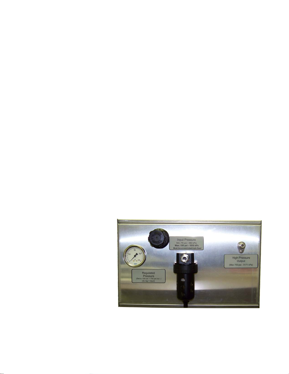
Input Pressure Port
The input pressure port labeled
“INPUT PRESSURE” is used to
supply and drive the booster and
is intended to be connected to a
shop air supply of 70 to 150 psi
(150 psi max). The port is a 3/8”
male Swagelok type tube fitting
mounted on the end of a pressure
filter. A 200 psi rear mounted
panel gauge provides an
indication of the regulated shop
air pressure input. If shop air is
not present on the gauge the user
should check to see if the shop
air is present on the input port
and the regulator knob is not fully counterclockwise. The input regulator filter provides basic
filtering of large particles and liquids.It should periodically be checked for excessive
contamination and emptied of liquids. Note: The input pressure supply should have

sufficient capacity (flow) to maintain the input pressure setting. Failure to do so may
cause the booster to short cycle and not be able to achieve the desired output pressure. If
external regulators are in line with the shop air supply, make sure that they do not restrict the
input flow. Also use large diameter supply hoses (3/8” or larger) is recommended.
High Pressure Output Port
The output pressure port is a ¼” male Swagelok type tube fitting. The actual output pressure
can be monitored with the pressure gauge located on the front panel. The output pressure is a
combination of the raw input supply pressure plus four times the regulated pressure as read on
the Regulator Pressure gauge. It can be adjusted with the black Regulator Adjustment Knob.
OPERATION
While operation of the booster system is quite simple, high pressure gas is dangerous.
NOTE: Operation of this unit and maintenance of this unit should be performed by
qualified personnel only.
1. Connect a low pressure supply such as shop air to the “INPUT PRESSURE” port.
The system requires a minimum of 60 psito obtain 300 psi output.
2. Connect the load (pressure controller) to the ‘HIGH PRESSURE OUTPUT” port.
Be careful to use tubing rated for the boosted working pressure.
3. Slowly apply shop air to the “INPUT PRESSURE” port while monitoring the
“OUTPUT PRESSURE” gauge on the front of the unit.
For most applications, the booster
piston temperatures will not be a
problem. However, if a particular
application causes the booster piston
to operate frequently, the high
pressure end of the booster cylinder
may overheat. Temperatures in the
cylinder above 300 degrees F will
considerably shorten the life of the
piston seal. Temperatures can be
minimized by reducing the drive
speed while still maintaining the output pressure, but at a slower recharge rate. The drive
speed is adjusted by removing the top cover and adjusting the yellow ball valve lever. The
unit is shipped with this lever in the wide open position. Experience has shown, that under
all but the most extreme conditions, temperature problems should be of no concern.
DISCONTINUE OPERATION
To discontinue operation of the booster system:
Rear View

1. Valve off any pressure going to the “INPUT PRESSURE” port. Disconnect the
supply gas if desired. Alternately, the Regulator Pressure knob can be adjusted until
the regulator pressure reads zero.
2. With the input pressure shut off, slowly vent the output pressure by cracking the
output connector to let the pressure slowly release or by continually cycling the
controller between an acceptable control pressure and vent until pressure is drained.
Maintain a safe noise level when venting. Wait until the output gauge reads 0 psi
before disconnecting the controller or load.
TROUBLESHOOTING
This section provides simple operational checks. The Haskel AAD-5 manual attached
contains additional information.
If the unit does not pump…
1. Verify that the “INPUT PRESSURE” has pressure applied.
2. Verify that the regulator pressure knob is slightly open and the Regulator Pressure
gauge reads approximately 50 to 150 psi (just not at zero).
If the unit continually cycles after reaching pressure and the temperature of the gas has
stabilized or when cycling occurs when not being used….
1. Check for leaks in the system. Use a leak detector to track down and correct the
problem.
MAINTENANCE
NOTE: High Pressure Gas can be dangerous. Maintenance of this unit
should be performed by fully qualified personnel only.
Booster Unit:
The control valve and the pilot valves on the Haskel Booster may occasionally need re-
lubrication on units experiencing a high amount of use. Instructions and a special lubricant
are provided in the Haskel manuals in the Appendix.
Drive Pressure Filters
Each booster is equipped with a filter and regulator. The filters should be inspected on a
regular basis. Drain any accumulated moisture or sludge through the drain petcock on the base
of the filter.
Occasionally, clean the internal filter element inside the filter sediment bowl. To access the
element, first disconnect all pressures from the system. Unscrew the filter bowl ring nut by
hand and remove the bowl and filter element screw.

Clean the bowl with either soapy water or kerosene. Clean the element with a cleaning
solvent. Dry all the parts and reassemble. Make sure that the o-ring seal for the bowl is
properly positioned, replace the bowl and tighten the ring nut by hand.
The Haskel recommended maintenance schedule is listed in the appendix.

High Pressure
Output Gauge
Front View
Regulator Adjust
Regulator Gauge
(50 to 150 psi)
Input Pressure
Filter (See
Maintenance
Section)
High Pressure
Output Port
(750 PSI Max.)
Moisture Trap
Release Valve
Speed Adjust Lever
(located inside chassis)
Input Pressure Port
150 psi Max.
Rear View

SPECIFICATIONS
Input Pressure:
Dry Compressed air or Nitrogen at a maximum of 150 PSI (1.03 MPa)
Output Pressure:
Compressed air or Nitrogen up to 750 psi with appropriate supply pressure
Not to exceed 750 psi maximum.
Charge Noise Level:
Approximately 80 dbA intermittent pulses measured at 1 meter
Weight:
45 lbs or 20.4 kg
Size: Rack Mounted 7U Chassis,
19” wide, 10.5” tall, 17.25” deep (482.6 mm x 266.7 mm x 438.15 mm)
(User accessible filter extends depth by an additional 5” or 127 mm in the rear.)

APPENDIX
Haskel Operating and Maintenance Instructions

Mensor Corporation
201 Barnes Drive
San Marcos, Texas 78666-5994
Phone: 512.396.4200
Fax: 512.396.1820
Web site: www.mensor.com
E-mail: sales@mensor.com
Table of contents
Popular Extender manuals by other brands


Network Technologies
Network Technologies ST-C5USBV-300M Installation and operation manual

Transition Networks
Transition Networks CCSCF3011-110 user guide

Atlona
Atlona AT-AVGA-SR user manual

G&D
G&D CATVision Installation and operation

Texecom
Texecom Premier Elite 32XP-W installation manual

Eneo
Eneo ENX-900P installation guide


