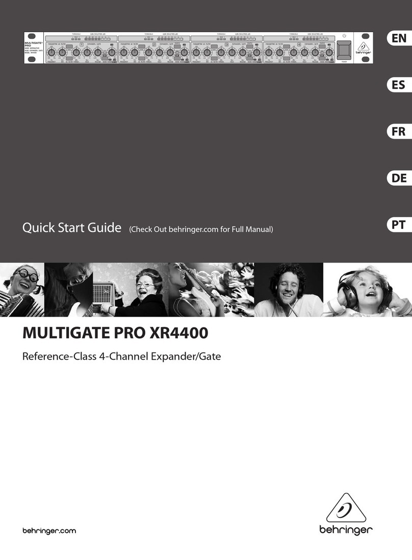
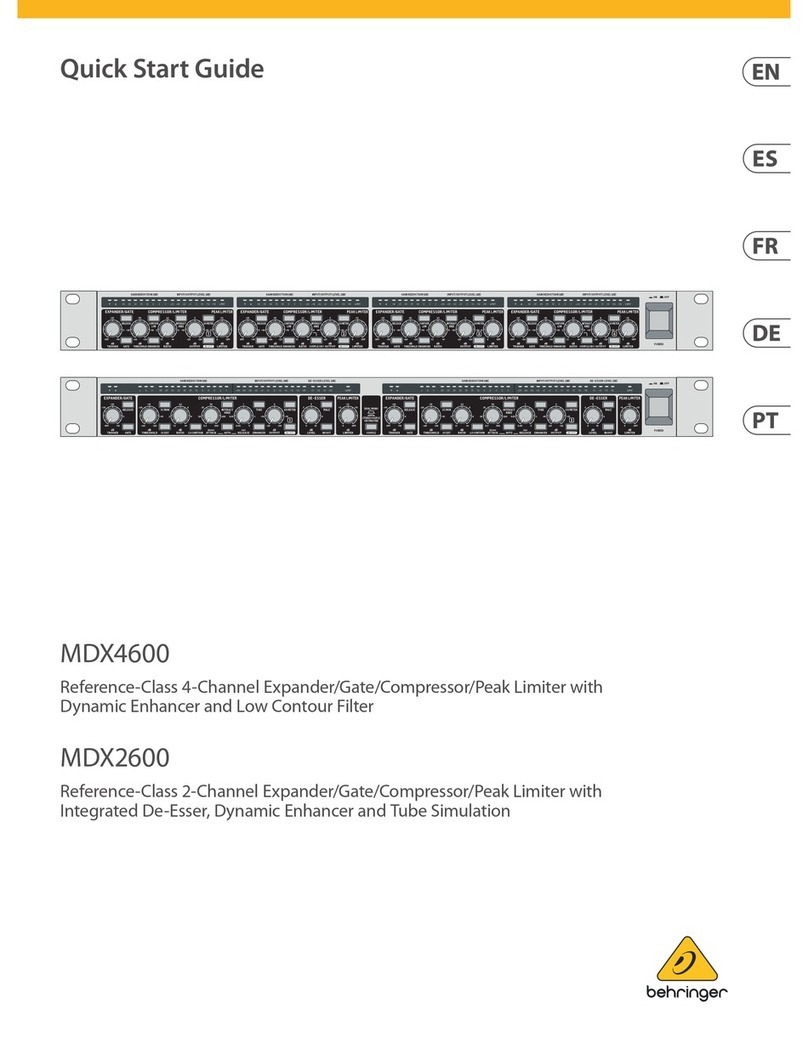
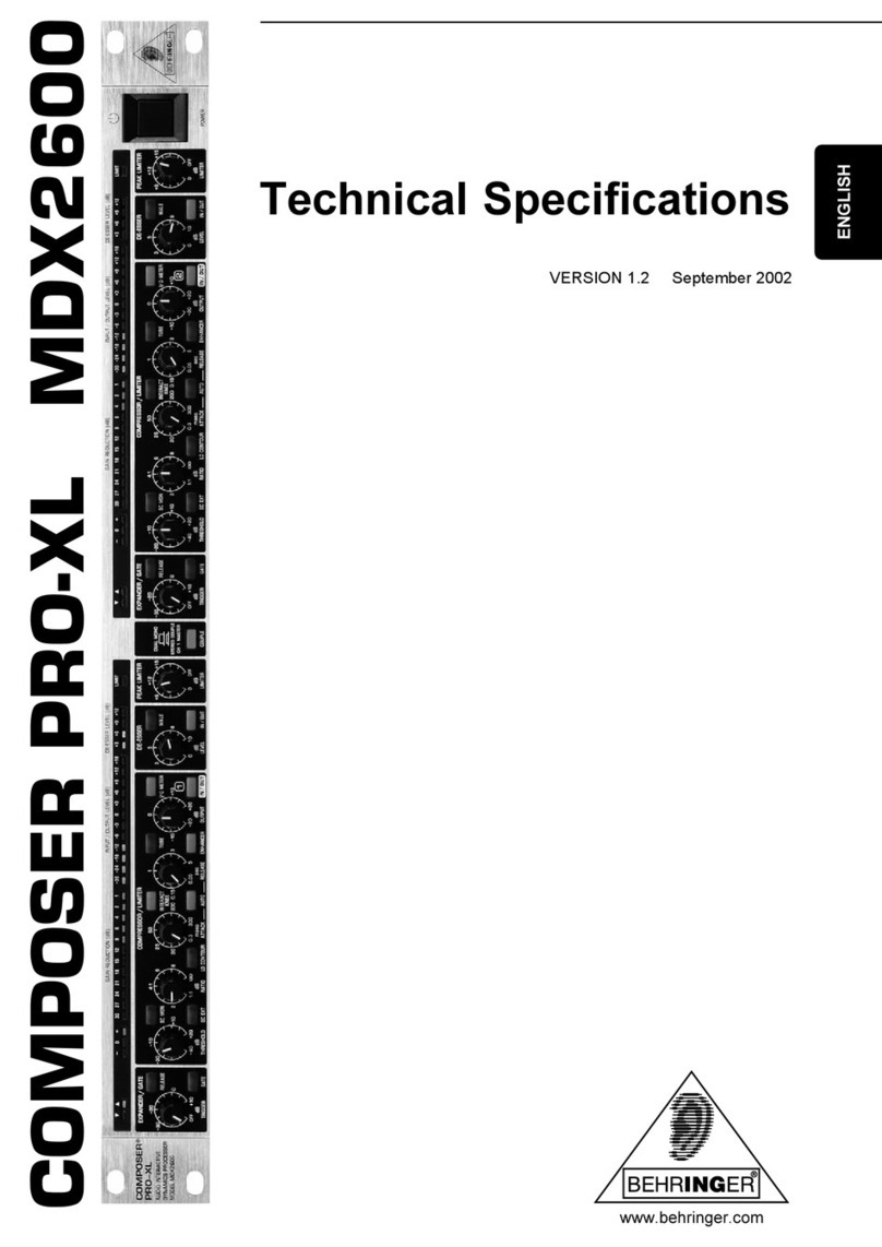
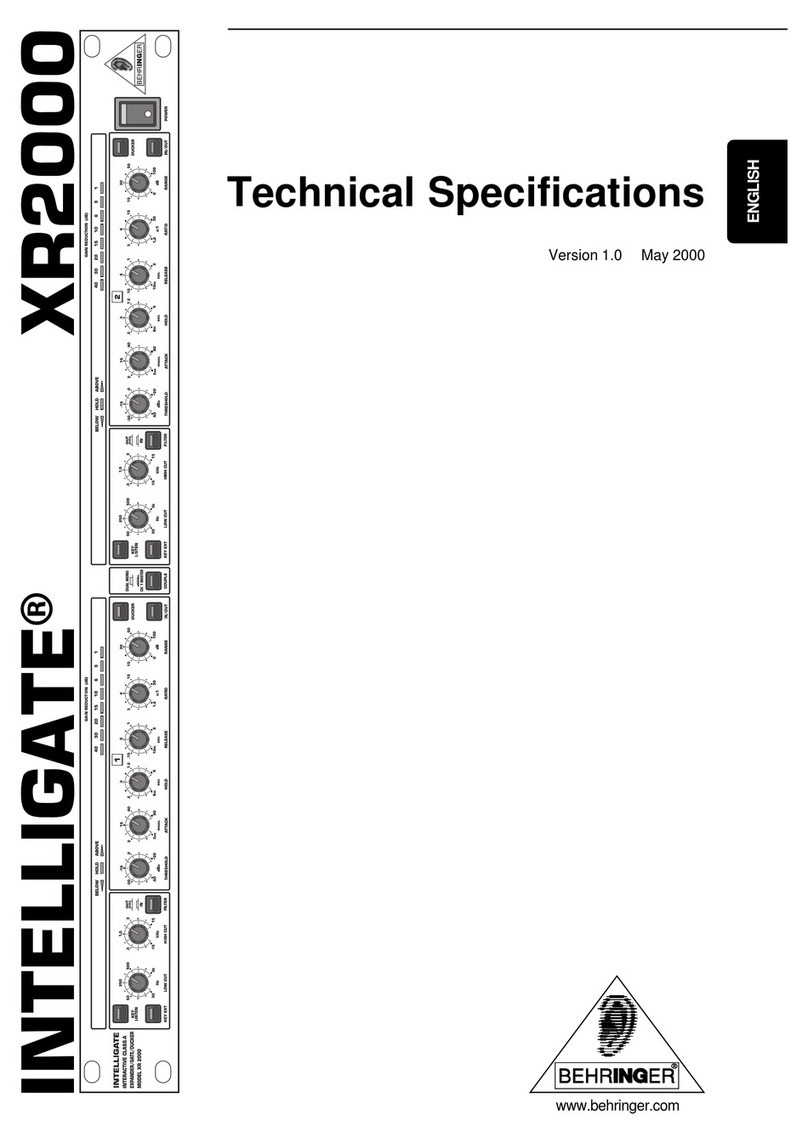
Behringer Intelligate XR2000 User manual

Version 1.2 January 2001
INTELLIGATE®
XR2000
www.behringer.com
User’s Manual
ENGLISH

2
INTELLIGATEXR2000
Thissymbol,whereveritappears,alerts
you to the presence of uninsulated
dangerousvoltageinsidetheenclosure
– voltage that may be sufficient to
constitute a risk of shock.
This symbol, wherever it appears, alerts
you to important operating and
maintenance instructions in the
accompanying literature. Read the
manual.
SAFETY INSTRUCTIONS
CAUTION: To reducethe risk of electrical shock,do not remove
thecover(orback).Nouser serviceable parts inside;
referservicing to qualifiedpersonnel.
WARNING: To reduce the risk of fire or electrical shock, do not
expose this appliance to rain or moisture.
DETAILEDSAFETYINSTRUCTIONS:
Allthesafety and operation instructions should be readbeforethe appliance is operated.
RetainInstructions:
Thesafetyandoperatinginstructions should be retained for future reference.
Heed Warnings:
Allwarnings on the applianceand in the operatinginstructions should be adhered to.
Followinstructions:
Alloperationanduser instructions should be followed.
Water and Moisture:
Theappliance should notbeusednear water (e.g.nearabathtub, washbowl, kitchensink,laundrytub, in awet
basement, or near a swimming pool etc.).
Ventilation:
Theapplianceshould be situated sothatitslocation or position doesnotinterferewithits proper ventilaton. For
example, the appliance should not be situated on a bed, sofa rug, or similar surface that may block the
ventilation openings: or placed in a built-in installation, such as a bookcase or cabinet that may impede the
flowofairthrough the ventilation openings.
Heat:
The appliance should be situated away from heat sources such as radiators, heat registers, stoves, or other
appliances(includingamplifiers)thatproduceheat.
Power Source:
Theapplianceshould be connected to a power supply only ofthetypedescribed in the operating instructions
or as marked on the appliance.
Grounding or Polarization:
Precautionsshould be taken sothat the grounding or polarization means of an appliance is not defeated.
Power-Cord Protection:
Power supply cords should be routed so that they are not likely to be walked on or pinched by items placed
upon or against them, paying particular attention to cords and plugs, convenience receptacles and the point
wheretheyexit from the appliance.
Cleaning:
Theapplianceshouldbecleanedonlyasrecommendedbythemanufacturer.
Non-usePeriods:
Thepower cord oftheapplianceshould beunpluggedfromthe outletwhenleftunused for alongperiodof time.
Object and Liquid Entry:
Careshouldbe taken so that objects do notfallandliquidsarenot spilled into the enclosure through openings.
Damage Requiring Service:
Theapplianceshould be serviced by qualifiedservicepersonnelwhen:
- the power supply cord or the plug has been damaged; or
- objects have fallen, or liquid has been spilled into the appliance; or
- the appliance has been exposed to rain; or
-theappliance does not appear to operate normallyorexhibits a marked change in performance; or
-theappliancehasbeendropped,ortheenclosuredamaged.
Servicing:
TheusershouldnotattempttoservicetheappliancebeyondthatwhichisdescribedintheOperatingInstructions.
Allotherservicingshould be referred to qualified service personnel.

3
INTELLIGATEXR2000
FOREWORD
DearCustomer,
Welcome to the team of INTELLIGATE users and thank you very much for expressing your confidence in
BEHRINGER products by purchasing the XR2000. It is one of my most pleasant tasks to write this letter to
you, because it is the culmination of many months of hard work delivered by our engineering team to reach a
veryambitiousgoal:Topresentyouwithanoutstandingproductwhoseflexibility makes it an ideal tool both in
studioandlivesound environments. The task to design the new INTELLIGATE certainlymeantagreatdealof
responsibility,whichwe assumed by focusing on you, the discerninguserandmusician. It also meant a lot of
work and night shifts to accomplish this goal. But it was fun, too. Developing a product usually brings a lot of
peopletogether,andwhat a great feeling it is when everybody who participatedinsuchaprojectcanbeproud
ofwhatwe’veachieved.
Itisour philosophy to share ourjoywithyou,because you are the mostimportantmemberoftheBEHRINGER
team. With your highly competent suggestions for new products you’ve greatly contributed to shaping our
companyandmakingit successful. In return, we guarantee youuncompromisingquality(manufacturedunder
ISO9000 certified management system) as well as excellent technical and audio properties at an extremely
favorable price. All of this will enable you to fully unfold your creativity without being hampered by budget
constraints.
Weareoftenasked how we can make it to produce such high-gradedevicesatsuch unbelievably low prices.
The answer is quite simple: it’s you, our customers! Many satisfied customers means large sales volumes
enablingus to get betterconditions of purchase forcomponents, etc. Isn’t itonly fair to passthis benefit back
to you? Because we know that your success is our success, too!
Iwouldliketothank all people whose help on “Project INTELLIGATE” has made itallpossible.Everybodyhas
made very personal contributions, starting from the designers of the unit to the many staff members in our
company and finally to you, the user of BEHRINGER products.
Myfriends, it’s been worth the trouble!
Thankyouverymuch,
UliBehringer

4
INTELLIGATEXR2000
XR2000XR2000
XR2000XR2000
XR2000
INTELLIGATE®
Interactive Class-A Expander/Gate/Ducker
VHighprecisionkeyfiltersforfrequencyselectiveoperation
VUltra-fastgate(<3 µsec.) employing the UTR (Ultra Transient Response) circuit
VIRC(InteractiveRatioControl)expandercircuiteliminates“chatter”onoraround the threshold point
VFullyadjustableratio control in Expander mode
VFullyadjustableattenuation control in Gate mode
VIndependenthold/release controls foranyenvelopeshaping
VKey listen facility for monitoring the filter section
VHigh-performanceClass-A VCA’s
VUltralow-noise4580 audio operational amplifiersforoutstandingsound performance
VPrecise gain reduction display with 8 LED’s
VAccurate“TrafficLight”display for easy threshold setting
VTrueRMS level detectionfor“inaudible” performance
VServo-balancedinputs and outputs
VGold-platedXLRand 1/4" TRS connectors
VHigh-qualitydetentedpotentiometersandilluminatedswitches
VManufacturedunderISO9000 certified management system

5
INTELLIGATEXR2000
TABLE OF CONTENTS
1. INTRODUCTION ........................................................................................................................................................ 6
1.1 Before you begin.............................................................................................................................................. 6
1.2 Control elements ............................................................................................................................................. 7
1.2.1 Front panel............................................................................................................................................ 8
1.2.2 Rear panel............................................................................................................................................ 9
2. OPERATION ............................................................................................................................................................ 10
2.1 Functions of the Expander............................................................................................................................. 10
2.2 Interactive control functions ........................................................................................................................... 10
2.2.1 THRESHOLD control.......................................................................................................................... 11
2.2.2 ATTACK-, RELEASE- and HOLD controls.......................................................................................... 11
2.2.3 RANGE control.................................................................................................................................... 12
2.2.4 IRC (Interactive Ratio Control)-EXPANDER ....................................................................................... 12
2.3 RATIOcontrol ................................................................................................................................................. 12
2.4 GAIN REDUCTION meter .............................................................................................................................. 13
2.5 COUPLE function........................................................................................................................................... 13
2.6 DUCKER function .......................................................................................................................................... 13
2.7 KEYFILTERS ................................................................................................................................................. 13
2.7.1 KEYEXT function ................................................................................................................................ 13
2.7.2 KEY LISTEN function .......................................................................................................................... 13
3. APPLICATIONS ...................................................................................................................................................... 14
3.1 Initial settings................................................................................................................................................. 14
3.1.1 The gating function ............................................................................................................................. 14
3.1.2 The EXPANDER function .................................................................................................................... 15
3.2 Correct microphone placement .................................................................................................................... 16
3.3 Frequency selective expansion ..................................................................................................................... 16
3.4 Main applications........................................................................................................................................... 16
3.4.1 Controlling leakage in the studio ....................................................................................................... 16
3.4.2 Reducing leakage in stage mics ....................................................................................................... 17
3.4.3 Reducing feedback in stage mics ..................................................................................................... 17
3.4.4 Noise reduction on effects paths ....................................................................................................... 17
3.5 Using the INTELLIGATE to change the sound .............................................................................................. 18
3.5.1 Reshaping sample sounds............................................................................................................... 18
3.5.2 Altering the texture of musical instruments ....................................................................................... 18
4. SPECIALAPPLICATIONS ....................................................................................................................................... 18
4.1 The INTELLIGATE as “De-Esser” .................................................................................................................. 18
4.2 Frequency selective operation....................................................................................................................... 19
4.2.1 Frequency selective filtering of unwanted signals............................................................................. 19
4.2.2 Suppressing instruments during recording ...................................................................................... 19
4.2.3 Reducing feedback in PA systems..................................................................................................... 19
5. EXTERNALSIDECHAINAPPLICATIONS ................................................................................................................ 20
5.1 The “Key External” function ............................................................................................................................ 20
5.2 Using an equalizer in the sidechain path ..................................................................................................... 20
5.3 “Voice Over” applications ............................................................................................................................... 21
5.3.1 The “Voice Over” application in conference room situations............................................................. 21
5.4 Anticipated expansion ................................................................................................................................... 22
5.5 Triggering additional sounds from a rhythm track ........................................................................................ 22
6. INSTALLATION ....................................................................................................................................................... 23
6.1 Mains voltage ................................................................................................................................................. 23
6.2 Audio connections ......................................................................................................................................... 23
7. SPECIFICATIONS.................................................................................................................................................... 24
8. WARRANTY ............................................................................................................................................................ 26
6
INTELLIGATEXR2000
1. INTRODUCTION
Inpurchasingthe INTELLIGATE, you have acquiredanextremelyefficientanduniversal dynamics processor.
The unit is a versatile, high quality expander, gate and ducker for recording and broadcast situations, post
productionsuits etc.Itcan thereforebeusedforrecordingoreliminatingnoise inaudiorecordings, automatically
shutting down open mics in PA systems, increasing dynamics in heavily compressed music, improving the
dynamic range of noisy communication systems, creating special effects for varying sound styles etc.
AdvancedBEHRINGER Technology
Despite the extremely complex internal circuitry, the unit has a control surface which is clearly laid out and
easy to understand. The internal design of the unit, together with its external sidechain path, gives the user
unsurpassedcreativeflexibilitywhenprocessingsound.
TheBEHRINGERINTELLIGATEcontainsseveralnewcircuitdesignswhichmaketheunittheultimateexpander/
gate/ducker.
UTR (Ultra Transient Response) Gate
Withanattacktimeof3µs,the BEHRINGER INTELLIGATE is one ofthefastestgatesknown,thathavebeen
designed.An extremely quickattacktimeis necessary forveryfasttransients, e.g. forhandclapsor percussive
instruments, so that the gate does not loose the initial transients and affect the sound.
ThenewUTR(UltraTransientResponse) circuit, in conjunction with a Class-A VCA circuit, the unit allows for
instantaneous attack parameters without the all too familiar, nightmarish switching noise, found when using
conventionalgates.
IRC (Interactive Ratio Control) Expander
A basic problem in the use of a noise-gate is that generally these devices provide you with little more than a
simple “on/off” switch. When attempting to fade noise out of complex programme material, the unit would
inadvertentlycreateundesirable side effects.
Toeliminatethisproblem,one would use an additional expander, which would create a continuous andgently
fade.However,simpleexpanders,evenwhentheyareusedcorrectly,drasticallycutsignalsbelowthepreset
threshold.Thiseffectbecomesmorenoticeableduringthetransitionfromsignaltonoisefloor.Thiscanmean
that the start or end of words can be cut on a vocal track.
AnewlydevelopedIRC(InteractiveRatioControl)expanderhasbeenintegratedintotheINTELLIGATE.The
ratioofwhich, is automatically adjusted, dependent on programme material.Theresult is an expander which
isless critical of adjustment and whichis more tolerant in the presenceof those signals which appear slightly
abovethe noise floor.
Inconjunction with the gatefunction,theIRC expander isanexcellenttool for allassociatedsoundengineering
situations. Additionally, the extensive control parameters allow for a focussed and successful solution whilst
processing all types of programme material. Without compromise, the unit meets the highest demands with
regardtooperation,sound,specificationsandmanufacture.
This manual first describes the terminology used, so that you can fully understand the
INTELLIGATEand its functions. Pleaseread the manualcarefully and keep itfor future reference.
1.1 Before you begin
YourINTELLIGATEwascarefullypackedinthefactoryandthepackagingisdesignedtoprotecttheunitfrom
rough handling. Nevertheless, we recommend that you carefully examine the packaging and its contents for
anysigns of physical damage,which may have occurred during transit.
If the unit is damaged, please do not return it to BEHRINGER, but notify your dealer and the
shipping company immediately, otherwise claims for damage or replacement may not be
granted. Shipping claims must be made by the consignee.
1. INTRODUCTION

7
INTELLIGATEXR2000
TheBEHRINGERINTELLIGATEfitsinto one standard 19" rack unit of space (1 3/4"). Pleaseallowatleastan
additional4"depth for the connectorsonthebackpanel. Be sure thatthereisenoughair space around theunit
forcoolingandplease do not place the INTELLIGATE on high temperaturedevicessuchas power amplifiers
etc.to avoid overheating.
Before you connect your INTELLIGATE to the mains, please make sure that your local voltage
matches the voltage required by the unit:
Thefuseholderonthefemalemainsconnectorhas3triangularmarkers,withtwoofthesetrianglesopposing
eachother.Your INTELLIGATE is set to theoperatingvoltageprintednexttothese markers, and can be setto
another voltage by turning the fuse holder by 180°. CAUTION: this instruction does not apply to export
models exclusively designed, e.g. for 115 V operation!
The mains connection of the INTELLIGATE is made by using the enclosed mains cable and a standard IEC
receptacle.Itmeets all of the international safetycertificationrequirements.
Please make sure that all units have a proper ground connection. For your own safety, never
remove or disable the ground connector of the unit or of the AC power cable.
Asstandard, theBEHRINGERINTELLIGATE isinstalledwith electronicallyservo-balancedinputsand outputs.
The new circuit design features automatic hum and noise reduction for balanced signals and thus allows for
trouble-free operation, even at high operating levels. Externally induced mains hum etc., will be effectively
suppressed.Theautomatic servo-function recognizesthepresenceof unbalanced connectors andadjuststhe
nominallevelinternallytoavoidleveldifferencesbetweentheinputand output (correction 6 dB).
Youwillfind additional information in chapter6“INSTALLATION”.
1.2 Control elements
Fig. 1.1: The control surface of the INTELLIGATE
The BEHRINGER INTELLIGATE has two indentical channels. Each channel is equipped with 5 push button
switches, 8 rotery controls and 11 LEDs. The COUPLE switch is for stereo operation:
1
The INTELLIGATE converts to stereo mode by engaging the COUPLE switch, where the left channel
assumesthecontrolofbothaudiopaths,wherebythecontrolvoltageofchannel2 will be replaced with
that of channel 1. By depressing the COUPLE switch, you overide all the controls and switches of
channel2 withtheexception oftheIN/OUT andtheKEYLISTENswitch.Channel1’s controlscompletely
takeoverthefunctions of channel 2.
1. INTRODUCTION

8
INTELLIGATEXR2000
1.2.1 Front panel
Fig. 1.2: Control elements of the Expander section
2
The IN/OUT switch engages the corresponding channel. This switch is used to make direct A/B
comparisonsbetweensourcematerialandtheprocessor’s effected signal.
3
TheTHRESHOLDcontroladjusts the thresholdlevelfortheexpander/gate section intherangeof-50 to
+20 dBu. Signals below this level cause attenuation. As the key signal passes through threshold, the
releaseand holdfunctionsare triggered,droppingthegainoftheExpander/Gate tothevalue determined
bythe RANGE control . In Ducker mode thesefuntionsare reversed.
4
The ATTACK controladjusts the time taken to reach unity gain afterthe key signal exceeds threshold.
When in the Ducker mode, this control adjusts the rate of attenuation after the key signal exceeds the
threshold. The control range lies between 3 µsand 90milliseconds.
5
The HOLD control adjusts the period of delay before the onset of the release function, after the signal
falls below the threshold. The control range lies between 8 milliseconds and 4 seconds.
6
The RELEASE control adjusts the time taken for the gain to be reduced to a value set by the RANGE
control. When in the Ducker mode, this control adjusts the rate of recovery to unity gain after the hold
cycle is complete. The control range lies between 10 milliseconds and 2 seconds.
7
UsetheRATIO control to adjust the ratio ofthedownwardexpander.Itdefines the relationship between
theinput and theoutputlevelwhich fall belowthethreshold.The control rangeliesbetween1.2:1to 30:1.
8
The RANGE control determines the maximum amount of attenuation. The control range lies between
0 dB up to 100 dB.
9
The DUCKER switch changes the operation from the Expander to the Ducker and the control signal is
inverted.Whenthe key signal exceeds the threshold, the gainofthe Ducker is now decreased and the
output is returned to unity gain when the key signal falls below the threshold.
10
The arrangement of the LEDs in this application is called “traffic lights” and indicates the operating
status of the unit. The BELOW LED (red) indicates that the key signal is below threshold. The HOLD
LED (yellow) indicates that the hold circuit is active. The ABOVE LED (green) indicates that the key
signalisabovethreshold.
11
The 8-stage GAIN REDUCTION meter informs you of the actual gain reduction and displays this in a
range of 0 to 40 dB.
1. INTRODUCTION

9
INTELLIGATEXR2000
Fig. 1.3: Control elements of the Key Filter section
12
The tunable Key Filter section is switched into the sidechain path when the FILTER switch is pressed.
13
TheLOW CUT control adjusts the cut-off frequency at whichthehighpassfilterrollsoff low frequencies
in the sidechain path. It has a slope of 12 dB/octave and has a control range from 30 Hz to 3 kHz.
14
TheHIGHCUTcontrol adjuststhecutt-offfrequency atwhichthe lowpassfilter rollsthehighfrequencies
in the sidechain path. It has a slope of 12 dB/octave and has a control range from 150 Hz to 15 kHz.
15
Using the KEY LISTEN switch will enable you to connect the key control signal to the audio output,
whilstatthesametime muting the audio input. This function provides you with theabilitytomonitorthe
key signal, that is returned via inserted equalizers or other external processors. The KEY LISTEN
functionwill assist you with tuning equalizer parameters for example.
Please note when the KEY LISTEN switch in engaged, the audio processing facility of the
respective channel is disabled. When this function is active, a visual indication will be provided
by the switches LED.
16
Whenactivated, the KEYEXTswitchseveres the connectionbetweentheaudio input andthesidechain
path,whilstatthesametimeallowinganexternalsignaltobesourcedattheKEYRETURNjackonthe
rearpanel.
1.2.2 Rear panel
Fig. 1.4: Rear panel of the INTELLIGATE
17
SERIAL NUMBER. Please take the time to have the warranty card filled out completely, and return it
within14daysafterthedate of purchase, so as to be entitled to benefit from our extended warranty.Or
useouronlineregistrationoptionavailableontheWorldWideWebunderwww.behringer.com.
18
Use the enclosed power cord to connect the unit to the mains.
19
FUSEHOLDER /VOLTAGESELECTOR.Pleasemakesure thatyourlocal voltagematchesthevoltage
indicated on the unit, before you attempt to connect and operate the INTELLIGATE. Blown fuses may
onlybereplacedby fuses of the same type and rating. Some modelsallowforinserting the fuse holder
intwodifferent positions, in order to switch overfrom230 V to 115 V operation, andviceversa. Please
note that for 115 V operation outside Europe, you need to use a fuse of a higher rating (see chapter 6
“INSTALLATION”).
1. INTRODUCTION

10
INTELLIGATEXR2000
20
AUDIOIN.ThesearetheINTELLIGATE’saudioinputs.
21
AUDIOOUT.ThesearetheINTELLIGATE’s audio outputs.
22
KEY SEND. This is the key signal output for the connection of external units.
23
KEY RETURN. This is the key signal input for the connection of external units.
2. OPERATION
2.1 Functions of the Expander
As already described, a downward expander automatically reduces the overall level for all signals below an
adjustablethresholdandthereforeextendsthedynamicrangeoftheprogrammematerial.Theexpandertherefore
operates in an opposite way to that of a compressor. Expanders generally function with a flat ratio curve, so
that the signal continually fades.
Noice-gates,however, canbeseen asaspecial typeofexpander. Theynormallywork withamoreexaggerated
ratio and radically attenuate the signal if it falls below the threshold.
The following explanations also apply to the gate function, because the gate is a special form
of the expander.
Fig. 2.1: The function of an Expander
2.2 Interactive control functions
LiketheCOMPOSER PRO MDX2200, MULTICOM PRO MDX4400, and others, theINTELLIGATEusesthe
newly developed INTERACTIVE principle based on a chain of intelligent control functions. For example, the
IRCexpander (Interactive RatioControl)doesnot use afixedratiocurve but variesthiscurvedepending on the
inputlevelandthesettingoftheTHRESHOLDcontrol.
Thefollowingchapterdescribestheinteractivecontrol functions in full detail:
2. OPERATION

11
INTELLIGATEXR2000
2.2.1 THRESHOLDcontrol
TheTHRESHOLDcontrol oftheExpander definestheoperating level.Itstretchesacrossaverywiderangeand
thereforeappliestoallworkinglevels.
Inputlevelsabove the adjusted threshold pointdonotexperienceany change. However, if thelevelfallsbelow
thethreshold, thedynamicsprocess isactive.Simple noise-gatesonlyprovide youwithone controlforadjusting
thethreshold.Controlsfor varying the envelope parameters are omitted.
The BEHRINGER INTELLIGATE is equipped with a full complement of controls to adjust all the required
parameters.How important these parameters are,will be discussed in moredetail in subsequent chapters.
2.2.2 ATTACK-,RELEASE- and HOLDcontrols
TheBEHRINGER INTELLIGATE providesyouwiththree controls fordefiningtheenvelope shape:
Fig.2.2:Theenvelopeprinciple
ATTACKcontrol
The quality of an expander/gate is essentially determined by a fast attack time. It is defined as the amount of
time that the expander/gate needs to return to unity gain, once the signal has exceeded the threshold.
Anextremelyquickattacktimeis necessaryforveryfasttransients,e.g.forhandclapsor percussiveinstruments,
so that the expander does not loose the initial transients and affect the sound.
ThenewUTR(UltraTransientResponse) circuit, in conjunction with a Class-A VCA circuit, the unit allows for
instantaneousattackparameterswithout thealltoofamiliarswitching noisefoundwhenusingmostconventional
gates.
ThewidecontrolrangeoftheATTACKcontrolalsoallowsfor a gentle rise time of a signal, in order to produce
creativeeffects.
RELEASEcontrol
Another parameter is the release time: this determines the time that an expander requires to attenuate the
signal by a certain amount, after it has fallen below the threshold.
The most suitable release time is entirely dependent on the programme material. In order to adapt to the
programmematerial,the INTELLIGATE can be adjusted so that it operatesinawide range.
HOLDcontrol
The HOLD controlproduces an adjustable delay,which holds off theonset of the releasecycle when the key
signalfallsbelowthethreshold. This function is especially useful during the recording offrequentlyinterrupted
signals, e.g. a spoken word recording or perfomance, to avoid repeated triggering of the gate in between
pauses.
2. OPERATION

12
INTELLIGATEXR2000
2.2.3 RANGEcontrol
Thecontrolof the dynamics process intheINTELLIGATEisprovidedby a high performance VCA.Itseffective
range is more than 100 dB, which means that the input signal can be attenuated up to 100 dB.
Inmostapplications, it isnotdesirableforthe signal to begatedoffcompletely when the signaldropsbelowthe
threshold.Thisusuallyintroduceschoppingwithinthesound, especially when there is a significant amount of
backgroundnoise to besuppressed,whichdoes not leadtoanadvantage.The unitincludesaRANGEcontrol,
which adjusts the maximum amount of attenuation. Using this control, it is possible to attenuate the signal
slightly, so that the overall naturalness can be maintained, especially when handling very noisy signals.
2.2.4 IRC (Interactive Ratio Control)-EXPANDER
The response characteristics of conventional expanders tend to cut into the signal abruptly and the result of
thisisunacceptablemost ofthetime.Gainchanges becomeaudible.Inanapplication whichrequires“inaudible”
expansion, it is advantageous to create a gentle “Soft Knee” characteristic during a contiguous transition
throughthethreshold.
Anewlydeveloped IRC (Interactive Radio Control)Expanderhasbeenintegratedinto the INTELLIGATE. The
ratiocurvecharacteristicautomaticallyadaptsitself,dependent on programme material.
Atlowerratioswithreducingexpansion,thetransitionis“gentle”,whereashigherratiosand increasingexpansion
willresultin“harder” transitions within the curve.
TheICR Expanderisthereforeequipped withasoft, interactivenon-linearratiocurve, whichisbest suitedtothe
human hearing. Critical signals in the vicinity of the threshold level are processed with a minute expansion
ratio, whereas signals that reduce in level will be subjected to an increasingly higher ratio which will result in
greaterattenuation.
Fig. 2.3: IRC curve characteristic of the Expander
The result is an expander which is less critical of adjustment and which is more tolerant in the presence of
thosesignalswhichappear slightly above the noise floor.
2.3 RATIO control
The change of output relative to the change of input, when the key signal is below threshold, is called the
expansion ratio, and is adjustable with the RATIO control. This control adjusts an important parameter, it
changes the function of the section from an expander to a gate.
Low ratios, from 1.2:1 about 3:1 produce precisely controlled downward expansion, with more pronounced
effects as the ratio increases to 30:1, where the unit functions as a gate.
The scale of the ratio is calibrated in dB on the front panel. It indicates the decrease in output level, resulting
from a 1 dB decrease in input level.
2. OPERATION

13
INTELLIGATEXR2000
A ratio of 1:1 indicates, that the output signal will correspond to the input signal i.e., there is no level change.
A ratio of 2:1 indicates, that for every 1 dB decrease in input level below the threshold, there will be resultant
corresponding decrease in the output level of 2 dB. A ratio of 30:1 indicates, that for a 1 dB decrease in input
levelbelow the threshold, there will be acorrespondingdecrease in the output level of30dB etc.
2.4 GAIN REDUCTION meter
The GAIN REDUCTION meter consists of eight LEDs on the front panel of the BEHRINGER INTELLIGATE.
This meter provides a convenient visual indication of the amount of gain reduction that is taking place at any
time.Ifa signal exceeds the input level of thethresholdpoint, this function of the compressor comes intoplay
andtheGAINREDUCTIONmetershowstheactualmeasurementofgainreduction.
As an example, consider a signal that drops below the threshold point by 2 dB: with a ratio setting of 6:1, the
outputlevelwillbedecreasedby12dB(providingthetimeandtheRANGEcontrolsaresetaccordingly).This
means that the signal level has been reduced by 12 dB, which is indicated by the 10 dB LED.
Although the VCA of the BEHRINGER INTELLIGATE features a control range of 100 dB, it is not useful to
display the entire range, as in practice, such a broad control range will hardly be required.
Thevisualrangeofthe GAINREDUCTIONmeter is 40 dB.
2.5 COUPLE function
Whenphasecoherentstereo signals are to be expanded, it isnecessaryforthegaincontrolsofbothchannels
oftheexpandertobesimultaneously controlled, otherwise the stereo image will shift within the sound field, as
therelativelevelsofthe left and right signals vary.
WhentheCOUPLEswitchis engaged, the INTELLIGATE functions in stereo mode, whereby the leftchannel
takes over the control of both channels, so that the control voltage in channel 2 is replaced by the control
voltageinchannel1. When the COUPLE switch is activated, all controls and switches belongingtochannel2
are put out of action, with the exception of the KEY LISTEN switch. The controls of channel 1 take over the
regulationof channel 2. Both channels nowworktogether as in a stereo fader.
2.6 DUCKER function
Anexpander or gate opens itsaudio channel, as soon as a certain level has been exceeded. A ducker works
in exactly the opposite way: when the key signal exceeds the threshold point, this will result in an attenuation
of the audio signal. As the key signal drops below the threshold, the audio signal gain returns to unity.
All controls remain active while in Ducker mode.
2.7 KEY FILTERS
Each channel contains an insertable low and high pass filter section which provides you with a slope of
12 dB/octave. The adjustable filters of this highly flexible equalizer can be used to filter out or isolate specific
frequencieswhichwould otherwise create mis-triggering.
2.7.1 KEYEXT function
AnexternalsignalcanbesentviatheKEYRETURNjack,whichallowstheunittobecontrolledexternally.By
engagingtheKEXEXT switch, the BEHRINGER INTELLIGATE can becontrolledexternallye.g. “gating” of an
audiosignalbyan independent control signal.
2.7.2 KEYLISTEN function
Usingthis switch will enable youto connect the key control signal to the audiooutput, whilst at the sametime
mutingtheaudio input. This function provides you with theabilityto monitor the key signal that is returnedvia
insertedequalizersorotherexternalprocessors.The KEY LISTEN function will assist you with tuning the key
filtersorthemonitoringofexternalprocessing devices.
2. OPERATION

14
INTELLIGATEXR2000
Please note when the KEY LISTEN switch is engaged, the audio processing facility of the
respective channel is disabled.
WiththeKEY LISTEN function activated, the key filtersectioncan be used as an independent fully functional
equalizersection.
3. APPLICATIONS
In this section, several typical applications of the BEHRINGER INTELLIGATE are discussed. The following
basic settings can resolve most dynamic problems. They are the ideal starting point. Please take the time to
studytheapplication examples carefully,inordertobe able to makefulluseof the INTELLIGATE’scapabilities
infuture.
Themainapplicationsof the BEHRINGER INTELLIGATE canbedividedintofourcategories:
1. Toeliminateinterferenceandtosuppressbackgroundnoiseandleakageonindividualtracksinmultitrack
recording.
2. Increasingthedynamicsofheavilycompressedmusic,reshapingsampledsoundenvelopesandcreating
specialeffectsfor varying sound styles.
3. As a ducker in “voice-over” applications, for de-essing and for suppressing sounds during recording and
reducingfeedbackinlivesituations.
4. Using the key filters as an independent equalizer section.
3.1 Initial settings
Different applications require control parameters. We will now illustrate the effects of the controls in some of
theabove applications. Once thefunction of each control is understood, you will find your own applications.
3.1.1 The gating function
Gatingisaso-called“highratio”expanderfunctionandisthesimplestfunctionoftheBEHRINGERINTELLIGATE.
If the expander is used with a ratio of 30:1 and a maximum attenuation (RANGE control fully clockwise), this
is termed “hard” gating. The gate function is used for auto-muting individual tracks in multitrack mixdown,
automaticallyturningoffopen mics when they are not active, eliminating background noise and leakagefrom
adjacent instruments on music tracks and for generating special effects. Especially in the processing of
percussive instruments, it is recommended to use hard gating.
Percussiveinstruments inherentlyexhibitfasttransients. Thefollowingshall bediscussedwith someexamples:
When individual instruments are placed close to each other in a live area or concert hall, room reverberation
and adjacent instrument crosstalk problems during pauses etc. become troublesome, even when the best
closemiking techniques are adopted.Thisundesirableeffect known ascrosstalk,canbe precisely suppressed
usingthe INTELLIGATE.
Set the control and switches to the following positions:
Controls Settings
THRESHOLD control clockwise
ATTACK control anticlockwise
HOLD control anticlockwise
RELEASE control anticlockwise
RATIO control clockwise
RANGE control clockwise
KEY LISTEN switch OUT
KEY EXT switch OUT
FILTER switch OUT
IN/OUT switch IN
Tab. 3.1: Initial settings for the Gating function
3. APPLICATIONS

15
INTELLIGATEXR2000
THRESHOLDcontrol
Now adjust the THRESHOLDcontrol anticlockwise, untilthe softest hit onthe percussion instrument triggers
the Expander so that the desired signal will pass unaffected. Triggering of the Expander will be monitored by
the flash ofthe ABOVE LED.If you have correctlyadjusted the unit, youwill hear theinstrument clearly stand
outfromtheprogrammematerial.
ATTACKcontrol
Most instruments are characterized by their typical initial profile. For example, instruments like piano, guitar,
cymbals etc. are recognized by their short attack and particulary long release time.
Increasingtheattack time changes the envelope, especially onpercussiveinstruments,wherebyhardsounds
generallybecomesofter.
Special attention should be paid to fast attack times! Especially with low frequency signals, such as bass
drum and bass guitar etc. Extreme fast attack times can lead to switching noise (“clicks”). This effect will not
beproducedbythecontrolfeedthroughoftheINTELLIGATE,butbytheabruptcutintothesignal’swaveform
above or below the zero crossing point. A slight prolongation of the attack time or a decrease in the ratio will
help you to avoid this side effect.
HOLDcontrol
Programmematerial (e.g.speechorvocalrecordings) oftencontainsshort pauseswhichcanleadtocontinuous
triggeringoftheexpander. Theholdfunctionpreventspremature shutdownwhichisaproblemwithconventional
gates, by delaying the release process. The result is, that the expander remains active during these short
pauses. After the period of the adjusted hold time, the expander closes the audio channel dependent on the
releasefunction.
RELEASEcontrol
Most percussion instruments have a longer decay time (e.g. the decay of cymbals). By adjusting the release
time, this function offers the ability to follow the fade out of the instrument, in order to maintain the entire
character of the sound. In this way you can prevent a too short release time from affecting the natural decay
andtheadditional ambient sound of the instrument.
For signals with long durations or signals with heavy ambience, it is advantageous, to choose long release
times. You will find, that a fast release time is more preferable for accustic separation of most percussive
sounds, whilst cymbals and tom toms normally benefit from slower release times.
If the controls are set correctly, the drum sounds will be “dry”, “sharp” and clearly defined.
RANGEcontrol
The RANGE control defines the amount of maximum attenuation of the audio signal. For instruments with
longerdecaytimes,itisadvantageoustoadjustthe RANGE control to a mid position, in order not to cut off the
signalcompletely.AlthoughtheINTELLIGATEallowsforamaximumattenuationof100dB,generallyitisnot
useful to attenuate a signal by this value. With noisy signals in particular, it is recommended to limit the
attenuation by a value of 10 to 20 dB, in order not to let the onset of the expander become too noticeable.
3.1.2 TheEXPANDER function
In contrast to the gate function, the expander function is based on gradual attenuation, as soon as the signal
fallsbelowthethresholdlevel.
RATIO control
Withthiscontrol,you determine whether the INTELLIGATE functions as a gate or anexpander.Ifforinstance,
a music programme has been heavily compressed during recording, the lost dynamics can be subsequently
restoredbyacomplimentaryexpansion.Withsome“finger-tip-feeling”,thefollowingcontrolscanbeadjusted
by ear, so that original dynamics can be restored.
It is recommended to adjust the RATIO control to values of about 1.2:1 to 1.6:1 in order to achieve a gentle
expansion and to adjust the THRESHOLD control, so, that the entire dynamic range of the music lies below
the threshold. Adjust the THRESHOLD control in this manner, so that only the loudest passages exceed the
threshold.Thiscan be monitored by the flashing ABOVELED.This will now result in a downward expansion,
which is only restricted by the adjustment of the RANGE control. It is recommended to adjust the RANGE
control to values of about 20 to 30 dB.
3. APPLICATIONS

16
INTELLIGATEXR2000
Similarly, with a fine adjustment of controls mentioned, the dynamic range of an instrument can be artificially
expanded.Expansion can achievegoodresults,expecially with sampledsounds,becausesamplers only have
a heavily restricted dynamic range. When processing drum sounds (e.g. a snare), downward expansion can
resultininsteresting effects. If for instance the thresholdissettoanintermediate level, then only the lower part
of the dynamics will be processed. The decay of the signal follows naturally to the adjusted threshold and is
thenfadedoutmoreintensively.
3.2 Correct microphone placement
Themaintaskofanexpander is to “inaudibly” seperate undesirerable background noise from wanted signals.
Thisprocessrequiresthat the signal level appears slightly above the noise floorinorderforthethresholdlevel
tobedefinedaccurately.
Theoptimumuseoftheexpanderdependsprincipallyonmicrophonetechnique.
Beparticularly careful,whenhighfrequencyinstrumentsarelocatedto thesideor rearofa cardioidmicrophone.
Mostcardioidsexhibit a sharply rising off-axis responsecharacteristicat higher frequencies. If there is onlya
2 or 3 dB difference between the on-axis and off-axis response in the 5 to 10 kHz region, cymbals may leak
excessively into the tom mics and you may have hi-hat spilling all over the snare mic.
Pleasemakefull use of the directional characteristic of themics,to acoustically exclude all other instruments
as much as possible. Make sure that you do everything possible to achieve source separation with good
microphonetechnique.Otherwise the expander is not able to undertake clearacousticseparation.
Neverthelessthereare situations, where even ideally suited microphone techniques cannotprovideyou with
thedesired effect. TheBEHRINGERINTELLIGATE givesyoufrequencyselective expansionasafurther aidto
acousticseparation:
3.3 Frequency selective expansion
Sometimes,itisnecessarytopreventtheexpander fromrespondingtolowfrequencies(rumblesetc.),especially
ifasinger is moving the microphone around onamic-stand. Besides this, there are circumstances, when the
programmematerialiscorruptednotonly byunwanted randomnoise,butalsobythesoundofother instruments.
For example, in a multi-miked drum kit situation, some hi-hat will inevitably leak into the snare mic, some
snare drum into the kick drum mic and so on. Equally when recording on location, you may experience
problemsduetowindor traffic noise or close-by conversation. If the unwanted noise is different inpitchtothe
wantedsound,itisoften possible, by using the key filter section, to prevent the expander from falsetriggering.
Proceedasfollows:
1. DepresstheFILTERand theKEYLISTEN switch.
2. Trywiththehelp of the key filters to extensively filter outundersireablesignalsand at the same time, try to
precisely adjust to the wanted signals.
3. Release the KEY LISTEN switch.
4. ReadjusttheTHRESHOLD controltothe new level situation,sothattheINTELLIGATEonly triggers on the
wantedsignals.
3.4 Main applications
3.4.1 Controlling leakage in the studio
Expander/gatesaremost commonly used tosuppressundesirableleakageof sound from onetracktoanother
duringrecordingorplayback.They are usually used when recording drum kits, where the mics areveryclose
to each other.
Highvolumelevelson individual instruments often cause considerable leakage into all the adjacent micsand
results in conflicting frequency and phase coherence problems, as well as unspecified sounds (“comb” filter
effects). It is vitally important, that every instrument is recorded into a separate mic and that each mix is
individuallygated.
Insert the BEHRINGER INTELLIGATE into a snare drum channel for example and adjust it so that triggering
onlyoccurswhenthesnare drum is played. Each mic should be set to itsmaximumoperatinglevel,monitored
(seeKEYLISTEN switch) and the THRESHOLD levelsetsothat each snare hitsoundsacousticallycleanand
separate.
3. APPLICATIONS

17
INTELLIGATEXR2000
Aswellasthis,anextremelyquick attack time is necessary for very fast transients, so that the expander does
not loose the initial transients and affect the sound.
3.4.2 Reducing leakage in stage mics
TheINTELLIGATEhasmany uses especially inlive-work,onstage and in multi-mikingsituations:awell set up
expandercan effectivelysuppressbackgroundnoise,compressor typepumpingnoise andmicrophoneleakage
etc.withoutproducing any undesirable side effects.
Expandersarecommonly used for processing vocals.Whenspecificallyusedwitha compressor, the distance
and position of the mic in relation to the singer is very critical: the further the distance, the more sensitive the
micistobackgroundnoise.UsetheExpander to eliminate background noise inaudibly, that occurs in pauses
betweenthesinging.Whenusedin live situations, leakage of miked instrumentation is substantially reduced,
as well as other acoustic contaminants in various recording situations.
Ifyou do not haveenoughmics(or INTELLIGATEchannels) to recordeachinstrumentseparately, try to create
sub-groups:putthesnareandmid-toms together, and group the side-toms, bass drum and cymbals together
withthehelp of a mixing console. The aim istosetuptheexpander and to position the groupmicssothateach
strikeonaninstrumentopensaspecificmicandonlythatinstrument is recorded, whilst the other mics remain
muted.
3.4.3 Reducing feedback in stage mics
When a singer is using a vocal mic, their voice effectively stops other sounds from entering the mic. But in
pauses between the singing, the mic will pick up noise from the house PA and monitors, which can lead to
unpleasantfeedbackproblems.
If the INTELLIGATE is inserted into the mic channel, it will shut off the channel when it is not being used,
reducingthepossibility of feedback.
Principally all mics should be included in this application.
Fig. 3.1 Gating a stage mic
3.4.4 Noise reduction on effects paths
The effects rack is one of the mainly overlooked sources of noise in a PA system or recording facility. The
prices of reverb and delay units and harmonizers have fallen drastically over the last number of years, which
have made these units a common feature of small studios and home recording installations. Installations
wherethere are anumberofunits however, considerablyincreasetheoverall noise leveldrastically,sothat the
pleasure in acquiring a new sound effect is diluted in a short period.
Itwill be usefultousethe BEHRINGER INTELLIGATE asthelastcomponent inthechain.We recommend that
you use a slow release time in order to maintain the natural reverb.
3. APPLICATIONS

18
INTELLIGATEXR2000
3.5 Using the INTELLIGATE to change the sound
3.5.1 Reshaping sample sounds
With the help of the BEHRINGER INTELLIGATE, existing or new sampled sounds can be brightened up,
changed or used to create new sounds. The attack times and the dynamics of the sound can be changed as
desired.
3.5.2 Altering the texture of musical instruments
In addition, the INTELLIGATE can be used to change sound characteristics. For example, the quality of
ambienceorreverberationcreatedby an instrument within a room can be modified: when an instrumentstops
decaying,thereverberationof the instrument falls below the user-defined threshold.Thereverberationcanbe
controlledby using the thresholdlevelandthe release timecontrol.Thedecaycharacteristics of theinstrument
canbe controlledusingthe releasecontrol,so thatthenatural characteristicsofthe instrumentcanbe controlled
usingtherelease control, so that the natural characteristics oftheinstrument are preserved or modified quite
radically.
4. SPECIAL APPLICATIONS
4.1 The INTELLIGATE as “De-Esser”
The “de-essing” function can be achieved by using a special application or frequency selective ducking. A
problem often encountered in recording, is the sibilant (Ssss) sound of the human voice. High frequency,
sibilant sounds and pops can procedure very high energy levels which can sometimes cause an otherwise
normalandundistortedvoiceto sound very harsh, shrill and sometimes unintelligible.
In order to reduce the problem associated with sibilance, a ducker can be used frequency consciously. The
unit responds only to selected frequencies and reduces the level temporarily, as soon as sibilant sounds or
popsare detected. Ifthedetectorcircuitregisters an excessiveamountofhigh frequency informationwithinthe
programmematerial,theVCA is activated and the overall levelisreduced.Asthistypeof operation affects the
wholefrequencyrange,thisprocessiscalledbroadband de-essing.
Pleasenotethatthis type of frequency selective ducking is very different from simplefixedequalizationusing
notchfilters, since de-essing has no effect on the signal except at the instant the sibilant occurs. The general
frequencyresponseis principally not affected during this process.
When de-essing, insert the Key Filter section into the sidechain loop by depressing the FILTER switch. With
the help of the key listen function, the centre frequencies of the key filters are then adjusted exactly to match
thefrequenciesofthesibilantsounds.Allotherfrequenciesarefilteredout,sothatwithmaximumattenuation
of these frequency bands, along with a correctly adjusted threshold point, the unit responds solely to the
selected signal being produced by the equalizer. The level of sibilant sounds can therefore be effectively
limited.
Fig. 4.1: The INTELLIGATE as “De-Esser”
4. SPECIALAPPLICATIONS

19
INTELLIGATEXR2000
4. SPECIALAPPLICATIONS
Controls Settings
KEY EXT switch OUT
KEY LISTEN switch OUT
FILTER switch IN
THRESHOLD control +20 dB
RATIO control clockwise
ATTACK control 1 ms
HOLD control anticlockwise
RELEASE control 100 ms
RATIO control clockwise
RANGE control 20 dB
DUCKER switch IN
IN/OUT switch IN
Tab. 4.1: Initial settings for the De-Esser function
Proceedasfollows:
1. Rotate the THRESHOLD control anticlockwise until the GAIN REDUCTION meter shows an appropriate
dropin level.
2. Nowpressthe KEY LISTEN switch andaccuratelyadjustthecorner frequencies of thekeyfilters(generally
6 - 10 kHz) by monitoring, until it is within the range of the sibilants.
3. Release the KEY LISTEN switch and recalibrate the THRESHOLD control, so that the unit only reacts
when the sibilant sound occurs.
Althoughtherecommendedattackandreleasetimesforthisfunctionareproven,thetime parameters can be
adjusted if necessary, to achieve maximum results.
4.2 Frequency selective operation
4.2.1 Frequency selective filtering of unwanted signals
Based on the set-up described in the de-esser section, the unit may also be used to eliminate rumble, hum
andequipmentnoise (air-conditioning systems, camera noise etc.).
Using the KEY LISTEN switch, adjust the frequencies of the key filters to match the unwanted frequencies.
Takecare to decreasetheamplitudes of theunrequiredfrequencies.Proceed nowasdescribedin theprevious
chapter.This willresultinducking oftheselected frequenciesandthus adecreaseinthe gainofthe programme
material.
4.2.2 Suppressing instruments during recording
Anotherfunctionof the BEHRINGER INTELLIGATE allows helpful correctionofpreviouslyrecordedmaterial.
If for example, an excessively loud bass drum needs to be suppressed, reduce all the key filter frequencies
above 150 Hz. This setting causes frequency specific ducking, which reacts as soon as increased energy is
detected in this band. By increasing the threshold level, the ducker can be made to react to loud hits only.
Generally, it can be said that relatively high threshold settings prevent the overall sound from being impaired
and lead to the ducking of solo instruments or very loud sounds.
4.2.3 Reducing feedback in PA systems
Acommonprocedureinsoundsystemset-upisequalizingtheacousticto remove feedback. This is generally
accomplishedbyturningup the system gain to purposely induce feedback,searchingforthecentrefrequency
ofthefeedbackandthen equalizing at that frequency to remove the feedback.
Oncethisfeedback has been attenuated, the systemgainisagainincreasedtoinduce another feedback point
andthe wholeprocedureisrepeated untiltheengineeris satisfiedthatthesignificant problemfrequencieshave
beencorrected. Inspiteof thisequalizingprocess,feedbackremainsadifficult problem.Oftenenough, acoustic
changes occur as the audience enters the room, which again leads to feedback problems. In addition, the
frequencyresponseofthe whole system is modified and thus affected byequalizeroperation.

20
INTELLIGATEXR2000
Dynamic feedback control is a better solution. Similar to the de-esser application, the Key Filter section is
insertedinto the sidechain path bypressing the FILTER switch. Toeffectively suppress feedback, the centre
frequencyofthe filters are correctly adjustedtomatchtheroom’s resonant frequency. This selectedfrequency
nowcontrols the BEHRINGER INTELLIGATE.
Assoonasfeedback occurs, the unit temporarily reduces thesystemgainandthuseffectivelysuppresses the
feedback. In contrast to the technique mentioned above, the frequency response of the PA system is not
affected in any way at all. The use of the BEHRINGER INTELLIGATE in this application can eliminate the
possibilityofspeaker or ear damage.
Fig. 4.2: Reducing feedback in audio systems using the INTELLIGATE
5. EXTERNAL SIDECHAIN APPLICATIONS
5.1 The “Key External” function
The BEHRINGER INTELLIGATE offers an exceptionally usable external facility by using the key external
function. By activating the KEY EXT switch, the INTELLIGATE’s control path is disconnected from the audio
inputandtherefore interrupted. Theaudioinputisrouted to the KEY SENDoutput and the KEY RETURN input
nowreceivesthenewcontrolsignal which is derived from an inserted effects processor.
5.2 Using an equalizer in the sidechain path
It is very common to make the response threshold of an expander/gate frequency-dependent. This is the
reason why the high and low pass filters of the Key Filter section are included.
AlthoughtheKey Filters are providedwithaslopeof 12 dB/octave, thereareapplicationswhichrequire a more
complexfrequencyselection.Ifforexamplefrequencybands, which are not located side by side, are required
to trigger the expander, the internal Key Filter section would not be able to fulfill this demand. The use of an
externalgraphicorparametric equalizer becomes necessary. By depressing theKEYEXTswitch,anexternal
unit can now be inserted into the sidechain path. Additionally the Key Filter section of the INTELLIGATE can
beused by depressing the FILTER switch.
Toretainthe threshold setting of theINTELLIGATE, unwantedfrequenciesshouldbereducedby an equalizer
andthedesiredfrequenciesshould be kept at the same level. Should for example, the expander be controlled
by a narrow mid-frequency band, it is advisable to lower the bass and treble controls. The middle frequency
control remains at 0 dB.
5. EXTERNALSIDECHAINAPPLICATIONS
Other manuals for Intelligate XR2000
1
Table of contents
Other Behringer Extender manuals

Behringer
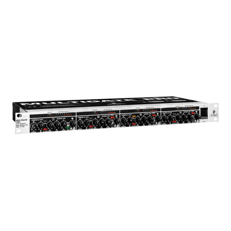
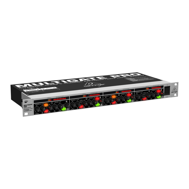
Behringer MULTIGATE PRO XR4400 User manual

Behringer
Behringer MULTICOM PRO-XL MDX4600 User manual

Behringer
Behringer Intelligate XR2000 User manual

Behringer
Behringer COMPOSER PRO-XL MDX2600 User manual

Behringer
Behringer Preamp Booster PB100 User manual

Behringer
Behringer MULTIGATE PRO XR4400 User manual

Behringer
Behringer MULTIGATE PRO XR4400 User manual

Behringer
Behringer MULTIGATE PRO XR4400 User manual