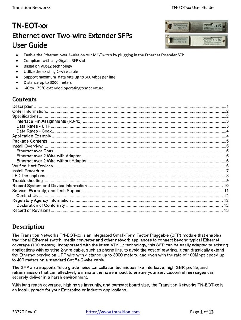
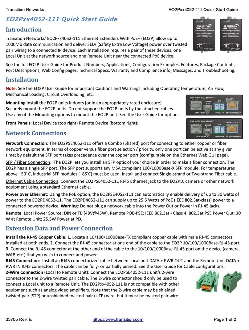
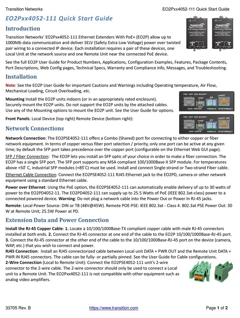
Part Number Port One - Copper Port Two - Single Fiber Optic
2
CCSCF30xx-11x
24-hour Technical Support: 1-800-260-1312 -- International: 00-1-952-941-7600
*Typical maximum cable distance; actual distance is dependent on the physical
characteristics of the network. (TX) = transmit (RX) = receive.
CCSCF3029-111** 75 ohm coax (BNC) SC, 1550 nm (TX)/1310 nm (RX)
single mode, 20 km (12.4 miles)*
CCSCF3029-112** 75 ohm coax (BNC) SC, 1310 nm (TX)/1550 nm (RX)
single mode, 40 km (24.8 miles)*
CCSCF3029-113** 75 ohm coax (BNC) SC, 1550 nm (TX)/1310 nm (RX)
single mode, 40 km (24.8 miles)*
CCSCF3029-115** 75 ohm coax (BNC) SC, 1550 nm (TX)/1310 nm (RX)
single mode, 60km (37.3.miles)*
CCSCF3029-114** 75 ohm coax (BNC) SC, 1310 nm (TX)/1550 nm (RX
single mode, 60km (37.3.miles)*
CCSCF3029-116** 75 ohm coax (BNC) SC, 1310 nm (TX)/1550 nm (RX
single mode, 80km (49.7.miles)*
CCSCF3029-117** 75 ohm coax (BNC) SC, 1550 nm (TX)/1310 nm (RX)
single mode, 80km (49.7.miles)*
CCSCF3040-110 75 ohm coax (BNC) SFP empty slot
CCSCF3029-110** 75 ohm coax (BNC) SC, 1310 nm (TX)/1550 nm (RX)
single mode, 20 km (12.4 miles)*
**CCSCF3029-110/-111, -112/-113, -114/-115, -116/-117 are intended to be installed, as a
grouped pair, in the same network with one being the local Device and the other being the
remote Device.
Installation
CAUTION: Wear a grounding device and observe electrostatic discharge precautions
when handling SICs. Failure to observe this caution could result in damage to the SIC.
Selecting hardware or software mode
The hardware/software header J11 is located on the circuit board. Use a small needle-
nose pliers or similar tool to move the jumper to the desired mode.
Hardware The mode of the SIC is determined by this
switch settings.
Software The mode of the SIC is determined by the
most-recently saved, on-board
microprocessor settings in this position.
Installation — Continued
Set the coax grounding jumper (optional)
Note: Remove the jumpers on headers J15/J17, and J17/J19, only if necessary.
Headers J15/J17 Fixed Optic models, and J17/J19 SFP Models (located on the circuit
board near the coax ports) provide a grounding feature so that the CCSCF30xx-11x SIC
complies with ITU-T G.703 standard where:
• The TX output coax port outer shield is connected to earth ground.
• The RX input coax port outer shield is connected to earth ground.
The factory default settings for these two headers are:
Header (TX) (jumper ON) = Output coax port outer shield is connected to earth ground.
See J15 illustration below for fixed optic models and J17 for SFP Models.
Header (RX) (jumper ON) = Input coax port outer shield is connected to earth ground.
See J17 illustration below for fixed optic models and J19 for SFP Models
Data modes for Fixed Optic and SFP models
The CCSCF30xx-11x series SICs encode and decode DS3, E3/T3, or STS-1 coax
copper signals over fiber optic cable at the following data rates:
• DS3 (Digital signal) 44.7 Mbps
• E3 (European standard) 34.4 Mbps
• STS-1 (Synchronous transport signal) 51.8 Mbps
Factory default is DS3 mode (jumper on header J18 for the Fixed Optic models, and
J20 for the SFP Models with DIP SW1 UP). To select a different data mode, see
illustrations below.
