mensor PCS 400 User manual

Artisan Technology Group is your source for quality
new and certied-used/pre-owned equipment
• FAST SHIPPING AND
DELIVERY
• TENS OF THOUSANDS OF
IN-STOCK ITEMS
• EQUIPMENT DEMOS
• HUNDREDS OF
MANUFACTURERS
SUPPORTED
• LEASING/MONTHLY
RENTALS
• ITAR CERTIFIED
SECURE ASSET SOLUTIONS
SERVICE CENTER REPAIRS
Experienced engineers and technicians on staff
at our full-service, in-house repair center
WE BUY USED EQUIPMENT
Sell your excess, underutilized, and idle used equipment
We also offer credit for buy-backs and trade-ins
www.artisantg.com/WeBuyEquipment
REMOTE INSPECTION
Remotely inspect equipment before purchasing with
our interactive website at www.instraview.com
LOOKING FOR MORE INFORMATION?
Visit us on the web at www.artisantg.com for more
information on price quotations, drivers, technical
specications, manuals, and documentation
Contact us: (888) 88-SOURCE | sales@artisantg.com | www.artisantg.com
SM
View
Instra

2066.01
This Manual contains important
information.
PLEASE READ PRIOR TO USE.
®
PRESSURE CALIBRATION SYSTEM
Operation Manual - PN 0014141001 T1
ISO 9001:2000
FM 59031

WARRANTY
All products manufactured by Mensor®Corporation are warranted to be free of defects in workmanship
and materials for a period of one year from the date of shipment. No other express warranty is given, and
no affirmation of Seller, by words or actions, shall constitute a warranty. SELLER DISCLAIMS ANY
IMPLIED WARRANTIES OF MERCHANTABILITY OR FITNESS FOR ANY PARTICULAR PURPOSES
WHATSOEVER. If any defect in workmanship or material should develop under conditions of normal use
and service within the warranty period, repairs will be made at no charge to the original purchaser, upon
delivery of the product(s) to the factory, shipping charges prepaid. If inspection by Mensor Corporation or
its authorized representative reveals that the product was damaged by accident, alteration, misuse, abuse,
faulty installation or other causes beyond the control of Mensor Corporation, this warranty does not apply.
The judgment of Mensor Corporation will be final as to all matters concerning condition of the product,
the cause and nature of a defect, and the necessity or manner of repair. Service, repairs or disassembly
of the product in any manner, performed without specific factory permission, voids this warranty.
MENSOR CORPORATION MAKES NO WARRANTY OF ANY KIND WITH REGARD TO THIS MANUAL,
INCLUDING, BUT NOT LIMITED TO, THE IMPLIED WARRANTIES OF MERCHANTABILITY AND
FITNESS FOR A PARTICULAR PURPOSE. Mensor Corporation shall not be liable for errors contained
herein or for incidental or consequential damages in connection with the furnishing, performance, or use
of this material.
PREFACE PCS 400
ii www.mensor.com
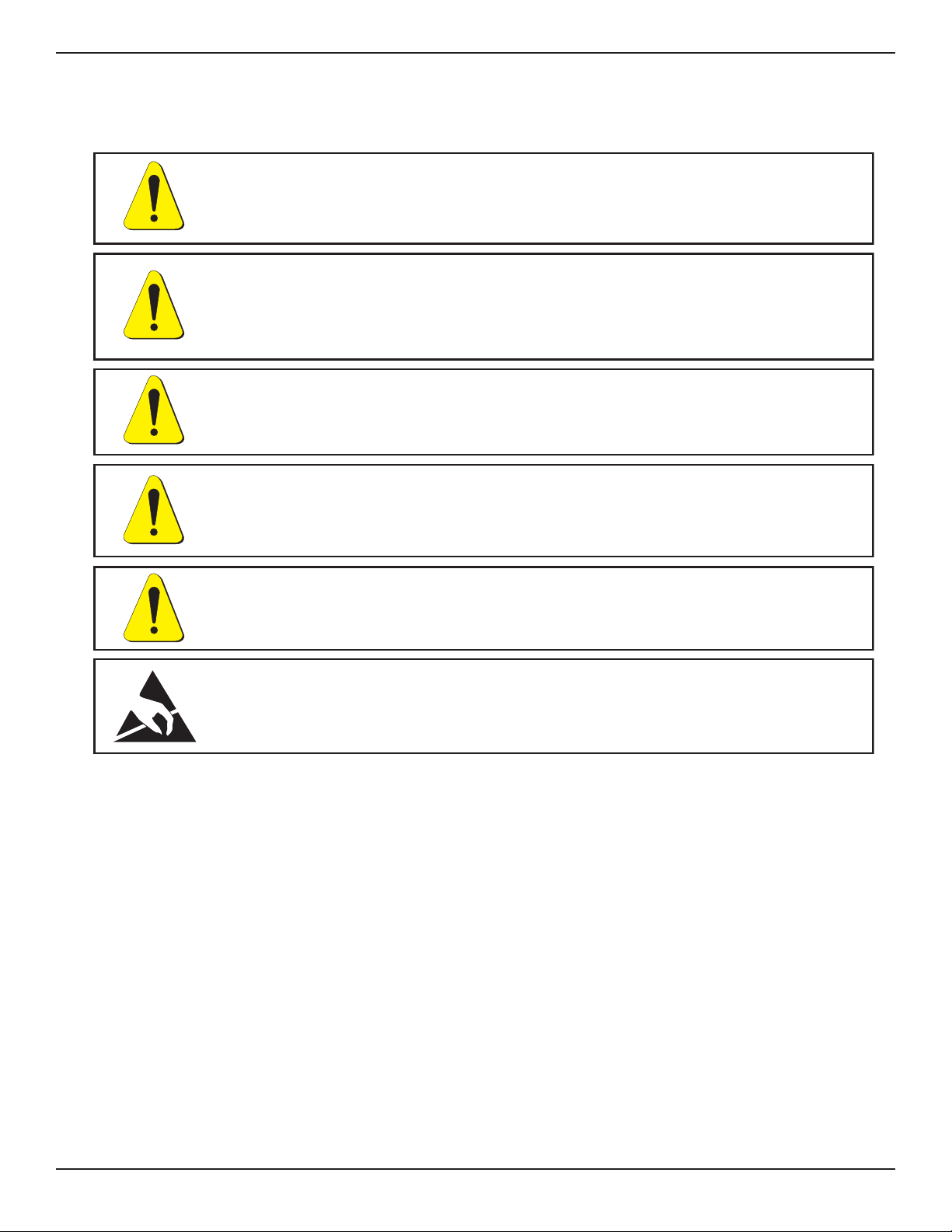
WARNINGS AND CAUTION NOTES
IMPORTANT NOTE
Please Notice: The product specifications and other information contained in this manual are subject to
change without notice. Mensor Corporation has made a concerted effort to provide complete and current
information for the proper use of the equipment. If there are questions regarding this manual or the proper
use of the equipment, contact Mensor Corporation at:
TEL 1.512.396.4200 or 1.800.984.4200 (USA only)
FAX 1.512.396.1820
WEB SITE http://www.mensor.com
E-MAIL [email protected]
CAUTION: USE THE PROPER PRESSURE MEDIUM. USE ONLY CLEAN,
DRY NON-CORROSIVE GASES. THIS INSTRUMENT IS NOT DESIGNED
FOR OXYGEN USE.
WARNING: NOT EXPLOSION PROOF!
Installation of this instrument in an area requiring devices rated as intrinsically
safe is not recommended.
WARNING: POSSIBLE INJURY!
The tubing, valves and other apparatus attached to the gauge must be adequate
for the maximum pressure which will be applied, otherwise physical injury to the
operator or bystanders is possible.
WARNING: HIGH SOUND LEVELS!
Pressures from 600 psig and up can generate sound levels above 100 db for brief
periods when they are exhausted directly to atmosphere. If no muffling devices are
attached to the EXHAUST port, then ear protection is advised for personnel in
the vicinity of instruments that will be operated under such conditions.
WARNING: HIGH PRESSURE!
High pressure gases are potentially hazardous. Energy stored in these gases can be
released suddenly and with extreme force. High pressure systems should be assembled
and operated only by personnel who have been trained in proper safety practices.
CAUTION: ESD PROTECTION REQUIRED. The proper use of grounded
work surfaces and personal wrist straps are required when coming into contact
with exposed circuits (printed circuit boards) to prevent static discharge to
sensitive electronic components.
PCS 400 PREFACE
www.mensor.com iii

PACKAGING FOR SHIPMENT
If the product must be shipped to a different location or returned to Mensor for any reason through a
common carrier it must be packaged properly to minimize the risk of damage.
The recommended method of packing is to place the instrument in a container, surrounded on all sides
with at least four inches of shock attenuation material such as styrofoam peanuts.
SOFTWARE LICENSE AGREEMENT
This product contains intellectual property, i.e., software programs, that are licensed for use by the end
user/customer (hereinafter “end user”).
This is not a sale of such intellectual property.
The end user shall not copy, disassemble or reverse compile the software program.
THE SOFTWARE PROGRAMS ARE PROVIDED TO THE END USER “AS IS” WITHOUT WARRANTY OF
ANY KIND, EITHER EXPRESS OR IMPLIED, INCLUDING, BUT NOT LIMITED TO, WARRANTIES OF
MERCHANTABILITY AND FITNESS FOR A PARTICULAR PURPOSE. THE ENTIRE RISK OF THE
QUALITY AND PERFORMANCE OF THE SOFTWARE PROGRAM IS WITH THE END USER.
MENSOR AND ITS SUPPLIERS SHALL NOT BE HELD TO ANY LIABILITY FOR ANY DAMAGES
SUFFERED OR INCURRED BY THE END USER (INCLUDING, BUT NOT LIMITED TO, GENERAL,
SPECIAL, CONSEQUENTIAL OR INCIDENTAL DAMAGES INCLUDING DAMAGES FOR LOSS OF BUSI-
NESS PROFITS, BUSINESS INTERRUPTION, LOSS OF BUSINESS INFORMATION AND THE LIKE),
ARISING FROM OR IN CONNECTION WITH THE DELIVERY, USE OR PERFORMANCE OF THE
SOFTWARE PROGRAM.
FCC RADIO FREQUENCY EMISSION NOTICE
This equipment has been tested and found to comply with the limits for a Class A digital device, pursuant
to Part 15 of the FCC Rules. These limits are designed to provide reasonable protection against harmful
interference when the equipment is operated in a commercial environment. This equipment generates,
uses, and can radiate radio frequency energy and, if not installed and used in accordance with the
instruction manual, may cause harmful interference to radio communications. Operation of this equipment
in a residential area is likely to cause harmful interference in which case the user will be required to correct
the interference at his or her own expense.
USE SHIELDED CABLES TO CONNECT EXTERNAL DEVICES TO THIS INSTRUMENT TO MINIMIZE
RF RADIATION.
TRADEMARKS
Mensor is a registered trademark of Mensor Corporation. All other brand and product names are
trademarks or registered trademarks of their respective companies. The PCS 400 instrument contains
software licensed from Microsoft Corporation.
©2005, Mensor Corp. All rights reserved.
PREFACE PCS 400
iv www.mensor.com

MENSOR BACKGROUND
HISTORY: Mensor is an ISO-9001:2000 certified manufacturer of precision pressure products. Mensor
was established in 1969 in Houston, Texas as an independent spin-off from the Texas Instruments (TI)
Pressure Instrument Group. As a private corporation, Mensor’s objective was to design and produce high
accuracy, high quality, easy to use pressure instruments. In 1978 Mensor moved to its present location in
San Marcos, on Interstate 35 (the Austin-San Antonio corridor). Two and a half years after the move, the
plant was destroyed by fire on Friday, February 13, 1981. Mensor resolved to come back, and almost
before the ashes had cooled, construction of a new building began on the same site. Six months after the
disaster, Mensor moved into its present facility and began shipping products to customers who had waited
patiently for the recovery.
PEOPLE: The key to Mensor’s strength in the marketplace is the concentration of experienced people in
the field of precision pressure measurement and control. The company’s founders previously worked in
various capacities in the Pressure Instrument Group of Texas Instruments, including engineering,
production and marketing. These founders were involved in the design of the original quartz bourdon
pressure gauge at TI. Mensor’s CEO, Jerry Fruit, is co-holder of the patent on using a fused quartz bourdon
tube to accurately measure pressure. Mensor employees have an average tenure of sixteen years. That’s a
lot of pressure experience!
PRODUCTS: Mensor’s portfolio of products consists of an extensive line of precision pressure instru-
ments, including digital gauges, pressure controllers, transducers and pressure calibrations systems. All
of these products feature computer interface capability. These products are used in metrology labs,
calibration labs, research facilities, engineering offices, production test stands, and in other environments
were high accuracy pressure measurement and/or control is required. Many of these products include
customized features to meet a customer’s specific requirement. Mensor products range from about $900
to $30,000.
CUSTOMERS: Typical Mensor customers are pressure sensor manufacturers, aerospace firms, jet engine
manufacturers, electric utilities, nuclear power plants, pharmaceutical firms, calibration laboratories,
government agencies and research organizations.
APPLICATIONS: In many facilities the highest accuracy pressure measuring or pressure controlling
instrument is a Mensor product. A typical application for these Mensor instruments is the calibration of
other pressure devices, such as sensors, transducers, transmitters, gauges and pressure switches. The
Mensor product is used as the pressure standard to verify pressure calibrations or outputs of the device
being produced, checked, tested or certified.
PCS 400 PREFACE
www.mensor.com v

SUMMARY OF CONTENTS
This manual includes the sections listed below.
1INTRODUCTION lists the items that are shipped with a standard instrument, provides
a brief overview of the instrument, and gives advice on an initial power-up.
2INSTALLATION states the mounting options, defines the pressure connections, and
gives examples of the initialization screens
3LOCAL OPERATION is a walk-thru of the display, keypads, transducers, modes of
operation and includes a complete menu tree.
4REMOTE OPERATION explains communicating with an external computer; includes
the commands available over the IEEE-488-STD bus, or via the RS-232 serial port.
5MAINTENANCE shows how to resolve some commonly encountered functional ques-
tions, and contains a list of available spare parts.
6CALIBRATION defines the recommended calibration intervals. Provides separate pro-
cedures for calibrating either absolute or gauge type instruments.
7SPECIFICATIONS lists the specifications for a standard instrument. Special or optional
features may include overriding specifications either in Section 8, Options,orasan
addendum to this manual.
8OPTIONS includes a functional description of the various options available as of this
printing. Also includes additional specifications and remote commands for some of these
options.
9APPENDIX contains a number of useful tables, figures, pneumatic schematics and
additional information.
10 INDEX lists keywords arranged alphabetically and provides text locations.
Rear Cover Pocket
This pocket holds a fold-out Menu Tree and a Quick Reference Card containing several
items of useful information.
At our web site you will find information and specifications on Mensor’s products
and services. From there you can ask questions, or direct comments to our sales
or technical people. Also available are various technical papers relating to pressure
management which you can browse, download or convert to hard copy.
MENSOR IS ON THE WEB AT www.mensor.com
PREFACE PCS 400
vi www.mensor.com

TABLE OF CONTENTS
Warranty ............................................. ii
Warnings and Caution Notes ...................................iii
Important Note ..........................................iii
Packaging for Shipment ......................................iv
Software License Agreement ...................................iv
FCC Radio Frequency Emission Notice ..............................iv
Trademarks ............................................iv
Mensor Background ........................................ v
Summary of Contents .......................................vi
INTRODUCTION
Did you get Everything? ..................................... 1-1
Initial Inspection ........................................ 1-1
Meet your Model PCS 400 .................................... 1-1
Front Panel ........................................ 1-1
Rear Panel ......................................... 1-2
Electrical Module ..................................... 1-2
Pneumatic Module ..................................... 1-3
Chassis Assembly ..................................... 1-4
Summary of PCS 400 Functions ................................. 1-5
Power Up! ............................................ 1-6
Mensor Service Plus ....................................... 1-6
Calibration Services ....................................... 1-6
Accreditations .......................................... 1-6
PCS 400 Evolution ........................................ 1-6
INSTALLATION
Mounting ............................................ 2-1
Pressure Connections ...................................... 2-1
SUPPLY Pressure Port ................................... 2-1
EXHAUST Pressure Port .................................. 2-1
MEASURE/CONTROL Pressure Port ........................... 2-1
REFERENCE Pressure Port ................................ 2-1
Power On ............................................ 2-2
System Checkout ........................................ 2-2
Control Pressure Check .................................. 2-2
System Leak Check .................................... 2-2
LOCAL OPERATION
Display ............................................. 3-1
Keypad ............................................. 3-1
Numeric Entry ....................................... 3-1
Mode Entry ........................................ 3-1
Menu Operations ..................................... 3-2
Mode Functions ...................................... 3-2
Default Values .......................................... 3-7
Transducer ........................................... 3-7
Address .......................................... 3-7
Active Transducer ..................................... 3-8
MEASURE Mode ........................................ 3-8
PCS 400 TABLE OF CONTENTS
www.mensor.com vii

Autorange ......................................... 3-8
Control Modes ......................................... 3-9
NORMAL Mode ...................................... 3-9
RATE Mode ........................................ 3-9
Multiple Internal Transducers ............................... 3-9
Setup for Control Mode ................................. 3-10
Input a Control Point Value ............................... 3-10
Incrementing the Control Point ............................. 3-10
Regulator Response ................................... 3-10
Optional Control Modes .................................... 3-10
Solenoid Valves Test ..................................... 3-11
Manual Valves Test ...................................... 3-11
Sequences ........................................... 3-11
Operation ........................................ 3-11
Create/Delete Sequence ................................. 3-12
List/Edit Sequence .................................... 3-14
List Mode ...................................... 3-14
Edit Mode ..................................... 3-14
Run Sequence ...................................... 3-15
Dual Passwords ..................................... 3-15
PCS 400 Menu Tree ...................................... 3-17
REMOTE OPERATION
Device Dependent Messages ................................ 4-1
IEEE-488-STD (GPIB) ..................................... 4-1
IEEE Capability Codes ................................... 4-1
Device Address ...................................... 4-1
Termination String Character ............................... 4-1
Service Request ...................................... 4-1
Local Lockout ....................................... 4-1
Status Display ....................................... 4-1
GPIB Interface Messages .................................. 4-1
DCL.......................................... 4-2
GET ......................................... 4-2
GTL ......................................... 4-2
IFC .......................................... 4-2
LLO.......................................... 4-2
SDC ......................................... 4-2
SRQ......................................... 4-2
Serial Poll ...................................... 4-2
PCS 400 Command Set ................................... 4-2
Definitions ...................................... 4-2
Commands ...................................... 4-3
Tests ......................................... 4-4
Queries ........................................ 4-5
PCS 400 Command Responses ................................. 4-7
Error Codes ........................................ 4-8
PCS 200 Emulation ................................... 4-10
Command Set ................................... 4-10
Emulation Responses ............................... 4-11
Command Reference ................................ 4-12
Changing the Mode of Operations ......................... 4-12
RS-232 Serial Communication ................................ 4-16
Cable Requirements ................................... 4-16
Setup .......................................... 4-16
TABLE OF CONTENTS PCS 400
viii www.mensor.com

Parameters ..................................... 4-16
Command Format ................................. 4-17
Command Examples ................................ 4-17
Single and Multi-Drop Cable Illustrations ..................... 4-18
MAINTENANCE
Beyond the Warranty ...................................... 5-1
Program Disk Replacement ................................... 5-1
Module Replacement ...................................... 5-1
Electrical Module ........................................ 5-1
Troubleshooting Guide ..................................... 5-2
Error Symptoms and Solutions .............................. 5-3
Spare Parts List ......................................... 5-6
CALIBRATION
Calibration Environment .................................... 6-1
Pressure Standard ....................................... 6-1
Calibration Medium ....................................... 6-1
Calibration Procedures ..................................... 6-1
Calibrating a Gauge Pressure Instrument ............................ 6-2
Calibrating the A/D ..................................... 6-2
Setting the Sensor Zero .................................. 6-2
Setting the Sensor Span .................................. 6-2
Calibrating an Absolute Pressure Instrument .......................... 6-3
Calibrating the A/D ..................................... 6-3
Setting the Sensor Zero .................................. 6-3
Setting the Sensor Span .................................. 6-4
SPECIFICATIONS
Measure Specifications ..................................... 7-1
Control Specifications ...................................... 7-2
General Specifications ..................................... 7-3
OPTIONS
1 - Rack Mount Kit ....................................... 8-2
2 - Transport Case ....................................... 8-4
3 - Multiple Range Pneumatics Kit ............................... 8-5
3a - Barometric Reference Transducer .......................... 8-5
3b - Two Independent Internal Transducers ........................ 8-5
4 - High Pressure Control Unit ................................. 8-7
5 - TI/Heise/Mensor Model 179 Controller Emulation ...................... 8-7
6 - Vacuum Gauge and Tube .................................. 8-7
7 - Bi-Directional Pressure Control ............................... 8-9
8 - Pressure Emulation Modes ................................. 8-9
8a - Gauge Transducers (Absolute Emulation) without BRT ............... 8-10
8b - Gauge Transducers (Absolute and Vacuum Emulation) with BRT ......... 8-10
8c - Absolute Transducers (Gauge Emulation) with BRT ................ 8-11
9 - External Analog Input ................................... 8-11
10 - Large Volume ....................................... 8-12
11 - BCD Output ....................................... 8-14
12 - Two’s Complement Binary Output ............................ 8-16
PCS 400 TABLE OF CONTENTS
www.mensor.com ix

13 - Servo-Disable ....................................... 8-18
14 - External Measure Mode Switch .............................. 8-18
15 - Measure Mode Signal ................................... 8-18
16 - Low Pressure External Plumbing ............................. 8-19
APPENDIX
Measurement Units - Unitno (Table 9.1) ............................ 9-1
Conversion Factors, PSI (Table 9.2) ............................... 9-2
Conversion Factors, Pascal (Table 9.3) ............................. 9-3
Temperature Conversion (Table 9.4) .............................. 9-4
Solenoid Valve Truth Table (Table 9.5) ............................. 9-5
Head Pressure Correction .................................... 9-6
Gas Density (Table 9.6) .................................. 9-6
Liquid Density (Table 9.7) ................................. 9-6
Head Pressure Calculation (Figure 9.1) .......................... 9-7
Sample Program ........................................ 9-8
Common Remote Commands Quick Reference (Table 9.8) .................. 9-10
Pneumatic Schem - Standard PCS 400 (Figure 9.2) ...................... 9-11
Pneumatic Schem - Dual Range PCS 400 (Figure 9.3) ..................... 9-12
Pneumatic Schem - Dual Range Press w/Baro Ref Transducer (Figure 9.4) .......... 9-13
Pneumatic Schem - Dual Abs Press w/Baro Ref Transducer (Figure 9.5) ........... 9-14
Pneumatic Schem - Two Independent Transducers (Figure 9.6) ............... 9-15
PCS 400 Sequence Program Script .............................. 9-16
INDEX ........................................... 10-1
REFERENCE LIST OF FIGURES AND TABLES
Figures:
Figure 1.1 – Front Panel .................................. 1-1
Figure 1.2 – PCS 400 Rear View .............................. 1-2
Figure 1.3 – Internal Electrical Module-Top View ..................... 1-2
Figure 1.4 – Pneumatic Module-Top View ......................... 1-3
Figure 1.5 – Chassis Assy-Top View ............................ 1-4
Figure 3.1 – Keypad .................................... 3-1
Figure 3.2 – PCS 400 Menu Tree ............................. 3-17
Figure 4.1 – Single Drop Cable ............................. 4-18
Figure 4.2 – Multi-Drop Cable .............................. 4-18
Figure 5.1 – Chassis Assy-Top View ............................ 5-2
Figure 6.1 – Calibration Setup-Gauge Pressure ...................... 6-2
Figure 6.2 – Calibration Setup-Absolute Pressure ..................... 6-3
Figure 7.1 – Dimensional Outline ............................. 7-3
Figure 8.1 – Rack Mount Dimensions ........................... 8-2
Figure 8.2 – Rack Specifications .............................. 8-3
Figure 8.3 – Slide Specifications .............................. 8-3
Figure 8.4 – Transport Case ................................ 8-4
Figure 8.5 – High Pressure Control Unit .......................... 8-7
Figure 8.6 – Rear Panel Vacuum Gauge Connector .................... 8-8
Figure 8.7 – VT-6 Gauge Tube Wiring ........................... 8-8
Figure 8.8 – Large Volume Option (<1000 cc’s external) ................ 8-13
Figure 8.9 – Large Volume Option (>1000 cc’s external) ................ 8-13
Figure 8.10 – BCD Output/Analog Input Connector ................... 8-15
TABLE OF CONTENTS PCS 400
x www.mensor.com

Figure 8.11 – Two’s Complement Binary Output .................... 8-17
Figure 8.12 – PCS 400 Rear View ............................. 8-18
Figure 8.13 – Pneumatic Connections for Low Pressure ................. 8-19
Figure 8.14 – Pneumatic Module for Low Pressure ................... 8-20
Figure 9.1 – Head Pressure Calculation .......................... 9-7
Figure 9.2 – Pneumatic Schematic-Standard PCS 400 .................. 9-11
Figure 9.3 – Pneumatic Schematic-Dual Range PCS 400 ................. 9-12
Figure 9.4 – Pneumatic Schematic-Dual Gauge Pressure with Baro Ref Transducer . . 9-13
Figure 9.5 – Pneumatic Schematic-Dual Absolute Pressure with Baro Ref Transducer . 9-14
Figure 9.6 – Pneumatic Schematic-Two Independent Transducers ........... 9-15
Tables:
Table 3.1 – Default Values ................................. 3-7
Table 3.2 – Min/Max Rate ................................. 3-9
Table 4.1 – Valid Output Format ............................. 4-7
Table 4.2 – Error Codes ............................... 4-8-4-9
Table 4.3 – Emulation Responses ............................ 4-11
Table 4.4 – Data Bits Format .............................. 4-16
Table 5.1 – Error Symptoms and Solutions ..................... 5-3-5-5
Table 5.2 – Spare Parts .................................. 5-6
Table 7.1 – Minimum/Maximum Slew Speed ....................... 7-2
Table 8.1 – Effects of mode switching (Gauge Transducer) ............... 8-10
Table 8.2 – Effects of mode switching (Absolute Transducer) .............. 8-10
Table 8.3 – Characters for Display Resolution ...................... 8-16
Table 9.1 – Measurement Units (unitno) .......................... 9-1
Table 9.2 – Conversion Factors, PSI ............................ 9-2
Table 9.3 – Conversion Factors, Pascal .......................... 9-3
Table 9.4 – Temperature Conversion Chart ........................ 9-4
Table 9.5 – Solenoid Valve Truth Table .......................... 9-5
Table 9.6 – Gas Density .................................. 9-6
Table 9.7 – Liquid Density ................................. 9-6
Table 9.8 – Quick Reference List of Common Remote Commands ........... 9-10
PCS 400 TABLE OF CONTENTS
www.mensor.com xi

U
ser
'
s
N
otes:
TABLE OF CONTENTS PCS 400
xii www.mensor.com
INTRODUCTION
DID YOU GET EVERYTHING?
In addition to this manual you should have:
·PCS 400
·Power cord
·Four 1/8 inch NPT fitting adapters
·Any accessories ordered
·An envelope containing a Calibration
Certificate
INITIAL INSPECTION
Your new Mensor instrument was thoroughly
tested and inspected at the factory, and it was free
of dings, dents and scratches when it was packaged
for shipment. Please examine it now for signs of
shipping damage. Report any apparent damage to
the carrier immediately.
MEET YOUR MODEL PCS 400
The Model PCS 400 Pressure Calibration System is
a self-contained, computerized, high accuracy
pressure management system integrated into a
single, compact unit. The system is comprised of a
front panel assembly, a rear panel, an electrical
module, a pneumatic module, and a chassis to tie
it all together. The system functions either as a
bench-top or a rack mounted instrument. It can
operate in local mode to accept front panel input,
or in remote mode to communicate with external
devices. A brief description of the major elements
of the system follows.
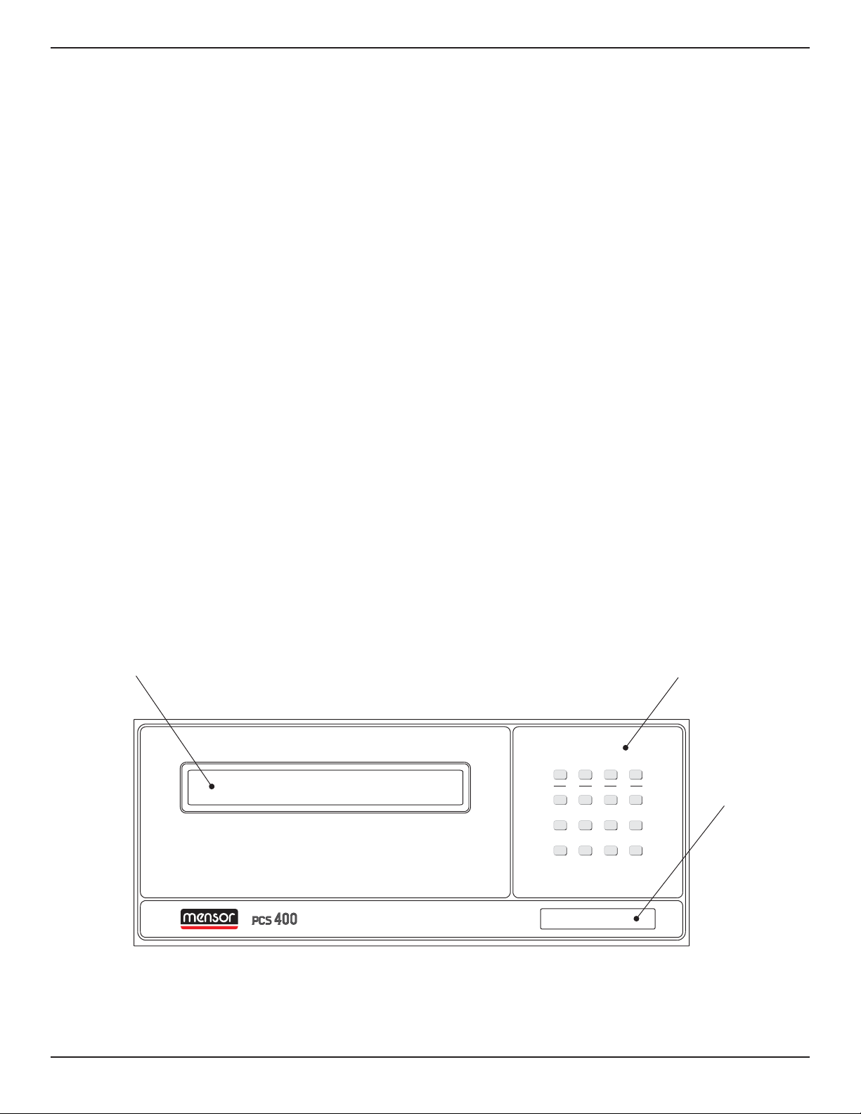
Front Panel
The front panel (figure 1.1) includes a forty char-
acter per line, two line display, a four by four
membrane keypad, and a transparent window for
the pressure range label. The keypad includes
fifteen dual-function keys, plus a sixteenth key,
labeled 2nd, which toggles the function of the other
fifteen. All sixteen keys provide both tactile and
audible feedback.
Keypad
Display
Pressure
Range
0-600 PSIA
2nd
F1 F2 F3
1
0
=
5
_
3
.
7
2
9
6
4
+
8CE
METRIC ENG GPIB SERIAL
CAL TEST LIMITS HELP
STBY CONT VENTMEAS
UNITS COMM
PRESSURE CALIBRATION SYSTEM
Figure 1.1 - Front Panel
PCS 400 INTRODUCTION
www.mensor.com 1-1

Rear Panel
The rear panel (figure 1.2) includes access to the
line-fuse holder, the power cord socket, the system
power switch, a ventilator fan opening, and several
communication connectors. All of these items are
grouped on the electrical module side of the rear
Electrical Module
The internal electrical module (figure 1.3, shown
with its cover removed) is self contained and can
be replaced as a unit. It consists of the input power
module, a fan, a power supply, a computer assem-
bly, a 3.5 inch disk drive and a flash disk.
panel. The pneumatic side exposes the four fitting
ports of the pressure manifold, and may have ad-
ditional electrical connectors to support optional
functions.
Input Power
Module
Power Supply/
Fan
Disk Drive
Backplane
CPU BOARD
GPIB
PRINTER DRIVER
SOLENOID DRIVER
PLA
Figure 1.3 - Top View of Internal Electrical Module
Power
Switch
Power
Connector
Line
Fuses
Communication
Ports
Pressure
Ports
MEASURE/
CONTROL
REFERENCE EXHAUST SUPPLY
IEEE STD 488 PORT
SH1, AH1, T6, L4,
SR1, RL1, PP0,
DC1, DT1, E2, C0
SERIAL PORT
FUSE: 250V/1.5A
“This equipment complies with the requirements in
Part 15 of FCC Rules for a Class A computing device.
Operation of this equipment in a residential area may
cause unacceptable interference to radio and TV
reception requiring the operator to take whatever
steps are necessary to correct the interference.”
Optional Connectors
as required
Figure 1.2 - Rear View
The drive is accessible by removing the rear panel
which is attached by seven screws. Note that the
plug-in printed circuit cards are not necessarily in
the order illustrated.
INTRODUCTION PCS 400
1-2 www.mensor.com

Pneumatic Module
The pneumatic module (figure 1.4) includes a pri-
mary Silicon Pressure Transducer (SPT) consist-
ing of a sensor inside a rugged aluminum housing,
and three piggy-backed circuit board assemblies
mounted to the outside. These boards contain the
signal conditioning and calibration constants for
the SPT. The pneumatic module also includes a
Reed Valve Regulator (RVR) pressure controller, an
auxiliary transducer, a manifold, and all of the
interconnecting plumbing. The pneumatic module
also has the cables required to connect it to the
electrical module. In addition, this module may
include as options, one or two additional
transducers (3 SPTs maximum), shown at address
#01 and #02.
The electrical and pneumatic modules are each
self-contained and can be replaced individually.
System accuracy is maintained when any compo-
nent is replaced because the transducer’s calibra-
tion data resides on the transducers.
The only moving parts in the PCS 400 are the fan,
the disk drive mechanism, the pneumatic flow
controller diaphragms and valves, and the solenoid
valve plungers. There are no internal user adjust-
ments or setup switches.
Shown configured with three SPTs (maximum)
Manifold
Regulator Auxiliary
Transducer
L1
L2
L3
L4
L5
L6
S
PT #01
Secondary
(Optional)
SPT #02
Baro Ref
(
O
p
tional
)
SPT #00
(Primary)
Figure 1.4 - Top View of Pneumatic Module
PCS 400 INTRODUCTION
www.mensor.com 1-3

Chassis Assembly
The chassis assembly acts as the housing for the system. Each of the major components is easily removed
and replaced using basic hand tools. The layout of the internal system is illustrated in the figure below.
Front
Rear
Electrical
Module
Interior
(shown with the
cover removed)
Pneumatic
Module
Figure 1.5 - Top View of Chassis Assembly
INTRODUCTION PCS 400
1-4 www.mensor.com

SUMMARY OF PCS 400 FUNCTIONS
Below is a list giving a brief description of the various functions available to the PCS 400. This listing begins
with descriptions of the three function keys on the bottom row, progresses from [1] through [9] in numerical
order, then ends with [CE], [+] and [-]. The listing begins with the key cap inscription shown in brackets,
followed by the mode legend for the key in capital letters, and finally a sentence or so of descriptive text.
Detailed explanations for all of the functions, and how to access them, are provided in Section 3, Local
Operation. Additional information can also be found in Section 4, Remote Operation.
KEY FUNCTION DESCRIPTION
[0] F1 Function key F1 is used only with certain options.
[.] F2 Sequences: Macros which can be created, edited, run and deleted.
[=] F3 Function key F3 is used only with certain options.
[1] CALIBRATION Allows the user to calibrate transducers and some functions
of the instrument.
Sensor Zero Calibrate A/D Baro Cal
Sensor Span Calibrate Auxiliary Sensor Save Control Settings
[2] TEST Provides the means to quickly test various internal electrical and
pneumatic functions or components. (Does not apply to HPCU.)
All Tests Regulator Display Solenoid Valves
Sensor Internal Leak Keypad Program Memory
Source Pressure System Leak Program
[3] LIMITS Allows the operator to select certain items or functions and set
parameters.
Active Transducer Cont Stable Window & Delay Restore Defaults
Control Limits Press/Rate/Peak Chg Passwords
Filter Display Resolution
[4] METRIC Allows the user to convert pressure reading to the metric units
selected from a list. The selected units will be displayed with any
mode that displays pressure readings.
[5] ENGLISH Allows the user to convert pressure readings to selected English units.
[6] GPIB Provides a means to set up parameters for use with GPIB communi-
cations.
Address Termination Character
[7] STANDBY Places instrument in the “Standby Mode”. The last measured or
controlled pressure will be displayed.
[8] MEASURE Measures the pressure at the “Measure/Control” pressure port.
[9] CONTROL Generates a pressure in response to a command point set via the
keypad or a remote command.
PCS 400 INTRODUCTION
www.mensor.com 1-5

[CE] VENT Vents the “Measure/Control” pressure port to atmosphere.
[+] HELP Displays instrument name, software version, chassis serial
number and full scale range.
[–] SERIAL Provides a way to set the parameters to be used with RS-232
communications.
Address Termination Character Data Format
Baud Single/Multi Drop
[2nd] 2nd Toggles keypad between numeric and mode functions.
POWER UP!
You can confirm that your PCS 400 is operational
right now. Simply apply power to the power con-
nector on the rear of the instrument, remove any
plastic plugs from the PRESSURE and REFER-
ENCE ports and turn the power switch ON. When
the PCS 400 is turned on it goes through an initiali-
zation process which includes scanning the inter-
nal configuration for file code errors.
About one minute after power is applied the full
display will come on. With no pressure connected,
an absolute instrument of sufficient range will dis-
play atmospheric pressure, while a gauge instru-
ment will display at or very near zero pressure. In
any case the pressure will be displayed in the
measurement units that were specified when the
instrument was ordered.
This confirms that the unit is ready to use. If this
is your first time to use a PCS 400 please review the
Warnings and Cautions information inside the
front cover. Then take the time to familiarize your-
self with the Installation and Operation sections of
this manual and the ‘Menu Tree’ provided there. Te
tree illustrates the command structure and the
functions available from the front panel keypad.
MENSOR SERVICE PLUS
If you have problems using your PCS 400 and you
don’t find the answer in your manual, contact
Mensor at 1.800.984.4200 (USA only), or
1.512.396.4200 for personal assistance, or at any
of the on-line addresses listed in the front of the
manual. We are ready to help.
Mensor’s concern with the welfare of this instru-
ment is not limited to the warranty period. We
provide complete repair services beyond the war-
ranty, as explained in Section 5, Maintenance.
CALIBRATION SERVICES
In addition to servicing our own products Mensor
can perform a complete pressure calibration serv-
ice, up to 20,000 psi, for all of your pressure
instruments. This service includes a Calibration
Certificate and a record of traceability to the pres-
sure standards of the National Institute of Stand-
ards and Technology (NIST).
ACCREDITATIONS
MensorCorp.isregisteredtoBSENISO
9001:2000. The calibration program at Mensor is
accredited by A2LA, as complying with both the
ISO/IEC FDIS 17025:1999 and the ANSI/NCSL
Z540-1-1994 standards.
PCS 400 EVOLUTION
Since its introduction in the PCS 400 has undergone
a continuous process of evolution. Many changes
have been in response to special application re-
quirements expressed by our customers. Once they
are designed these ‘specials’ are either incorpo-
rated into the standard system, or made available
as options to other users with similar require-
ments. All customers are welcome to discuss their
unique requirements. We may already have a solu-
tion, or we can provide one.The system has proven
to be extremely flexible in this way because of the
modularity of both the software and the hardware.
INTRODUCTION PCS 400
1-6 www.mensor.com

INSTALLATION
MOUNTING
The instrument can be set up on a table-top or it
can be rack-mounted. For rack-mount installation,
see the instructions in Section 8, Options.
The special sensor used in the PCS 400 is relatively
insensitive to tilt and vibration. However to further
assure stability and accuracy, excessive motor or
machinery vibration of the mounting surface
should be avoided.
PRESSURE CONNECTIONS
NOTE: When making up connections to
the o-ring adapter use a back-up wrench
to prevent over-stressing the threads in
the manifold block.
The pressure ports on the rear manifold block are
female 7/16 - 20 SAE/MS straight threads per
MS16142 and SAE J514 table 14. They require a
tube fitting boss seal with an o-ring per MS33656.
Mensor provides female 1/8 NPT adapter fittings
with the instrument. The pressure connection can
be made to these adapters with the proper mating
hardware. We recommend the use of either Loctite
Hydraulic Sealant or fresh teflon tape on the
threads of the male pipe fitting. Do not use sealants
on fittings sealed with an o-ring. The integrity of the
seal is particularly important since even micro-
scopic leaks can cause errors in measurements.
Figure 9.2 is a pneumatic schematic of the internal
plumbing (see figures 9.3 through 9.6 in the Appen-
dix for additional pneumatic schematics showing
optional configurations).
Table 9.5 in the Appendix shows the status of
solenoid valves L1 through L6 during different
operating conditions. Requirements for connecting
to the various ports on the PCS 400 manifold are
given below.
SUPPLY Pressure Port
Connect a pressure source to the SUPPLY port of
the PCS 400. This pressure will be used to derive
the CONTROL pressure output at the MEAS-
URE/CONTROL port. The supply pressure must be
greater than the highest control pressure that will
be commanded which is usually the full scale (FS)
range of the instrument.
EXHAUST Pressure Port
The EXHAUST pressure port is either left open to
atmosphere or connected to a vacuum pump in
order to control at pressures below atmospheric
pressure. A vacuum pump will also improve con-
trol for positive pressures below 0.25 psig.
MEASURE/CONTROL Pressure Port
The MEASURE/CONTROL port is a bi-directional
port. It can receive an unknown pressure to be
measured, or upon command it can output a con-
trolled pressure to external devices. In the MEAS-
URE mode, solenoid valve L5 is closed (see table
9.5, Solenoid Valve Truth Table, in the Appendix).
This isolates the regulator from the port but leaves
the measure path open to the transducer(s). In
CONTROL mode, L5 is opened to allow the regu-
lated pressure output to reach the same port.
For optimum CONTROL performance the external
system connected to this port should consist of a
total volume between 0.01 and 0.5 liters. External
volumes less than 0.01 liter will decrease control
stability, and volumes greater than 0.5 liter will
increase overshoot and control times.
REFERENCE Pressure Port
If an optional Barometric Reference Transducer
(BRT) is included in the PCS 400, the REFERENCE
port might be internally connected to its pressure
port. If there is no BRT then the REFERENCE port
is either connected to the reference port(s) of the
gauge pressure transducer(s), or internally plugged
on absolute units. Refer to the Appendix section of
the manual for the appropriate pneumatic sche-
matic diagram that applies to your instument.
CAUTION: HIGH NOISE LEVELS.
As pressure decreases compressed gas will
escape out the EXHAUST port. For ranges
above 600 psi high noise levels may result
during such pressure releases. To overcome
objectionable exhaust noise either install a
muffler or route the port to a remote
location.
PCS 400 INSTALLATION
www.mensor.com 2-1
Table of contents
Other mensor Test Equipment manuals


