mensor 9415 User manual
Mensor Model 9415 Multi-Channel Pressure Test System
Mensor LP, 201 Barnes Drive, San Marcos, TX, USA

Mensor Model 9415 Multi-Channel Pressure Test System Manual Rev. I
1
Table Of Contents:
Pg 1: Table of Contents
Pg 2: Blank
Pg 3: General Description
Pg 4: General Description
Pg 5: Warnings
Pg 6: Pneumatic Schematic
Setup
Pg 7: Brace Kit Breakdown
Pg 8: Bracing Installation
Pg 9: Tubing Installations Points
Pg 10: Electrical Connectors Installation Locations
Pg 11: Electrical Connectors
Location 1
Pg 12: Location 2
Pg 13: Location 3
Finishing Touches
Pg 14: Upgrade Section
Setup
Pg 15: Vacuum Port Fittings
Pg 16: Removing the Old Power Hub
Pg 17: Disconnect Switch Wiring Change
Pg 18: Electrical Kit Breakdown:
Pg 19: Grounding Rails Installation:
Pg 20: Disconnect Switch Cable Routing
Pg 21: Disconnect Switch Cable Routing
Pg 22: Vacuum Pump Cable Routing
Pg 23: Vacuum Pump Cable Routing
Pg 24: Model 9414 Grounding And Cable Routing
Pg 25: Grounding The 9415:
Pg 26: Tubing
End of Upgrade Section
Pg 27: Operation:
Operation of Model 9414
Pg 28: Operation of Model 9414
Pg 29: Communication Protocol:
Command Set
Pg 30: Normal operation
Normal Shutdown Sequence
Pg 31: Emergency Shutdown Sequence
Notes on Remote Transducers

Mensor Model 9415 Multi-Channel Pressure Test System Manual Rev. I
2
“Calibration” of Model 9414 Controller’s Pressure Measuring
Sensors:
Pg 32: “Calibration” of Model 9414 Controller’s Pressure Measuring
Sensors:
Pg 33: “Calibration” of Model 9414 Controller’s Pressure Measuring
Sensors:
Pg 34: Storage and Transportation:
Maintenance:
Pg 35: Maintenance:
Pg 36: General Specifications and Ratings:
Pg 37: General Specifications and Ratings:
Pg 38: Tables:
Pg 39: Tables:
Pg 40: Table 2:
Pg 41: Table 2:
Pg 42: Table 2:
Pg 43-58: Appendix A
Pg 58-60: Appendix B
Mensor Model 9415 Multi-Channel Pressure Test System Manual Rev. I
3
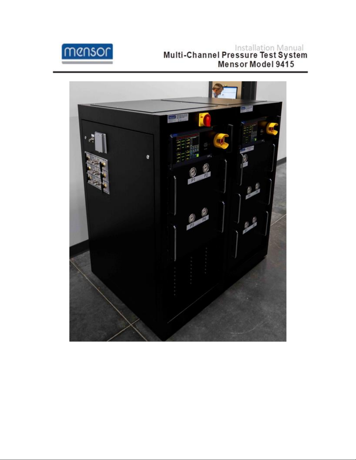
Mensor Model 9415
Multi-Channel Pressure Test System
General Description:
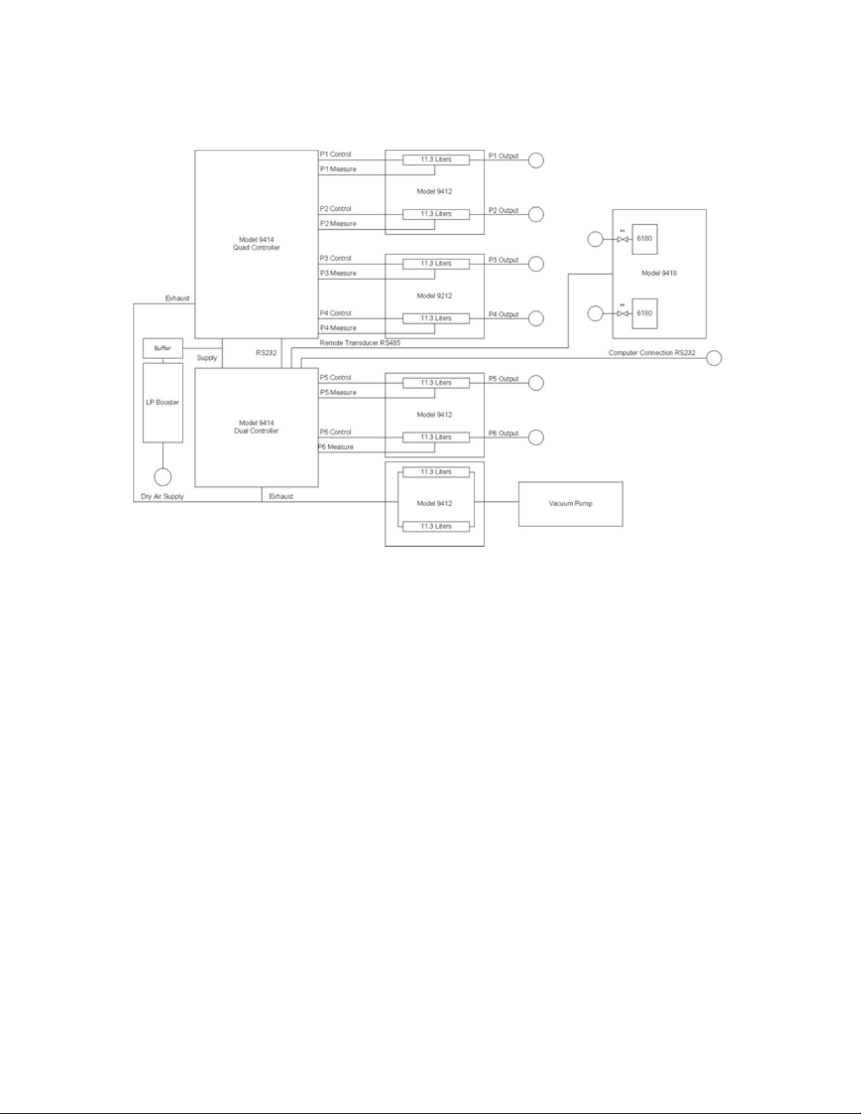
The Mensor Model 9415 Multi-Channel Pressure Test System is used for rapid
testing of pressure transducers. It can be a single or dual rack configured with
two, four, or six control channels. The model 9414 (quad or dual) controllers
provide the control channels. For each pair of control channels, there is a Model
9412 pressure tank. The maximum range of this system is 160 psi. Depending
on requirements, a system can be developed with a maximum operating
pressure of 1500 PSI. A Model 9418 Remote Transducer Module with up to four
Mensor CPT6180 remote transducers is used for measurements at the test
device and can have full-scale ranges of up to 160 psi (~11 bar). All internal
transducers have an accuracy of 0.010 % of full scale and a precision of 0.003 %
of full scale. Remote transducers can have accuracies of either 0.010 % of full
scale or 0.01% IS-50 (0.010 % of reading from mid to full scale and 0.005% of
full scale under 50 % of full scale). See General Specifications and Ratings
section near the end of the manual for sizes.
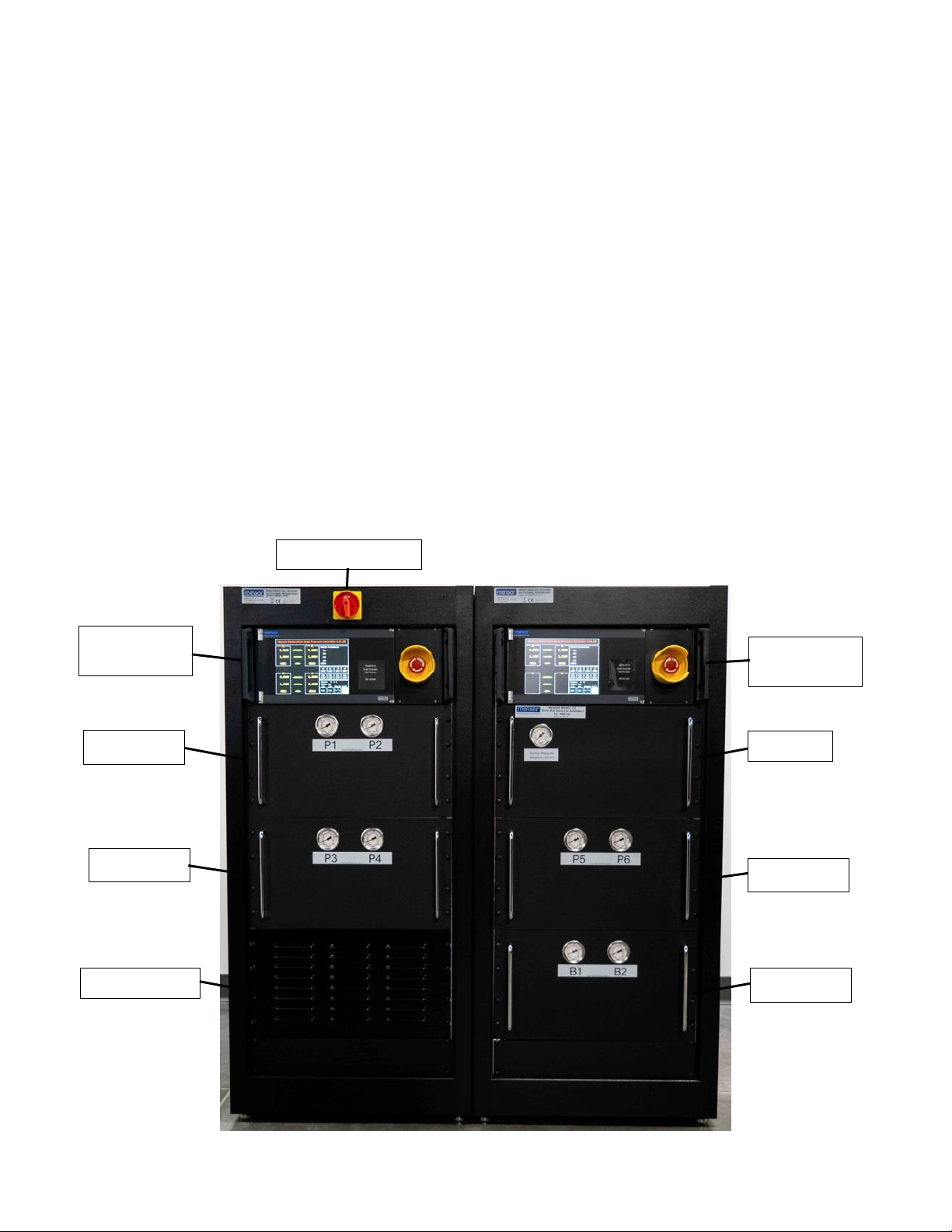
Model 9414
4-Channel
Model 9414
2-Channel
Model 9412
Model 9412
Model 9412
Model 9412
Vacuum Pump
Model 73
Disconnect Switch
Mensor Model 9415 Multi-Channel Pressure Test System Manual Rev. I
4
External pressure porting and electrical signal connection pass-thrus are
provided on the left side of the rack when viewed from the front. Pressure ports
include an input for shop air and either two or four output pressure connections to
connect to the Model 9418 Remote Transducer Module or directly to the device
handler (DUT). A cable access port provides entry to the rack for controlling and
reading the remote transducers in the Model 9418 Remote Transducer Module
(25 pin D-sub connector) and a 9 pin D-Sub connector for serial communications
between the rack and a host computer. Sufficient space is allowed for other user
cabling.
The rack will accept AC power (105 to 240 VAC, 47 to 63 Hz.)Power is brought
into the rack via a junction box at the bottom of the rack. The power cord plug on
the input to the rack can be replaced to accept other plugs or can be tied directly
into a main feed. The power cable used is rated for 15 amp service. The Model
9415 system has a power cut off switch located on the top of the left rack which
connects/disconnects the power to the rack’s “Electrical Junction Box”. This box
provides a constant AC power supply to the Model 9414 controllers and houses
electronics for the relay control of the vacuum pump’s AC power supply. The AC
power enters each Model 9414 through a fused and switched “Power Entry
Module” using a standard, NEMA, three-conductor plug. Internally to each Model
9414, the AC power goes directly from the “Power Entry Module” to the front-
mounted, “Emergency Stop” switch which disconnects the AC power going to the
Model 9414’s internal “Switching Power Supply” is rated for 100-240VAC at 47-
63Hz. The switched power is then utilized internally to generate +5 volt DC and
+12 volt DC to control the solenoid valves, electronics, and remote transducers.
The Model 9414 is fused on both the hot and neutral AC lines entering the unit.
The Mensor 6180 transducer(s) in the
remote transducer module (Model
9418) utilize RS-485 for
communications with the Model 9414
Quad Pressure Controller(s). Control
of the isolation solenoids (if equipped)
is done internally in the 9414
controller and provided to the Remote
Transducer Module through the same
25 pin D-sub connector as the RS-
485 communications. The RS-485
port communicates with the remote
transducers at 19200 Baud with 8
data bits, 1 stop bit, and no parity.
Communications between the Model
9414 Dual Pressure Controller and
the user’s computer are on a 9 pin D-
Sub connector at 57,600 Baud, 8 data
bits, 1 stop bit, and no parity. See
Appendix A for a list of the command sets.
Mensor Model 9415 Multi-Channel Pressure Test System Manual Rev. I
5
Precautions:
The maximum working pressure of the system is 300psi (~20
bar), however, the limitation of the downstream equipment is
annotated on the controllers and needs to be adhered to
The system contains large pressure storage tanks that can
hold large amounts of kinetic energy. User should bleed all
pressure stored in the tanks before servicing, removing
pressure hoses, or removing instruments. Normal shutdown
and emergency shutdown should start the process, but due
to the size of the tanks, and desire to maintain a safe
discharge rate, this operation may take an extended period of
time to achieve. Utilize the pressure gauges on the front of
the 9412 Module to ensure pressure has been released from
each tank.
The system uses normal power line AC voltages. User
should remove the AC power cord from mains when
servicing inside enclosures.
Due to the internal pressures and voltages used within the
9415 system, only qualified and properly trained personnel
should service this system.
The emergency shutdown electrical system is limited in
capacity to approximately 6 amps of power. It is intended to
shut down the pressure portion of the system (Model 9414)
and slowly release pressure from the pressure tanks in the
Model 9412(s).
User should orient the system in a way that the Emergency
Shutoff Button, the power cord connection, and the pressure
valves on the side of the rack, if so equipped, should also be
accessible to the operator for rapid shutdown.
Special handling and carrying techniques are required as
some individual components in the system exceed 18 kg. A
“TWO MAN LIFT” should be employed.
Mensor Model 9415 Multi-Channel Pressure Test System Manual Rev. I
6
Pneumatic Schematic
Setup:
The initial installation should include removing any packing material used in
shipment and inspecting that fittings and screws are snug and that hoses and
electrical cords are not chaffed or cut. The system rack is mounted on casters
and should be installed on a level surface with adequate airflow to keep the
system within its 15 to 45 C optimum operating temperature range. The
emergency shutoff button on the 9414 controller, the rack power connection, and
the safety valves on the side of the rack, if so equipped, should be accessible to
the operator. Wheel chocks or threaded feet/supports should be used where
appropriate to keep the unit in place. The system operates on line voltages
between 105 and 240 VAC, 47 to 63 Hz. A dry, clean, compressed air or
nitrogen supply is required for operation.
The quad pressure output ports are located on the side of the rack and are
labeled P1, P2, P3, and P4 Outputs. If a dual channel system is ordered, only
P1 and P2 will be available. If a six-channel system is ordered, P5 and P6 will be
available. The fittings on the side panel are ¼” tube fittings. Sufficient ¼” flexible
tubing is provided to allow four 6 to 10 foot (~2 meters) pressure hoses to
connect between the rack and pressure selection valves in either the Model 9418
Remote Transducer Module or the handler.

Mensor Model 9415 Multi-Channel Pressure Test System Manual Rev. I
7
First, remove the side panels on the left and right side of the
rack with the main power disconnect switch. This is
accomplished by turning the fasteners on the side panel
and removing the panel. If a rear door is installed it should
be opened for easier access.
Then, using the supplied allen wrench, loosen the vacuum
pump’s shipping locks; the vacuum pump is located on the
bottom of the rack with the vented front panel. Refer to the
instruction package with the allen wrench for more details
on this step.
Reinstall the panel on the left side and leave the panel off on the right side.
Remove the left side panel of the other rack (the one without the main power
disconnect switch). If a rear door is installed, open that one as well. Proceed to
bolt the racks together using the braces provided.
Brace Kit Breakdown:
Brackets (2)
10-32 Screws (8)
Lock Washer (8)
Flat Washer (8)
Mensor Model 9415 Multi-Channel Pressure Test System Manual Rev. I
8
Bracing Installation:
The first bracket should be installed above the 20 rail indentation. Each screw
should have a lock washer followed by a flat washer which then contacts the
bracket.
20 Rail Indentation
2 Rail Indentation
10-32 Screw
Lock Washer
Flat Washer

Mensor Model 9415 Multi-Channel Pressure Test System Manual Rev. I
9
The next bracket should be installed above the 2 rail indentation. Each screw
should have a lock washer followed by a flat washer which then contacts the
bracket.
Tubing Installations Points:
Do not disconnect any tubing. All tubing that needs to be attached will have one
loose end. All loose ended tubing will be in the rack that doesn’t have the main
power disconnect.
Grab the vacuum line (3/8”
Yellow Tube) labeled
“Vacuum”coming off the B1
and B2Model 9412 and
connect it to the vacuum
pump port.
Grab the remaining vacuum
line (3/8” Yellow Tube)
labeled “P1 Exhaust”coming
off the 9414 Quad and
connect it to the port labeled
“Exhaust”on the P1 side of
the Model 9414 Quad.
Grab the air supply line (1/4”
Black Tube) labeled “P1
Supply”coming off the 2-
Channel Model 9414 supply
Tee and connect it to the port
labeled “Supply”. This port is
located on the P1 side of the
Model 9414 Quad.
Grab the air supply line (3/8”
Black Tube) labeled “Shop
Air”coming off the Model 73
and connect it to the rear of
the “Shop Air Input port
located on the I/O Port
Panel.
Grab the P5 output line (1/4”
Blue Tube) labeled “P5
Output”coming off the 9412
and connect it to the rear of
the “P5 Output Port”located on the I/O port panel.
Grab the P6 output line (1/4” White Tube) coming off the 9412 labeled “P6
Output”and connect it to the rear of the “P6 Output” located on the I/O
port panel.
Ensure that all tubing connections are secured tightly, to ensure an air tight seal,
before proceeding.

Mensor Model 9415 Multi-Channel Pressure Test System Manual Rev. I
10
Electrical Connectors Installation Locations:
There are three major electrical connectors that need to be plugged in and one
grounding wire that will need to be secured to the chassis grounding bus. Do not
unplug anything. All wiring that needs to be attached will have one loose end. All
loose ended wiring will be in the rack that doesn’t have the main power
disconnect. Ensure that the AC power cord is removed from any mains during all
electrical work.
Location 1
Location 2
Location 3
Mensor Model 9415 Multi-Channel Pressure Test System Manual Rev. I
11
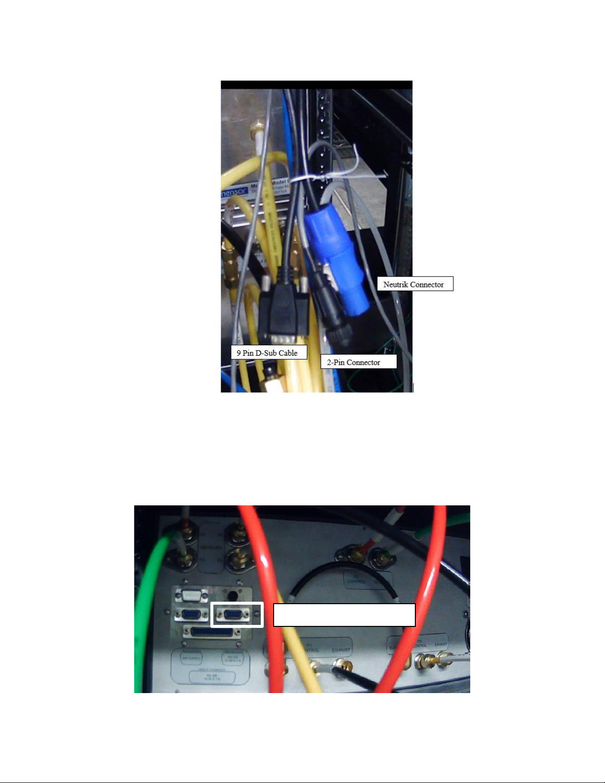
Electrical Connectors:
The “Neutrik Connector” is responsible for providing AC power to the 4-
Channel Model 9414.
The “2-Pin Connector” signals the vacuum pump to turn on/off.
The “9 Pin D-Sub Cable” is responsible for communication between the
two Models 9414.
Location 1:
Insert and secure the “9 pin D-Sub Cable”into the back of the Model
9414.
9 Pin D-Sub Cable Connection

Mensor Model 9415 Multi-Channel Pressure Test System Manual Rev. I
12
Location 2:
Insert the black “2-Pin Connector”into the black port labeled “Vacuum
Relay”. Be cognizant of the orientation of the connectors’ and sockets’
keying for correct polarity.
Insert the blue “Neutrik Connector”into the blue port label “Dual
Controller”. Ensure the connector is secured by inserting the connector,
rotating clockwise, and confirming that the metal slide lock is locked.
2-Pin Connector Connection
Neutrik Connector Connection

Mensor Model 9415 Multi-Channel Pressure Test System Manual Rev. I
13
Location 3:
There will be a loose green wire. The loose end of this wire should
be secured to the chassis grounding bus shown above. The ground
terminal will be located near the vacuum pump between the two
racks.
Finishing Touches:
Connect the existing model 9418 to
the back of the dual Model 9414’s
I/O electrical panel with the
provided cable (DB 25 M-F cable).
Connect a source of clean, “Shop
Air”, to the supply port on the I/O
port panel.
Connect the completed model
9415’s AC power cable to the
mains.
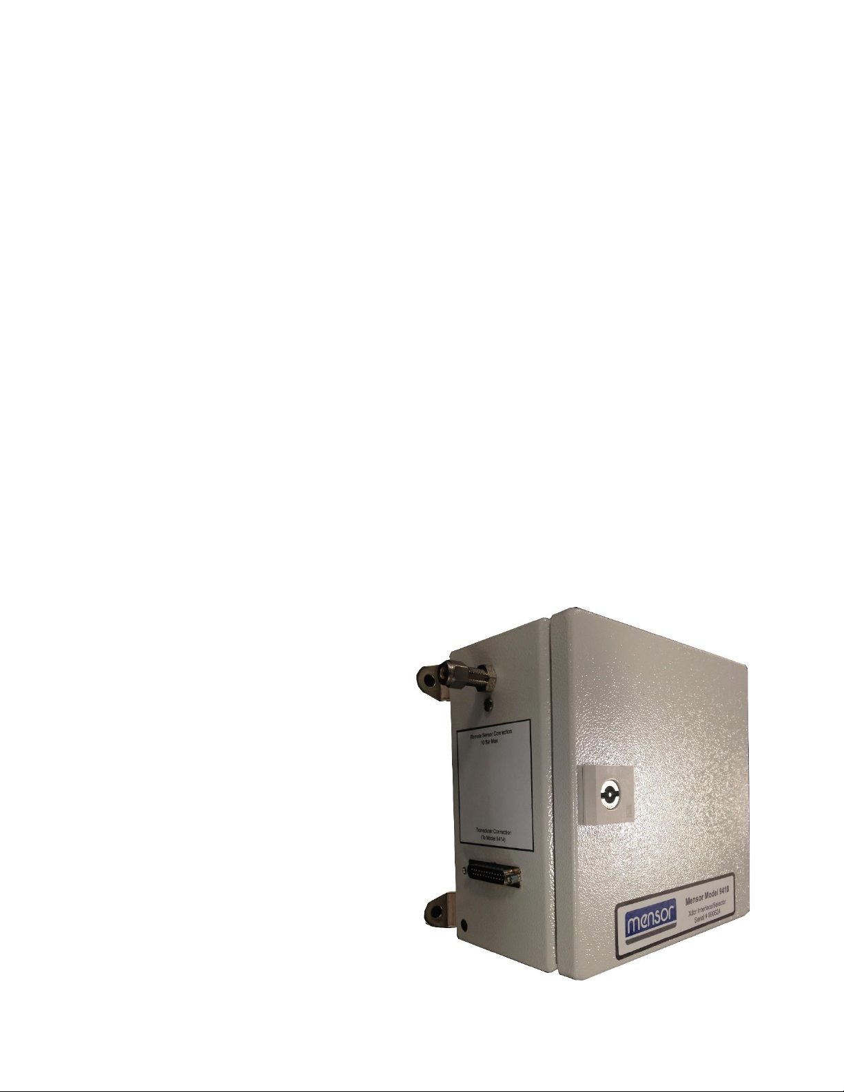
The remote transducer module
Model 9418 should be mounted
close to the devices under test to
minimize the pressure exchanges and maximize the operational speed of the
system. The 9418 is electrically connected to the Model 9415 system using the
25 pin d-sub cable provided. Pneumatic connections between the 9418 and the
device under test should be short and with minimal volume. The actual mounting
location is left to the user’s discretion.
Grounding Terminal

Mensor Model 9415 Multi-Channel Pressure Test System Manual Rev. I
14
Upgrade Section:
*This section is only applicable if a unit is being upgraded and meets the material
prerequisites.*
Prerequisites Material Assumptions:
A model 9418
A rack with a 9414 Quad, 9412, 9412, a vacuum pump, and an
emergency disconnect installed
Materials Provided:
A rack with a model 73, 9412, 9414 Dual, and a secondary 9412
Labeled Tubing
Electrical Junction box
Wires and cables
Fittings
Bracing
Setup:
Begin by removing any packing material used in
shipment and inspecting that fittings and screws are
secure and that hoses and electrical cords are not
chaffed or cut. After the unit has been confirmed to be
sound, proceed to install the Model 9414 Dual into the
top slot of the rack. There should be a total of four
screws holding the unit in.
Once the Model 9414 is secure, remove the left panel
and right panel of the rack and open the rear door if
one is installed. The removed left panel will have a
labeled I/O for different channel pressure connections.
Remove the right panel and left panel on the existing
rack and open the rear door, if one is installed. Set
aside the blank right panel for later use. The two racks
can now be bolted together using the provided
bracing. Refer to the “Brace Kit Breakdown:” &
“Bracing Installation:” sections above for greater detail.
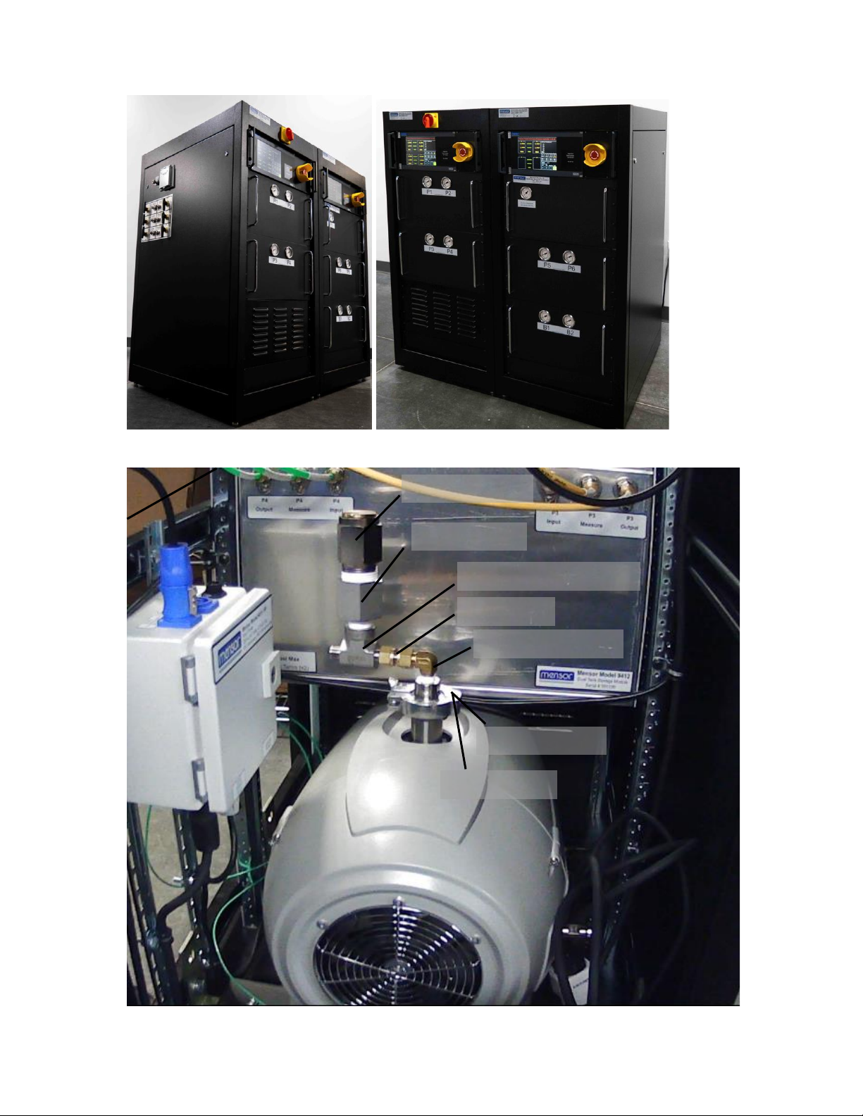
Install the panel with the various ports and legend on the left side of the newly
bolted together rack system. Install the blank panel that was set aside on the
other side. Once done it should resemble the following images.
Screw Locations
Mensor Model 9415 Multi-Channel Pressure Test System Manual Rev. I
15
Left Side: Right Side:
Vacuum Pressure Relief Valve Upgrade:
.5 PSI Relief Valve
1”x ½” Reducer
1/2” FNPT x 3/8” Tube Tee
3/8” Coupler
¼” NPT x 3/8” Elbow
1” Vacuum Flange
¼” NPT Adapter

Mensor Model 9415 Multi-Channel Pressure Test System Manual Rev. I
16
Additional fittings will need to be installed on the vacuum pump. Note that Teflon
tape should be used for all connections. Begin by installing a ¼” NPT Adapter
with a 1” Vacuum Flange on to the end of the vacuum pump. This will be followed
by a ¼” NPT x 3/8” elbow. A 3/8” coupler will need to follow the end of the elbow
which then connects to a ½” FNPT x 3/8 Tube Tee. This Tee will then connect to
a ½ ”x 1” Adapter that terminates with a .5 PSI Relief Valve. Refer to the image
above for the ideal orientation of the components.
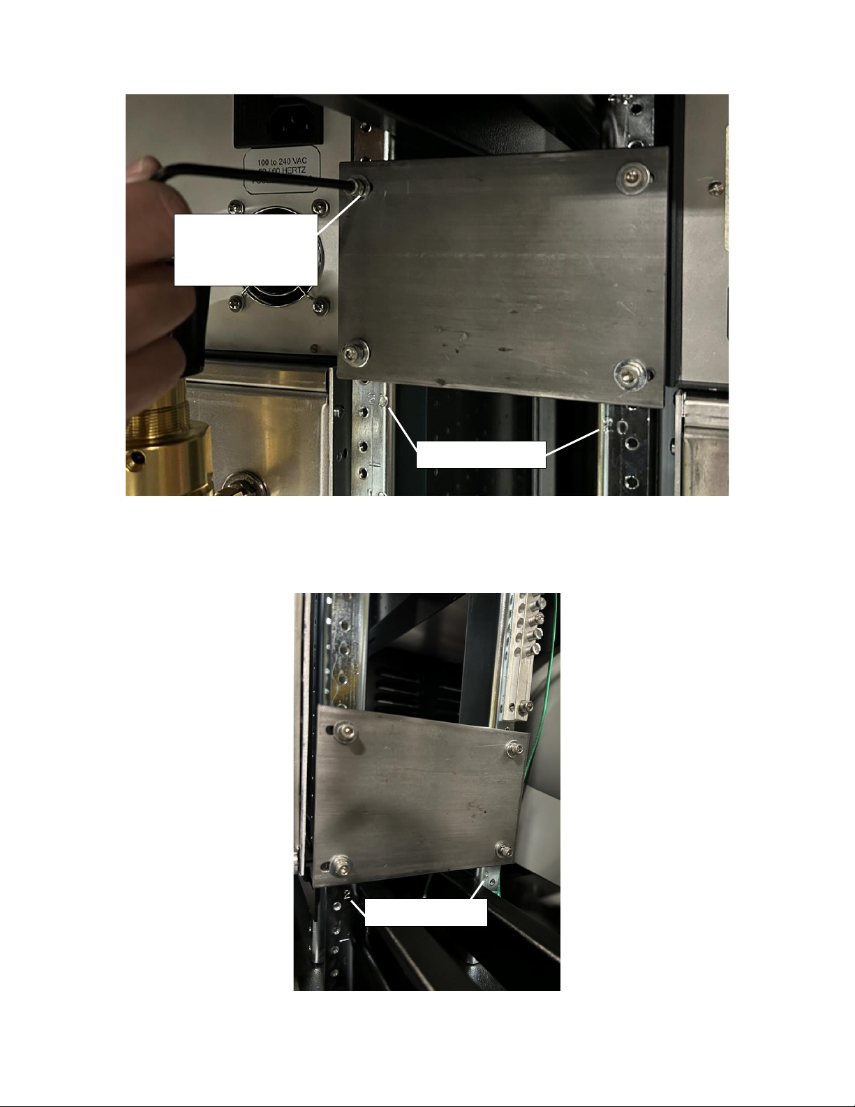
Removing The Old Power Hub:
*The machine should be powered down and unplugged.*
Before the updated electronics can be installed, the old ones must be removed.
The old power hub should be located beside the vacuum pump. Begin by
unplugging all connections. There are two main cables coming off the power hub.
Follow these cables and unplug/unscrew their terminations. More information on
removing the terminations is provided ahead. After all of the cables have been
freed, the two bolts holding the panel in place can be unscrewed. The panel with
the attached electrical junction boxes can then be removed.
Unplug Cables
Unscrew Bolts
Unplug/Unscrew Terminations
Unplug/Unscrew Terminations
Mensor Model 9415 Multi-Channel Pressure Test System Manual Rev. I
17
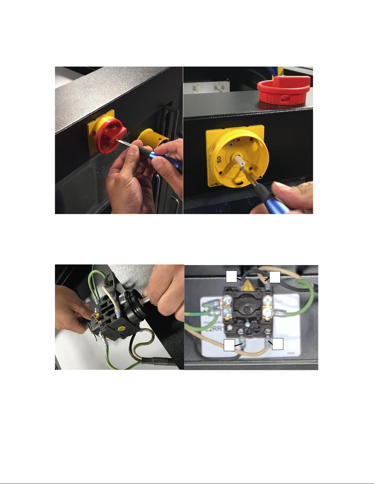
Disconnect Switch Wiring Change:
Remove the top panel of the rack with the disconnect switch. There shoud be a
total of 6 phillips screws holding the panel in place. Unscrew the red dial and
remove it from the switch. Unscrew the last two screws holding the switch’s
yellow body in place. The yellow body can be pulled off and the switch can be
pushed into the rack.
Unscrew the wires 2 and 4 from the switch. Both wires 2 and 4 can be
determined by markings on the rear of the switch. Due to the existing ground
connecting the original grouning to the mains ground, the cabe should not be
removed. Instead, the removed wires should be secured and stowed out of the
way.
Use the two-wire cable provided to connect to the 2 and 4 connections on the
switch. Ensure that the brown lead connects to 2 and the blue lead connects to 4.
1
3
4
2
Mensor Model 9415 Multi-Channel Pressure Test System Manual Rev. I
18
After the switch has been rewired, it can be reinstalled. The reinstallation process
is the inverse of the removal process. Note that the switch should be reinstalled
with the yellow triangle on top and that the wire routing of the new cables will be
shown in a later section. Ensure to reinstall and secure the top panel that was
suggested to be removed in the previous steps.
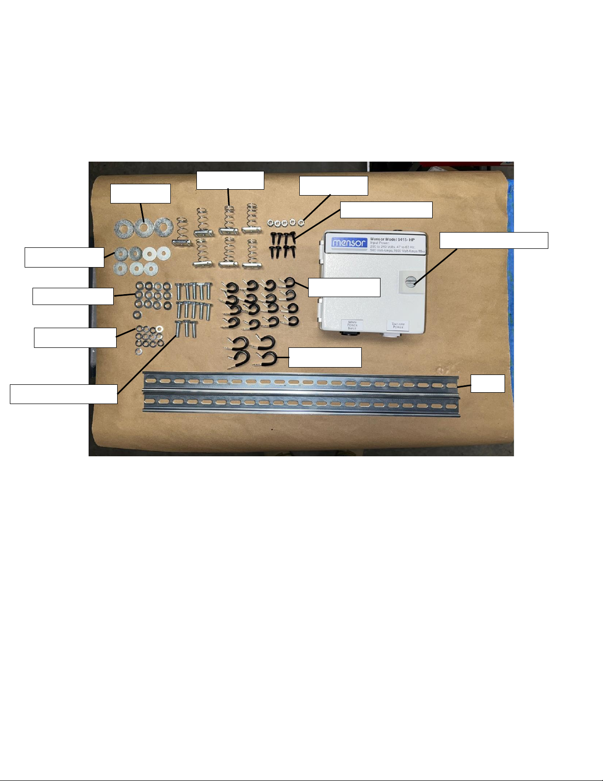
Electrical Kit Inventory:
Quantity:
½” Washer (3)
¼” x 1” Washer (7)
¼” Lock Washer (13)
¼” x 1” Hex Head Bolt (13)
¼” Rail Nut (7)
¼” Lock Nut (5)
10-32 Black Screws (8)
3/8” P-clamp (16)
5/8” P-clamp (4)
Rail (2)
Electrical Junction Box (1)
Rail
5/8”P-Clamp
½” Washer
¼” x 1” Washer
¼” Lock Washer
10-32 Black Screw
3/8”P-Clamp
¼”Lock Nut
¼” x 1” Hex Head Bolt
¼” Rail Nut
¼” Washer
Electrical Junction Box
Mensor Model 9415 Multi-Channel Pressure Test System Manual Rev. I
19
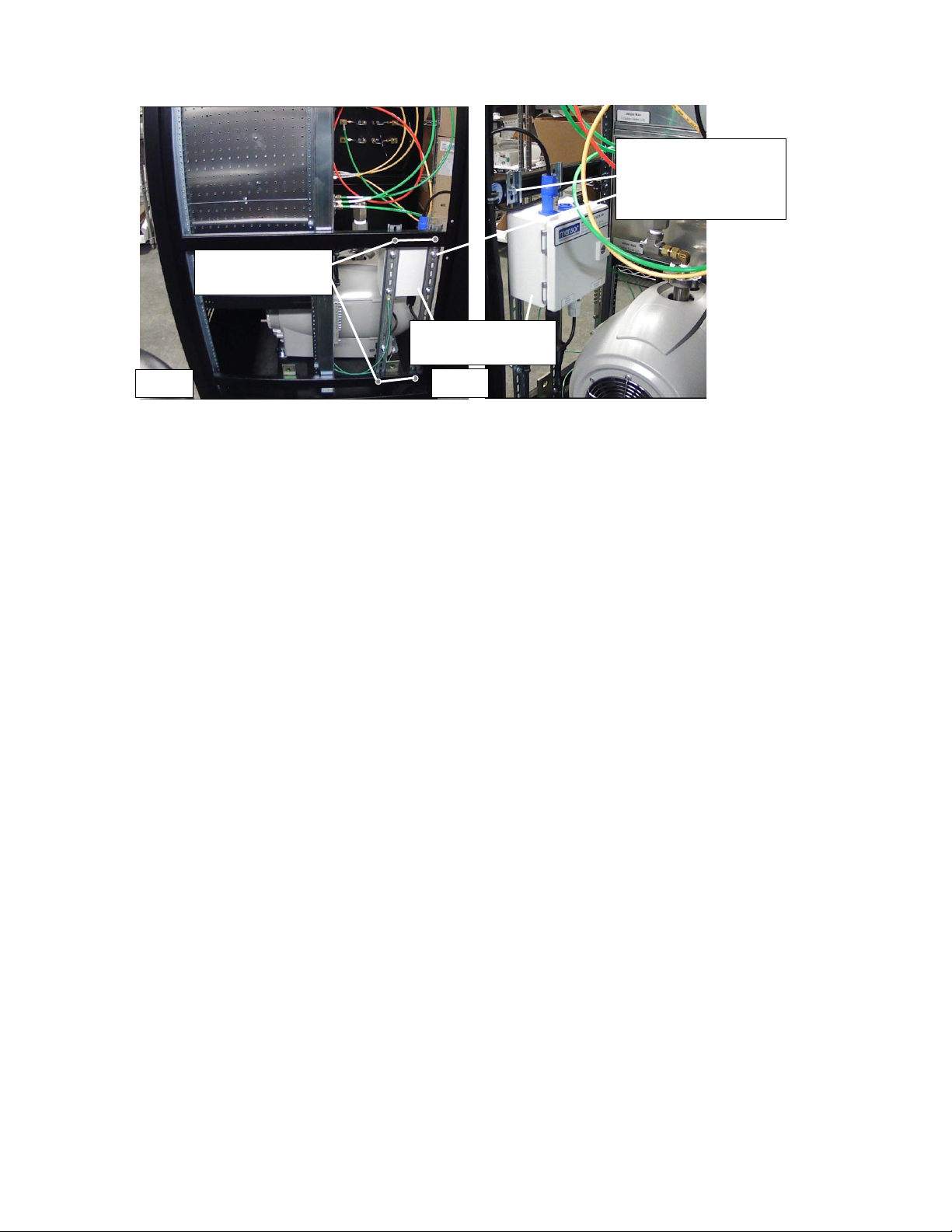
Grounding Rails Installation:
Slide 2 rail nuts into the middle and bottom rack channels as shown in the image
above. Note that this rack should be the one with the vacuum pump installed.
Use a ¼” x 1” Hex Head Bolt followed by a ¼” Lock Washer and a ¼” Washer,
then attach the Rail to each Rail Nut. The bolt should only be hand tightened to
the point that the rail is held upright, but can still slide around in the rack’s
channel. Refer to the images above as needed.
Next, attach the Electrical Junction Box to the rails. Slide the rails as needed to
get the alignment right. The Electrical Junction Box should be attached near the
top of the rails as shown in the above image. Use a ¼” x 1” Hex Head Bolt
followed by a ¼” Lock Washer and then a ¼” Washer, to bolt the Electrical
Junction Box in place in each of its four rear mounting holes. After the Electrical
Junction Box has been installed, proceed to tighten the Rail Nuts. Note that the
Electrical Junction Box should be near the rear of the rack as shown in the image
above.
Rail Nuts
Installation Points
¼” x 1” Hex Head Bolt
¼” Lock Washer
¼” Washer
Rail
Electrical Junction
Box
Front
Rear
Table of contents
Other mensor Test Equipment manuals


