manuals.online logo
Brands
  1. Home
  2. •
  3. Brands
  4. •
  5. KYORITSU
  6. •
  7. Test Equipment
  8. •
  9. KYORITSU 8128 User manual

KYORITSU 8128 User manual

INSTRUCTIONMANUAL
MODEL8128
POWERCLAMPSENSOR
Series
POWERCLAMPSENSOR
KYORITSUELECTRICALINSTRUMENTS
WORKS,LTD.
1.Safetywarnings
○Thisinstrumenthas been designed, manufactured and
tested according to IEC 61010: Safety requirements for
ElectronicMeasuringapparatus,anddelivered inthe
bestcondition after passing quality controltests.This
instructionmanual contains warnings and safety rules
whichhave to be observed by the user to ensure safe
operationof theinstrumentand tomaintainit insafe
condition.Therefore,readthroughtheseoperating
instructionsbeforeusingtheinstrument.
WARNING
●Readthroughandunderstandinstructionscontained
inthismanualbeforeusingtheinstrument.
●Keepthemanualathandto enablequickreference
whenevernecessary.
●Theinstrument istobeusedonly initsintended
applications.
Theoperating instructions described in themanual
mustbeobserved.
●Understandandfollowallthesafetyinstructions
containedinthemanual.Itisessentialthattheabove
instructionsareadheredto.Failuretofollowthe
above instructions may cause injury and or
instrumentdamage.
○The symbol indicated on the instrument, means that
theusermustrefertotherelatedpartsinthemanualfor
safeoperation of the instrument. It is essential to read
the instructions wherever the symbol appears in the
manual.
DANGER is reserved for conditions and actions
thatarelikelytocauseseriousorfatal
injury.
WARNING is reserved for conditions and actions
thatcancauseseriousorfatalInjury.
CAUTION is reserved for conditions and actions
that can cause minor injury or
instrumentdamage.
F
〜
Refertotheinstructionsinthemanual.
IndicatesaInstrumentwithdoubleorreinforced
insulation
Indicatesthatthisinstrumentcanclamponbare
conductors.
IndicatesAC
Safetysymbols
○Measurementcategories(Over-voltagecategories)
Toensuresafeoperationofmeasuringinstruments,IEC
61010establishessafetystandardsforvariouselectrical
environments,categorizedasCATⅠtoCATⅣ,and
calledmeasurementcategories.
Higher-numberedcategoriescorrespondtoelectrical
environmentswithgreatermomentaryenergy,soa
measuringinstrumentdesignedforCATⅢ environments
canenduregreatermomentaryenergythanone
designedforCATⅡ.
CAT.Ⅰ:SecondaryelectricalcircuitsconnectedtoanAC
electricaloutlet throughatransformer orsimilar
device.
CAT.Ⅱ:Primary electrical circuits of equipment
connectedtoanACelectricaloutletbyapower
cord.
CAT.Ⅲ:Primaryelectricalcircuitsoftheequipment
connecteddirectly tothe distributionpanel,and
feedersfromthedistributionpaneltooutlets.
CAT.Ⅳ:Thecircuitfrom the service drop to the service
entrance,and to the power meter andprimary
overcurrentprotectiondevice(distribution
panel).
Incoming wire
CAT.IV
Interior wiring
Transformer
CAT.I
CAT.II
CAT.III
S
ocke
t
2.Features
●ThisisaclampsensorforourPowermeter.
●Designedtointernationalsafetystandard
IEC 61010-2-032
CAT.Ⅲ 300V(PollutionDegree2)
3.Instrumentlayout
4.Dinplugpinassignment
3:GNDpin
5:Outputsignalpin
6:Sensorsignalpin
(Resistancebetween3Pin
and6Pin:91kΩ)
1,2and4:Nouse
*Above figureshows the pin assignment seeing the Clamp
sensorfrom outputconnectorpart. The figureofthe pin
assignment of connection terminal is symmetrical to above
figure.
TransformJaws
Barrier
Trigger
Cable
Outputconnector
5
3
12
4
6
DISTRIBUTOR
Kyoritsu reserves the rights to change specifications or designs
describedinthismanualwithoutnoticeandwithoutobligations.
Approx.19Ω
Model
Ratedvoltage
Outputvoltage
Measuringrange
Accuracy
(Input:sinewave)
Phase
characteristics
Temperature&humidityrange
(Guaranteedaccuracy)
Operatingtemperaturerange
Storagetemperaturerange
Maximumpermissibleinput
Output
impedance
Locationforuse
Applicable
standards
Withstand
voltage
Insulation
resistance
ConductorSize
Dimension
Cablelength
Outputterminal
Weight
Accessories
Accessories
23±5℃,relativehumidity:85%orless(nocondensation)
0〜50℃,relativehumidity:85%orless(nocondensation)
-20〜60℃,relativehumidity:85%orless(nocondensation)
IEC61010-1,IEC61010-2-032
MeasurementCAT.III(300Vrms)
Pollutiondegree2
IEC61326
AC3540Vrms(50/60Hz)for5sec.
betweenJawandenclosure
betweenenclosureandoutputterminal
betweenJawandoutputterminal
50MΩ orgreaterat1000V
betweenJawandenclosure
betweenenclosureandoutputterminal
betweenJawandoutputterminal
5.Specifications
Approx.3m
MINIDIN6PIN
8128
AC5A
10mV/A(AC50mV/AC5A)
(AC500mV/AC50A)
AC0〜50Arms(70.7Apeak)
±0.5%rdg±0.1mV
(50/60Hz)
±1.0%rdg±0.2mV
(40〜1kHz)
±2degwithin(at0.5〜50A/45〜65Hz)
AC50Armscontinuous(50/60Hz)
Altitudeupto2000m,Indoors
Approx.24mmindiameter(max.)
100x60x26mm
Approx.160g
Cablemarker
Instructionmanual
MODEL7146(BananaF4adjusterplug)
MODEL7185(Extensioncable)
Conductor
Load
Currentdirection
arrow
Power
source
6-1Measurementprocedures
(1)Connectthe Output connector to theInput terminal of
themeasuringinstrument.
(2)Pressthe Triggertoopenthe transformer jawsand
clampontooneconductor.Inthiscase,themeasured
conductorshallbeatthecenterofthejaws.
Whenconnecting a sensorwitha Power meter(our
Powermeter,MODEL6300,etc.)matchthearrowmark
(Powersourcetoload),whichisindicatedonthe
transformerjaws, with the current flowing direction in
0ordertosynchronizethephasesofmeasuredcurrent
andoutputvoltage.
(3)Ensurethatthetipsoftransformerjawsarefirmly
closed.
5/10/20/50A50AMODEL8128
6-2SettingforMODEL6300Powermeter
Referto the tablebelowwhenusing these clampsensors
with MODEL6300, It shows the settings for clamp sensor
andavailablecurrentrangesonMODEL6300.
Forfurtherdetailsonthesettings,seetheinstruction
manualforMODEL6300.
MODEL
SettingforMODEL6300
Typeof
Clampsensor Currentrange
www. .com information@itm.com1.800.561.8187
INSTRUCTIONMANUAL
MODEL8128
POWERCLAMPSENSOR
Series
POWERCLAMPSENSOR
KYORITSUELECTRICALINSTRUMENTS
WORKS,LTD.
DANGER
●Never make measurement on a circuit in which the
electricalpotentialexceedsAC300V.
●Donotmakemeasurementwhenthunderrumbling.If
theinstrumentisinuse,stopthemeasurement
immediatelyandremovetheinstrumentfromthe
measuredobject.
●Donotattempttomakemeasurementinthe
presenceofflammablegasses.Otherwise,theuseof
theinstrument may causesparking, which canlead
toanexplosion.
●Thetransformer jaws aremadeofmetaland their
tipsarenotcompletelyinsulated.Beespecially
carefulaboutthepossibleshortingwherethe
measuredobjecthasexposedmetalparts.
●Neverattempttousetheinstrumentifit'ssurfaceor
yourhandarewet.
●Donotexceedthemaximumallowableinputofany
measuringrange.
WARNING
●Neverattempttomakeanymeasurement,ifany
abnormalconditionsarenoted,suchasbrokencase,
andexposedmetalparts.
●Do not install substitute parts or make any
modificationtotheinstrument.Returntheinstrument
tothedistributorfromwhoyoupurchasedthis
instrumentforrepairorre-calibrationincaseof
suspectedfaultyoperation.
●Alwayskeepyourfingersandhandsbehindthe
barrierontheinstrumenttoavoidthepossibleshock
hazard.
CAUTION
●Donotsteponorpinchthecordtopreventthejacket
ofcablefrombeingdamaged.
●Theoutputconnectorshallberemovedorconnected
withoutclampingaconductor.Otherwise,itmay
causeafailure.
●Donotexposetheinstrumenttodirectsunlight,high
temperatures,humidityordew.
●Nevergiveshocks,suchasvibrationordrop,which
maydamagetheinstrument.
●Useadampclothanddetergentforcleaning the
instrument.Donotuseabrasivesorsolvents.
5
3
12
4
6
92-1800B5-12
DISTRIBUTOR
Kyoritsu reserves the rights to change specifications or designs
describedinthismanualwithoutnoticeandwithoutobligations.
5.Specifications
6.Operatinginstructions
DANGER
●Nevermakemeasurementonacircuitinwhichthe
electricalpotentialexceedsAC300Vin ordertoavoid
possibleshockhazard.
●Thetransformerjawsaremadeofmetalandtheirtips
arenotcompletelyinsulated.Beespeciallycareful
aboutthepossibleshortingwherethemeasuredobject
hasexposedmetalparts.
CAUTION
●Takesufficientcaretoavoidshock,vibrationor
excessiveforcewhenhandlingtheinstrument.
Otherwise, precisely adjusted transformer jaws will
bedamaged.
●Whentransformerjaws do not fullyclose,never try to
closethembyforce,butmakethemfreetomoveand
tryagain.Ifaforeignsubstanceisstuckinthejaw
tips,removeit.
●Whenmakingcurrentmeasurements,keepthe
transformerjawsfullyclosed.
Otherwise,accuratemeasurements cannot be taken.
Maximumconductorsizeis24mmindiameter.
●Holdtheinsertingpart(exceptforthecable)and
disconnecttheOutput connector from themeasuring
instrumentsoasnottocauseabreakinthecable.
MODEL
SettingforMODEL6300
Typeof
Clampsensor Currentrange
www. .com information@itm.com1.800.561.8187
INSTRUCTIONMANUAL
MODEL8128
POWERCLAMPSENSOR
Series
POWERCLAMPSENSOR
KYORITSUELECTRICALINSTRUMENTS
WORKS,LTD.
1.Safetywarnings
○Thisinstrumenthas been designed, manufactured and
tested according to IEC 61010: Safety requirements for
ElectronicMeasuring apparatus,anddelivered inthe
bestcondition after passing quality controltests.This
instructionmanual contains warnings and safety rules
whichhave to be observed by the user to ensure safe
operationof theinstrumentand tomaintainit insafe
condition.Therefore,readthroughtheseoperating
instructionsbeforeusingtheinstrument.
WARNING
●Readthroughandunderstandinstructionscontained
inthismanualbeforeusingtheinstrument.
●Keepthemanualathandto enablequickreference
whenevernecessary.
●Theinstrument istobeusedonly initsintended
applications.
Theoperating instructions described in themanual
mustbeobserved.
●Understandandfollowallthesafetyinstructions
containedinthemanual.Itisessentialthattheabove
instructionsareadheredto.Failuretofollowthe
above instructions may cause injury and or
instrumentdamage.
○The symbol indicated on the instrument, means that
theusermustrefertotherelatedpartsinthemanualfor
safeoperation of the instrument. It is essential to read
the instructions wherever the symbol appears in the
manual.
DANGER is reserved for conditions and actions
thatarelikelytocauseseriousorfatal
injury.
WARNING is reserved for conditions and actions
thatcancauseseriousorfatalInjury.
CAUTION is reserved for conditions and actions
that can cause minor injury or
instrumentdamage.
F
〜
Refertotheinstructionsinthemanual.
IndicatesaInstrumentwithdoubleorreinforced
insulation
Indicatesthatthisinstrumentcanclamponbare
conductors.
IndicatesAC
Safetysymbols
○Measurementcategories(Over-voltagecategories)
Toensuresafeoperationofmeasuringinstruments,IEC
61010establishessafetystandardsforvariouselectrical
environments,categorizedasCATⅠtoCATⅣ,and
calledmeasurementcategories.
Higher-numberedcategoriescorrespond toelectrical
environmentswithgreatermomentaryenergy,soa
measuringinstrumentdesignedforCATⅢ environments
canenduregreatermomentaryenergythanone
designedforCATⅡ.
CAT.Ⅰ:SecondaryelectricalcircuitsconnectedtoanAC
electricaloutletthroughatransformerorsimilar
device.
CAT.Ⅱ:Primary electrical circuits of equipment
connectedtoanACelectricaloutletbyapower
cord.
CAT.Ⅲ:Primaryelectricalcircuitsoftheequipment
connecteddirectlytothedistributionpanel,and
feedersfromthedistributionpaneltooutlets.
CAT.Ⅳ:Thecircuit from the service drop tothe service
entrance,and to the power meter and primary
overcurrentprotectiondevice(distribution
panel).
Incoming wire
CAT.IV
Interior wiring
Transformer
CAT.I
CAT.II
CAT.III
S
ocke
t
2.Features
●ThisisaclampsensorforourPowermeter.
●Designedtointernationalsafetystandard
IEC 61010-2-032
CAT.Ⅲ 300V(PollutionDegree2)
3.Instrumentlayout
4.Dinplugpinassignment
3:GNDpin
5:Outputsignalpin
6:Sensorsignalpin
(Resistancebetween3Pin
and6Pin:91kΩ)
1,2and4:Nouse
*Above figureshows the pinassignment seeing the Clamp
sensorfromoutputconnectorpart.Thefigure of the pin
assignment of connection terminal is symmetrical to above
figure.
TransformJaws
Barrier
Trigger
Cable
Outputconnector
5
3
12
4
6
92-1800B5-12
DISTRIBUTOR
Kyoritsu reserves the rights to change specifications or designs
describedinthismanualwithoutnoticeandwithoutobligations.
Approx.19Ω
Model
Ratedvoltage
Outputvoltage
Measuringrange
Accuracy
(Input:sinewave)
Phase
characteristics
Temperature&humidityrange
(Guaranteedaccuracy)
Operatingtemperaturerange
Storagetemperaturerange
Maximumpermissibleinput
Output
impedance
Locationforuse
Applicable
standards
Withstand
voltage
Insulation
resistance
ConductorSize
Dimension
Cablelength
Outputterminal
Weight
Accessories
Accessories
23±5℃,relativehumidity:85%orless(nocondensation)
0〜50℃,relativehumidity:85%orless(nocondensation)
-20〜60℃,relativehumidity:85%orless(nocondensation)
IEC61010-1,IEC61010-2-032
MeasurementCAT.III(300Vrms)
Pollutiondegree2
IEC61326
AC3540Vrms(50/60Hz)for5sec.
betweenJawandenclosure
betweenenclosureandoutputterminal
betweenJawandoutputterminal
50MΩ orgreaterat1000V
betweenJawandenclosure
betweenenclosureandoutputterminal
betweenJawandoutputterminal
5.Specifications
Approx.3m
MINIDIN6PIN
8128
AC5A
10mV/A(AC50mV/AC5A)
(AC500mV/AC50A)
AC0〜50Arms(70.7Apeak)
±0.5%rdg±0.1mV
(50/60Hz)
±1.0%rdg±0.2mV
(40〜1kHz)
±2degwithin(at0.5〜50A/45〜65Hz)
AC50Armscontinuous(50/60Hz)
Altitudeupto2000m,Indoors
Approx.24mmindiameter(max.)
100x60x26mm
Approx.160g
Cablemarker
Instructionmanual
MODEL7146(BananaF4adjusterplug)
MODEL7185(Extensioncable)
Conductor
Load
Currentdirection
arrow
Power
source
6-1Measurementprocedures
(1)Connectthe Output connector to the Inputterminal of
themeasuringinstrument.
(2)PresstheTriggertoopenthe transformer jawsand
clampontooneconductor.Inthiscase,themeasured
conductorshallbeatthecenterofthejaws.
Whenconnectingasensorwith a Powermeter(our
Powermeter,MODEL6300,etc.)matchthearrowmark
(Powersourcetoload),whichisindicatedonthe
transformerjaws, with the current flowingdirection in
0ordertosynchronizethephasesofmeasuredcurrent
andoutputvoltage.
(3)Ensurethatthetipsoftransformerjawsarefirmly
closed.
5/10/20/50A50AMODEL8128
6-2SettingforMODEL6300Powermeter
Refertothetable below whenusingtheseclamp sensors
with MODEL6300, It shows the settings for clamp sensor
andavailablecurrentrangesonMODEL6300.
Forfurtherdetailsonthesettings,seetheinstruction
manualforMODEL6300.
MODEL
SettingforMODEL6300
Typeof
Clampsensor Currentrange
www. .com information@itm.com1.800.561.8187
This manual suits for next models

1

Other KYORITSU Test Equipment manuals

KYORITSU KEW 8146 User manual

KYORITSU

KYORITSU KEW 8146 User manual

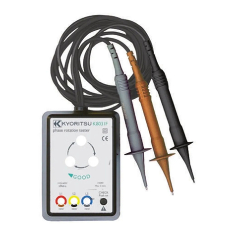
KYORITSU K8031F User manual

KYORITSU

KYORITSU K8031F User manual

KYORITSU KEW 4105A User manual

KYORITSU

KYORITSU KEW 4105A User manual

KYORITSU KEW SNAP 2434 User manual

KYORITSU

KYORITSU KEW SNAP 2434 User manual

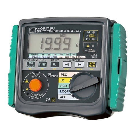
KYORITSU 6050 User manual

KYORITSU

KYORITSU 6050 User manual

KYORITSU KEW3125A User manual

KYORITSU

KYORITSU KEW3125A User manual

KYORITSU PACKTEST Glucose User manual

KYORITSU

KYORITSU PACKTEST Glucose User manual

KYORITSU 4118A User manual

KYORITSU

KYORITSU 4118A User manual

KYORITSU kew 4300 User manual

KYORITSU

KYORITSU kew 4300 User manual

KYORITSU 6010A User manual

KYORITSU

KYORITSU 6010A User manual

KYORITSU 3132A User manual

KYORITSU

KYORITSU 3132A User manual

KYORITSU KEW 3022 User manual

KYORITSU

KYORITSU KEW 3022 User manual

KYORITSU 6011A User manual

KYORITSU

KYORITSU 6011A User manual

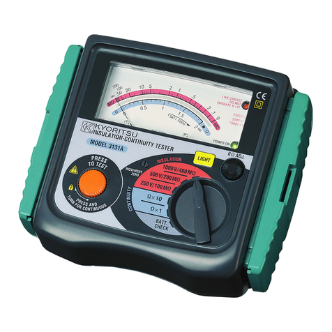
KYORITSU 3131A User manual

KYORITSU

KYORITSU 3131A User manual

KYORITSU KEW FORK User manual

KYORITSU

KYORITSU KEW FORK User manual

KYORITSU KEW8031F User manual

KYORITSU

KYORITSU KEW8031F User manual

KYORITSU KEW4105DL User manual

KYORITSU

KYORITSU KEW4105DL User manual

KYORITSU KEW6201A User manual

KYORITSU

KYORITSU KEW6201A User manual

KYORITSU 4116A Guide

KYORITSU

KYORITSU 4116A Guide

KYORITSU KEW 6010B User manual

KYORITSU

KYORITSU KEW 6010B User manual

KYORITSU KEW3431 User manual

KYORITSU

KYORITSU KEW3431 User manual

KYORITSU 8031 User manual

KYORITSU

KYORITSU 8031 User manual

KYORITSU 3021A User manual

KYORITSU

KYORITSU 3021A User manual

KYORITSU KEW 6016 User manual

KYORITSU

KYORITSU KEW 6016 User manual

Popular Test Equipment manuals by other brands

PCB Piezotronics 8159-0112A Installation and operating manual

PCB Piezotronics

PCB Piezotronics 8159-0112A Installation and operating manual

Nidec DT-3015P instruction manual

Nidec

Nidec DT-3015P instruction manual

Horotec FLASHTEST manual

Horotec

Horotec FLASHTEST manual

Amprobe AMB-110 user manual

Amprobe

Amprobe AMB-110 user manual

AEMC instruments 8510 user manual

AEMC instruments

AEMC instruments 8510 user manual

Sonotec Airborne Sound Sensor BS10 User documentation

Sonotec

Sonotec Airborne Sound Sensor BS10 User documentation

Furukawa OFS P10188-10 manual

Furukawa

Furukawa OFS P10188-10 manual

Capstan Turf Sprayer Edition SharpShooter With Rate... Operator and  maintenance manual

Capstan

Capstan Turf Sprayer Edition SharpShooter With Rate... Operator and maintenance manual

LumaSense technologies IRC Series manual

LumaSense technologies

LumaSense technologies IRC Series manual

Tektronix 2440 user manual

Tektronix

Tektronix 2440 user manual

SCS 770065 user guide

SCS

SCS 770065 user guide

YOKOGAWA DL7440 user manual

YOKOGAWA

YOKOGAWA DL7440 user manual

Valex S800146 operating instructions

Valex

Valex S800146 operating instructions

IDEAL INDUSTRIES 61-796 Technical manual

IDEAL INDUSTRIES

IDEAL INDUSTRIES 61-796 Technical manual

mensor PCS 400 Operation manual

mensor

mensor PCS 400 Operation manual

Sera Aqua-Test Series INFORMATION FOR USE

Sera

Sera Aqua-Test Series INFORMATION FOR USE

Teledyne FST-040 manual

Teledyne

Teledyne FST-040 manual

CBE PT652 user manual

CBE

CBE PT652 user manual

manuals.online logo
manuals.online logoBrands
  • About & Mission
  • Contact us
  • Privacy Policy
  • Terms and Conditions

Copyright 2025 Manuals.Online. All Rights Reserved.