Merax MS186767BAA User manual

BICYCLE
ASSEMBLY
INSTRUCTIONS
MERAX.COM
Universal version manual: Pictures and accessories in the manual may be somewhat
different from the actual unit you purchase.
TEL: 626-912-8886 Ext. 100
Bike Helpcenter : www.merax.com/helpcenter.html

SERIALNUMBER:
|PLEASE RECORD YOUR SERIAL NUMBER HERE
INVOICENUMBER:
|PLEASE RECORD YOUR INVOICE NUMBER HERE
Your Serial number is located beneath your bottom bracket where the pedals attach.
Authorities will require your serial number to identify your bicycle should it be lost or stolen.
BICYCLEOVERVIEW INTRODUCTION
CONGRATULATIONS ON PURCHASING YOUR BRAND NEW Merax BICYCLE!
Your bicycle comes to you requiring some assembly. This guide has been written to help you through the
steps necessary to complete the assembly of your bike.
THESE INSTRUCTIONS WILL GUIDE YOU THROUGH:
Inspectingthebike
Installingthehandlebars
Installingyourpedals
Battery Protection
Attachingthereflectors
Unpackingthebike
Installingthefrontwheel
Installingthesaddleandseatpost
Bike riding operation
Inflatingthetyres
INTHEINTERESTOFSAFETYITISRECOMMENDED
THATYOUHAVETHISBICYCLEASSEMBLEDBYA
SKILLEDBICYCLEMECHANIC.
These instructions are to be used as a guide only;
the images used throughout are for demonstration purposes only and may not be images of your specific bike.
1
VERYIMPORTANT
2
BEFOREYOUSTART
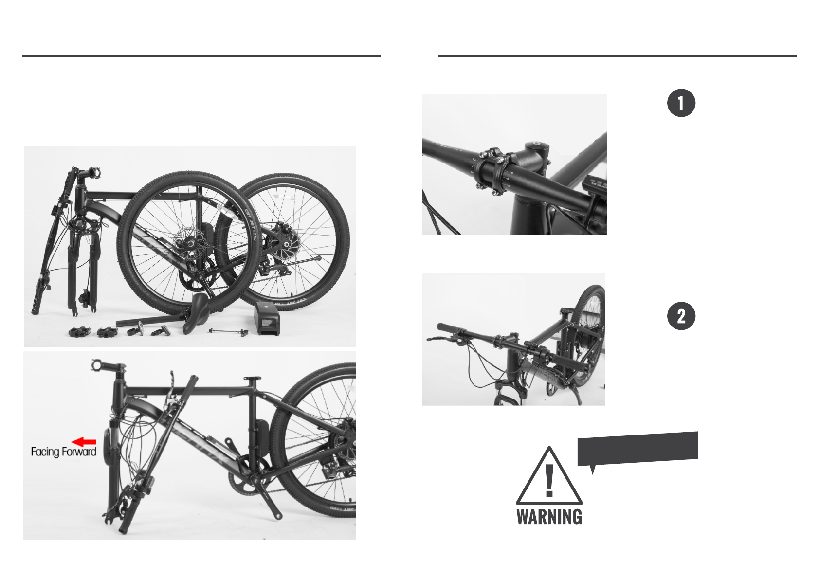
UNPACKING THE BIKE
Make sure the fork is in the correct position before mounting the handlebar and
wheel (fork arch should be facing forward ):
3
INSTALLINGTHEHANDLEBARS
Remove the 4 screws on the stem, take off the
stem plate, mount the handlebar to the stem
(make sure all the cables are put properlly),
hand tighten the bolts to secure the faceplate,
STEP
STEP
Center the bar, use the white mark as a guide.
Ensure there is an equal amount of mark on
both sides of the stem, Once centered, use
your Allen wrench to slightly tighten the
faceplate down.
THE FORK MUST BE PUT IN CORRECT POSITION
The fork arch should be facing forward before
assemble the handlebar.
EV RYIMPORTANT

45
INSTALLINGTHEFRONTWHEEL
|NUTTED FRONT WHEELS
Remove the fork protection screw (Protection purpose only, no longer needed)
Lock the quick release lever
INSTALLINGYOURPEDALS
|ALL BIKE MODELS
WARNING: INCORRECTATTACHMENTOFTHEPEDAL
into the crank arm can strip the thread from the pedal spindle,
or threads in the crank arm, and cause irreparable damage.
Incorrect assembly is not covered under warranty.
Identify Left vs Right pedal. There is an “L” or “R”stamped into the metal part of the pedal near
the threaded part or on the spindle of the pedals . NOTE: they are not the same!
If you were to sit on the bike and hold the handlebars, your “left” foot is on the same side as the “left” pedal.
STEP
EV RYIMPORTANT
IMPORTANTNOTE
Attach the front wheel to the fork and insert the quick release lever through the wheel axle.

7
INSTALLINGYOURPEDALS
Install the left hand pedal first. You will have
to screw it in COUNTER-CLOCKWISE because
the threading is the reverse of a normal
screw.
DO NOT USE A SPANNER until you are ready
to tighten it for the final few turns. Tighten it
until you can’t anymore.
STEP STEP
If the pedals are not fully tightened, they may get loose and damage the threads, it is NOT
covered by your warranty.
Tighten the pedals until you can't anymore. If
you feel you do not have enough hand strength
you can slide a pipe over the wrench to extend
the lever and get more force
INSTALLINGYOURPEDALS
Install the right hand pedal . You will have to
screw it in CLOCKWISE like a normal screw.
DO NOT USE A SPANNER until you are ready
to tighten it for the final few turns. Tighten it
until you can’t anymore.
Tighten the pedals until you can't anymore. If
you feel you do not have enough hand strength
you can slide a pipe over the wrench to extend
the lever and get more force
If the pedals are not fully tightened, they may get loose and damage the threads, it is NOT
covered by your warranty.
6

9
INSTALLINGTHE SEATPOST
| ATTACHING THE SEATPOST
Depending on your bicycle’s design, this process may differ.
Insert the seat post into the frame. There is a
minimum insertion marked on the seat post.
This must be situated below the seat post
clamp when riding to avoid accidents and
damage.
STEP
STEP
Make sure the MINIMUM INSERTION LINE on the post is
below the top of the seat tube, so that it is not visible.
Failure to do so will damage the seat tube and void the
warranty.
VERYIMPORTANT
Rotate the seat post lever clockwise and lock
it tightly as shown
INSTALLINGTHE BATTERY
The charging plug is on the battery body, plug the
charger into the battery body. you will see the red
light go ON.
STEP
STEP
When the indicator is red,it is charging normally
When the indicator is green,the battery is charged
fully.
8
Install Headlight
Fix the front head light onto front carrier and
tighten the screw
STEP
11
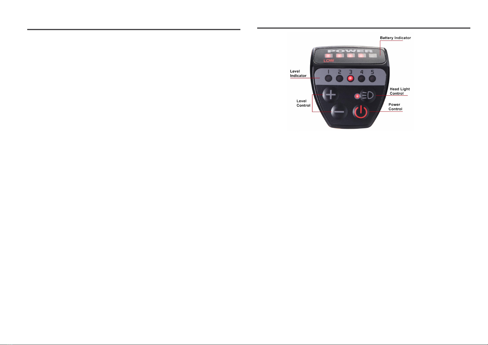
BIKE RIDDING OPERATION
1. Power Button
Press power button to switch ON/OFF the Pedal Assisstance Mode.
2. Increase/Decrease Speed
Press + or – to increase/decrease the speed of pedal assistance desired between 1 to 5.
Always start off slowly and gradually speed up. Make sure your speed is appropriate to the road
condition.
3. Headlight Control
Press the headlight button to switch ON/OFF of the headlight.
You will see the light turn RED when the headlight is switched on.
4. Battery Indicator
The battery indicator informs how much power is left in the battery.
The battery is fully charged when all 5 bars are lit up, and the bike needs charging when only Low bar is
lit up.
5.Level Indicator
Display current speed level
BATTERY PROTECTION
For maximizing the life of your battery and protection,please read the following instructions in
this guide.
▲ Charging the battery 100% fully at first time for the new e bike before ridding.
▲ Even with proper care, rechargeable batteries do not last forever. Every time the battery is
discharged and subsequently recharged. Its relative capacity decreases by a small percentage.
You can
▲Li-LON recommended charging time:4-6 hours
▲For a complete,100% charging, leave the battery on the charger for one full hour after the
charger indicator light turns green.
▲Never charge batteries for longer than 24 hours.
▲Li-ion batteries do not have a "memory." Partial discharge/charge cycles will not harm the
batteries capacity or performance.
▲The rated output capacity of a battery is measured at 77”F(25”C). Any variation in this
temperature will alter the performance of the battery, and shorten its expected life. High
temperatures especially reduce overall battery life &running time.
▲Always be sure to turn the bike power switch to “OFF” after each use. If you leave the power
switch on the “ON” position, or your product has not been charged for a long period of time, the
battery may reach a stage at which they will no longer hold a charge.
10
Battery Charging
Plug the charger into the battery body, you will see the red light go ON.
When the indicator is red, it is charging normally. When the indicator is green, the battery is charged
fully.

13
BIKE RIDDING OPERATION
There are two modes,You can choose one of them when riding.
1. PAS mode
Press the Power Button and you will automatically enter PAS Mode, you
can change your speed from 1 - 5 by pressing "+" and "-". In this mode, the
motor only provides power when you are pedaling.
2.Throttle mode
When pressing the thumb throttle , you will enter throttle mode, the motor
provides power and propels you and the bike forward.
ATTACHING THE REFLECTORS
1. Front reflector
2.Rear reflector
Install front and rear reflectors as shown below:
12
Front reflector goes on the handlebar
Rear reflector goes on the stem below the seat. Don’t place the rear reflector too high,
or its reflection might be blocked by the seat or the bottom of your shirt.

14 15
TUNINGTHEGEARS-REARDÉRAILLEUR
|ADJUST THE CABLE
Front Derailleurs Adjust:
http://youtu.be/tfBiXgf8JxI
EV RYIMPORTANT
Make sure the chain is on the smallest rear sprocket
and that the gear shifter is in the highest position
(highest gear).
STEP
STEP
Loosen the clamp on the under section of the
dérailleur where the cable is gripped.
Pull any cable slack through the clamp and
re-tighten.
2
TUNINGTHEGEARS-REARDÉRAILLEUR
|LIMIT SCREWS
|ADJUST UPPER LIMIT
To limit the movement of the rear dérailleur so that
it doesn’t shift into the chain stay, you’ll need to use
the UPPERLIMITSCREW(H) located on the back
of the dérailleur body.
Turning this screw clockwise moves the top jockey
wheel to the left, and turning it anti-clockwise
moves it to the right.
Shift the rear dérailleur into the smallest sprocket
and adjust it until the centre line of the top jockey
wheel is in-line with the smallest sprocket.
|ADJUST LOWER LIMIT
The low adjustment will stop the chain from over-
shifting beyond the largest sprocket and causing the
chain to jump into the spokes of the rear wheel.
Turning theLOWERLIMITSCREW(L) clockwise
will move the top jockey wheel to the right and anti-
clockwise will move it to the left.
Shift the rear dérailleur into the largest sprocket
and adjust the screw until the centre line of the
top jockey wheel is directly in-line with the largest
sprocket.
UPPERLIMITSCREW(H)
LOWERLIMITSCREW(L)
STEP STEP
Rear Derailleurs Adjust:
http://youtu.be/wQncKmddahk

16 17
TUNINGTHEGEARS-REARDÉRAILLEUR
|BARREL ADJUSTER
| To adjust the dérailleur cable tension, shift the
chain onto the smallest sprocket and try to shift
on to the second sprocket by changing the gear on
the handlebar.
| If it doesn’t quite make it, rotate the barrel
adjuster on the dérailleur ANTI-CLOCKWISETO
INCREASETHECABLETENSION.
| If it over-shifts and tries to get onto the third
sprocket, turn the adjuster CLOCKWISETO
DECREASETHECABLETENSION.
| When it works between one and two, check the
shifting across the rest of the gears and tweak the
barrel adjuster if necessary.
| NEWCABLESCANSTRETCHANDLOSE
TENSIONAFTERITSFIRSTPERIODOFUSE.
You’ll notice that the gears move slightly out of
adjustment and will begin to hesitate or over-shift.
| TOFIXTHIS; you will need to remove the slack
from the cable using the barrel adjustment.
| If there is lots of slack in the cable and cannot be
taken up using the barrel adjuster, you will need to
pull the excess cable through the clamp, like in the
first step.
TUNINGTHEGEARS-FRONTDÉRAILLEUR
|ADJUST THE CABLE
WARNING: YOURGEARSARENOTTUNED.Tuning the
gears correctly is very important. Failure to do so will void your
warranty and may cause injury while riding! If your bicycle has
gears and you are unsure how to tune and adjust them, you must
seek an experienced bicycle mechanic
EV RYIMPORTANT
Make sure the chain is on the smallest chain ring,
and that the gear shifter is in its lowest position
(lowest gear).
STEP
STEP
Loosen the clamp where the cable is gripped to
the dérailleur.
Pull through any cable slack and tighten.

18 19
TUNINGTHEGEARS-FRONTDÉRAILLEUR
|LIMIT SCREWS
Limit screws stop the inward and outward travel of the front dérailleur. Limit screws are marked “L” & “H”.
The L-screw will stop the motion of the dérailleur toward the smallest sprocket. The H-screw will stop the
motion of the dérailleur toward the largest chain ring.
|ADJUST UPPER LIMIT
Shift the dérailleurs to the largest chain ring on
the rear gears, and the smallest sprocket on the
front gears.
Turn the low gear limit on the top of the dérailleur
with the Phillips head screwdriver to adjust the
dérailleur so that it prevents the chain from coming
off the smallest sprocket. You are looking for a very
small gap.
|ADJUST LOWER LIMIT
Shift the dérailleurs to the smallest rear sprocket
and the largest front chain ring.
Turn the high gear limit on the top of the dérailleur
to adjust the dérailleur cage so that it just clears the
chain on the largest sprocket.
UPPERLIMITSCREW(H)
LOWERLIMITSCREW(L)
STEP STEP
INFLATINGTHETYRES
|SCHRADER VALVE (SV)
(Sometimes referred to as an American Valve [AV])
A Schrader valve is commonly found on mountain bikes and hybrids. It is also used on cars.
The valve stem is surrounded by a threaded valve cylinder; to press down on the stem, you need to use a tool
like a pen cap or your thumbnail.
Schrader valves are typically wider in diameter and shorter than Presta.
|VALVE TYPE
To open a Schrader valve, simply unscrew the cap at
the top.
Place the pump on the valve, pump to the required
pressure and remove the pump.
|PRESSURE
The required pressure is printed on the side wall of
the bicycles tyres
MIN.50/MAX.85PSI (Pressure per Square Inch) – This means that the pressure required in your tyre
is no less than 50 PSI and no more than 85 PSI. To accurately see this pressure, you will require a pump
with a pressure gauge.
Table of contents


