Contents
i
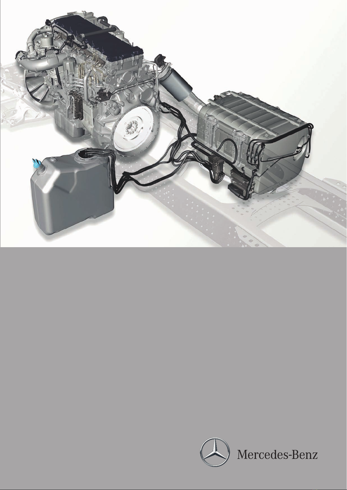
Introduction of engine OM 471 and exhaust aftertreatment >09/2011 >
7
Component description for coolant pump B640, Y631
iOnly in vehicles with code (M7T)
Coolant pump, controlled.
No component description was created for
vehicles with a rigid coolant pump.
Page 160
Residual heat pump, component description M20
iOnly in vehicles with code (D6I)
Residual heat utilization.
Page 162
Tachograph (TCO) component description P1
Page 163
Electronic ignition lock (EIS), component
description
S1
Page 164
EMERGENCY OFF switch, component
description
S30
iOnly in vehicles with one of the
following codes:
•
Code (E5T) ADR model class EX/II,
including AT
•
Code (E5U) ADR model class EX/III,
including EX/II and AT
•
Code (E5V) ADR model class FL,
including EX/II, EX/III and AT
•
Code (E5X) ADR model class AT
•
Code (E5Z) Accessories, ADR
•
Code (E9D) Preinstallation, for bipolar
battery disconnect switch
•
Code (E9E) ADR preinstallation, without
chassis shielding
Page 165
EMERGENCY OFF switch frame, component
description
S31
iOnly in vehicles with one of the
following codes:
•
Code (E5T) ADR model class EX/II,
including AT
•
Code (E5U) ADR model class EX/III,
including EX/II and AT
•
Code (E5V) ADR model class FL,
including EX/II, EX/III and AT
•
Code (E5X) ADR model class AT
•
Code (E5Z) Accessories, ADR
•
Code (E9D) Preinstallation, for bipolar
battery disconnect switch
•
Code (E9E) ADR preinstallation, without
chassis shielding
Page 166
Engine start and engine stop button,
component description
S600
Page 167
Heating shutoff valve, component
description
Y49
Page 168
Coolant pressure control solenoid valve,
component description
Y53
iOnly in vehicles with code (B3H)
Secondary water retarder.
Page 169
– This printout will not be recorded by the update service. Status: 09 / 2011 –