Merck Millipore WP6211560 User manual

SigmaAldrich.com
P36512w REV 07/20 1 of 6
User Guide
High Output
Vacuum/Pressure Pump
WP6211560
WP6222050
WP6210060
Introduction
The high output vacuum/pressure pump is a
continuously-running constant air-flow type unit for
use with laboratory equipment. This vacuum/pressure
pump combines the quietness and durability of a
diaphragm pump with the performance of a piston-type
pump. It compresses air by means of a motor-driven
piston. This pump is intended for filtration of liquids or
for other continuous or intermittent uses, with all types
of filter holders, multi-well devices, manifolds, and
other laboratory equipment.
CAUTION: Always use the supplied hydrophobic vent
filter or a vacuum-flask water trap in conjunction with
the pump, as indicated in Figures 1 and 2. Never pump
or draw liquids through the pump, as this will damage
the pump.
The pump has these features:
• The motor and pump are permanently lubricated.
• A thermal overload switch with automatic reset
protects the motor.
• Low operating noise is further minimized
by rubber feet.
• A Millex®-FA50 hydrophobic vent filter and
27 in. (69 cm) of 1⁄4in. (6 mm) I.D. vacuum tubing
are supplied with the pump.
Rules for Safe Operation
YThe motor is thermally protected and will
automatically restart unexpectedly when
the overload device resets.
Do NOT pump flammable or explosive gases or
vapors or operate this pump in an atmosphere
containing flammable or explosive gases
or vapors.
Use of this pump in a manner not specifically stated in
this user guide may result in severe bodily injury.
Read and understand the information in this owner’s
manual before operating the vacuum/pressure pump.
• The vacuum/pressure pump should be operated in a
dry, clean, and well ventilated area.
• When the unit is not in use, wrap the power cord
around the vacuum/pressure pump and store in a
dry place. Do not abuse the cord.
• Replace the Millex®-FA50 vent filter (SLFA05010)
if necessary.
• Inspect hose, plug, and cord for signs of damage
before use. Do not use if a deficiency is found. Never
operate a damaged unit. For replacement parts, see
Technical Assistance section for details.
• This vacuum/pressure pump needs no lubrication.
Applying oil to any part may result in polluted air
delivery to the air-handling equipment and will
damage the pump.
• To operate at maximum efficiency, the pump system
must be thoroughly clean. Refer to the Maintenance
section for details on properly cleaning the pump.
• Compressed air blast must never be aimed at
anyone because it can cause serious injury.
Keep children away.
• All vacuum/pressure pumps generate heat, even
under normal operating conditions. To avoid serious
burns, never touch the head parts or tubing during
and immediately after operation.
• When filtering acids, bases, or organic vapors or
gases, use the Chemical Duty Vacuum/Pressure
Pump (WP6111560, WP6122050, WP6110060).

P36512w REV 07/20 2 of 6
Usage Guidelines
• Always use the Millex®-FA50 vent filter and 1/4 inch silicone tubing included with
the pump when applying vacuum. This will prevent liquids or vapors from entering
the pump. A properly attached Millex®-FA50 vent filter is illustrated in Figure 1.
• For maximum protection of the pump, use the Millex®-FA50 vent filter AND a vacuum
trap to protect the pump from vapors and gases. The vacuum trap consists of
a 1 liter filtering flask (Cat. No. XX1014705), No. 8 stopper (XX1014708) and
silicone tubing. Additional tubing is available as Cat. No. XX7100004. This assembly
is illustrated in Figure 2.
• Never pump or draw liquids through the pump. This will damage the pump.
The filter flask and vacuum trap should be emptied after each use.
Figure 1. Proper use of Millex®-FA50 filter Figure 2. Proper use of vacuum trap
and Millex®-FA50 filter
Filter
holder
Millex
®
-FA
50
filter unit
Filter
flask Vacuum
pump
Filter
holder
Millex
®
-FA
50
filter unit
Filter
flask
Vacuum
trap Vacuum
pump
Pump Components
G
A
B C
D
E
F
Letter Description
AHandle
BVacuum gauge
CPressure gauge
DPump head
EVacuum valve
FPressure valve
GOn/off switch

P36512w REV 07/20 3 of 6
Product Labeling Symbols
YWARNING
ON (Power)
OFF (Power)
Direction of Pressure Control
(Valves)
How to Use the High Output
Vacuum/Pressure Pump
The Vacuum/Pressure Pump is shipped ready for
use. See the Specifications section for required
operating conditions.
CAUTION: The pump is rated for indoor use only.
CAUTION: Be sure available power matches unit
requirements. A grounded three-conductor AC
electrical source is required. Units are available for
115 V~ 60 Hz, 100 V~ 50/60 Hz, or 230 V~ 50 Hz.
See the Specifications section for details of electrical
supply options available.
1. Unpack the unit and retain all packing material until
you verify proper product operation.
2. The unit rests on four vibration isolator pads. Place
the unit on a suitable surface, such as a bench,
desk, or table. Be sure not to block the ventilation
holes located on the motor housing.
3. Select appropriately-sized tubing, according to your
application. Use approximately 1⁄4in. I.D. tubing to
withstand the anticipated pressure or vacuum.
CAUTION: During vacuum filtration, use the
supplied Millex®-FA50 hydrophobic vent filter,
to prevent excessive amounts of liquids or mist
from entering the pump (Figure 1). For maximum
protection, use a vacuum-flask water trap
(Figure 2).
4. Prepare the necessary equipment or filter holder and
connect the tubing to the equipment. Do not connect
the tubing to the pump.
5. Plug the power cord into an appropriate
electrical source.
CAUTION: Do not turn the pump on with
equipment or filter holder already attached.
If the pump is inadvertently turned on with the
tubing fully connected and it does not run, turn
off the pump and disconnect the tubing. Restart the
pump and then reconnect the tubing. If the pump’s
thermal overload switch automatically shuts off the
motor, disconnect the tubing and allow the pump
to cool for at least 10 minutes before restarting.
Reconnect the tubing only after the pump
is operating.
6. Turn on the pump, using the toggle switch located
at the rear of the pump.
7. Connect the tubing from the filter holder or other
equipment to the pump and begin your procedure.
8. If using the pump for vacuum: Adjust
the vacuum by closing the pressure regulator
and opening the vacuum regulator fully (turn
counterclockwise). Slowly tighten down (turn
clockwise) the vacuum regulator until you obtain
the desired vacuum reading on the vacuum gauge.
If using the pump for pressure: Adjust
the pressure by turning the vacuum regulator
down fully and opening the pressure fully (turn
counterclockwise). Slowly tighten down (clockwise)
the pressure regulator until you obtain the desired
pressure reading on the pressure gauge.
9. Turn off the pump when you are finished.
Disconnect the tubing first from the pump and then
from the filter holder or other equipment.
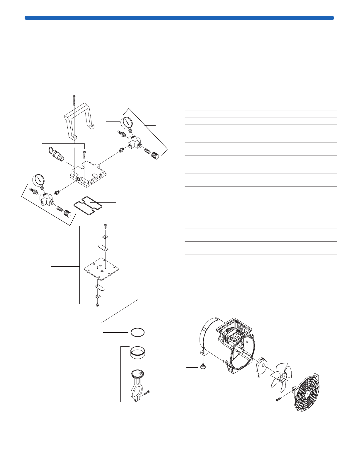
Maintenance
Under normal operating conditions, and using
proper handling procedures, the high-output
vacuum/pressure pump should provide many hours
of trouble-free operation.
The dry vacuum/pressure pumps are 100% oil-free.
The pump employs a non-lube piston and cylinder. No
maintenance is necessary for the bearings. All bearings
are sealed and permanently lubricated. Lubrication
should not be attempted. The units are built for
continuous duty operation with quietness
and durability.
CAUTION: Do not lubricate any of the parts with
oil, grease, or petroleum products. Do not clean with
acids, caustics, or chlorinated solvents. Do not replace
the connecting rod or motor bearings.
Disconnect the pump from power before
performing any maintenance.

P36512w REV 07/20 4 of 6
Troubleshooting
Vacuum Problems
Leakage, contamination, and unusual out-gassing are
the general causes of problems associated with poor
vacuum. To operate at maximum efficiency, a system
must be thoroughly clean. If the system is completely
clean and free from leaks, and unwarranted vacuum
problems still exist, the pump should be checked. A
simple criterion for the condition of the pump is the
determination of its maximum vacuum capability.
This can be accomplished by blocking the intake and
reading the vacuum level on the gauge.
Pressure Problems
Leakage and contamination are the general causes
of problems associated with poor pressure. To operate
at maximum efficiency, a system must be thoroughly
clean. If the system is completely clean and free
from leaks, and unwarranted pressure problems still
exist, the pump/compressor should be checked by
a service technician.
Troubleshooting Guide
Low
Flow
Low
Pressure
Unit Will
Not Start
Motor
Overheats
Loud
Unit Possible Cause Corrective Action
● ● ● Damaged valves Replace flapper valves
● ● ● Debris in valves Remove debris and check for
valve damage
● ● ● Worn diaphragm Replace diaphragm and/or liner
● ● ● Loose head screws Tighten head screws
● ● ● Bent motor shaft Replace entire unit
●Loose fittings Tighten fittings
●Insufficient ventilation
in enclosure
Increase air circulation
in enclosure
● ● Loose rod clamping screw Apply Loctite®242 and re-tighten
● ● ● Damaged O-rings Replace O-rings

P36512w REV 07/20 5 of 6
1
5
2
3
7
6
4
9
11
10
8
Repair
Three replacement part kits are available for the high output vacuum/pressure pump. The
accompanying drawing outlines the contents of each of the kits. We recommend trained service
technicians perform repairs. For further information or for help ordering the correct kit, please
contact Technical Service.
Disconnect the pump from power before performing any maintenance.
Key Description
Maintenance
Kit
(WP62MNT00)
Rebuild Kit
(115 V~)
(WP62RBDNA)
Rebuild Kit
(230 V~/100 V~)
(WP62RBDEU)
1Handle screws 2 2 2
2Head screws 4 4 4
3Head O-ring 1 1 1
4Pressure
regulator
assembly
— — —
5Pressure
gauge — 1 1
6Vacuum
regulator
assembly
— — —
7Vacuum
gauge — 1 1
8Valve plate
assembly
(includes
flapper [leaf]
valves)
— 1 1
9Cylinder
O-ring
1 1 1
10 Connecting
rod assembly* — 1 1
11 Rubber
suction feet
— — —
*The connecting rod assembly shipped with the rebuild kit for the
115 V~ pump is different from the one shipped with the rebuild kit for
the 230 V~ and 100 V~ pumps.

P36512w REV 07/20 6 of 6
The life science business of Merck operates
as MilliporeSigma in the U.S. and Canada.
Merck, Millipore, Millex and Sigma-Aldrich are trademarks of Merck KGaA, Darmstadt,
Germany or its affiliates. All other trademarks are the property of their respective
owners. Detailed information on trademarks is available via publicly accessible resources.
© 2021 Merck KGaA, Darmstadt, Germany and/or its affiliates. All Rights Reserved.
Specifications
Performance
Vacuum 27.2 inches of Hg (inHg)
Maximum Free
Air Displacement
34 L/min
Pressure 50 psi continuous,
80 psi intermittent
Sound Level Less than
60 dB(A)
Dimensions WP6211560
WP6222050,
WP6210060
Length 8.0 in. (20.3 cm) 7.3 in. (18.5 cm)
Width 9.0 in. (22.9 cm) 9.0 in. (22.9 cm)
Height 9.8 in. (24.9 cm) 10.2 in. (25.9 cm)
Weight (approximate) 11 lbs (5 kg) 14.5 lbs (6.6 kg)
Tubing Connectors Stepped 1⁄4in. hose barb
Materials of Construction
Body and pump head Die cast aluminum
Pump Type Piston with PTFE seal
Leaf valves High grade stainless steel
Electrical Specifications
115 V~, 60 Hz, 5.1 A
or
100 V~, 50/60 Hz,
4.1/2.7 A
Shaded-pole, single phase,
1⁄7HP motor 3-pronged, grounded
cord and plug
230 V~, 50 Hz, 1.1 A Permanent split capacitor, 1⁄3HP motor
HAR cordage, CEE 7/7 (Schuko)
Line voltage limits ± 10% of supply voltage
Environmental Conditions
Temperature 5 °C (41 °F) to 40 °C (104 °F)
Relative Humidity,
Maximum
80% for temperatures up to 31 °C,
decreasing to 50% at 40 °C
Altitude, Maximum 2000 meters
Pollution Degree 2, per IEC 664
(indoor usage: lab, office, etc.)
Installation Category II, per IEC 624
(local level: appliances,
portable equipment, etc.)
Product Ordering Information
Purchase products online at SigmaAldrich.com.
Catalogue
Number
High Output Vacuum/Pressure Pump
115 V~, 60 Hz WP6211560
230 V~, 50 Hz WP6222050
100 V~, 50/60 Hz WP6210060
Replacement Parts
Pump Maintenance Kit
WP62MNT00
Includes head O-ring,
cylinder O-ring, handle screws,
and head screws
Pump Rebuild Kit
Includes pressure gauge,
vacuum gauge, valve plate
assembly including flapper
valves, head O-ring,
cylinder O-ring, connecting
rod assembly, handle screws,
and head screws
115 V~
100 V~
230 V~
WP62RBDNA
WP62RBDEU
Millex®-FA50 filter unit, 10/pk SLFA05010
Pressure tubing, silicone, 25 ft XX8000025
Vacuum tubing, silicone, 4 ft XX7100004
Notice
We provide information and advice to our customers
on application technologies and regulatory matters
to the best of our knowledge and ability, but without
obligation or liability. Existing laws and regulations are
to be observed in all cases by our customers. This also
applies in respect to any rights of third parties. Our
information and advice do not relieve our customers of
their own responsibility for checking the suitability of
our products for the envisaged purpose.
The information in this document is subject to change
without notice and should not be construed as a
commitment by the manufacturing or selling entity, or
an affiliate. We assume no responsibility for any errors
that may appear in this document.
Contact Information
For the location of the office nearest you, go to
SigmaAldrich.com/offices.
Technical Assistance
Visit the tech service page on our web site at
SigmaAldrich.com/techservice.
Standard Warranty
The applicable warranty for the products listed in this
publication may be found at SigmaAldrich.com/terms.
This manual suits for next models
2
Table of contents
Other Merck Water Pump manuals
Popular Water Pump manuals by other brands

Truper
Truper PRE-1/3 manual

GORMAN-RUPP PUMPS
GORMAN-RUPP PUMPS 03F3-B Installation, operation, and maintenance manual with parts list

Sulzer
Sulzer ABS Coronada 250 Installation and operation manual

Graco
Graco 207321 Instructions-parts list

Grundfos
Grundfos AP40 Safety instructions and other important information

Gude
Gude GFP 5200 Translation of the original instructions