Merida ONE 60 User manual

ONE-SIXTY III
ONE-FORTY II
2022-10-28 V5

1
2
4
5
6
7
8
12
13
14
15
PAGE
We have put a lot of effort into the
development of the new ONE-SIXTY/
FORTY frame platform to give you the best
riding experience possible. To help you get
the most out of your bike, we have created
this setup and service guide. It contains all
the important settings and features in an
easy-to-understand format.
INTRODUCTION
SUSPENSION SETUP: FORK
SUSPENSION SETUP: SHOCK
SUSPENSION SETUP NOTES
WHEEL SIZE ADJUSTMENT
DROPPER SEATPOST ADJUSTMENT
COCKPIT HEIGHT / SERVICE PORT
STORAGE SOLUTIONS / ACCESSORIES
SPARE PARTS
GEOMETRIES
FRAME / SHOCK INTERFACES
EXPLODED DRAWINGS /
PARTS OVERVIEW
CONTENT

1
All suspension fork manufacturers provide
detailed guides which help you to find the
best setup. Since they know their products
best, we recommend using their fork
setup guides instead of creating our own
recommendations for the fork.
https://trailhead.
rockshox.com/en/
https://www.ride-
fox.com/ subhome.
php?m=bike#tuning
https://www.srsuntour.
com/en/service/
SUSPENSION FORK ROCKSHOX FOX SUSPENSION SR SUNTOUR
Correctly adjusting the suspension to
your weight is crucial to getting maximum
performance from your bike. A very
important part of this is setting up the
sag - this is the amount the suspension
compresses under your weight. While there
are several ways to measure sag, our team
prefers to measure the sag in the seated
riding position. This process is simple and
easier to replicate.
SETTING UP THE SUSPENSION

2
No matter how good the kinematics are,
the suspension will never perform at 100%
without the right settings. Therefore, we
offer a recommendation for the ideal shock
setting. The advantage of our described
sag measuring technique is that it’s easy to
repeat accurately and consistently.
We recommend 30% sag (negative travel)
with the following measurement method,
but it is only a reference value. Depending
on your riding style and your preferences,
the sag can differ, but 30% is the ideal
starting point.
Too much sag can make the bike feel
sluggish and unresponsive. Too little
sag will make the bike feel harsh, and
massively reduce the rear wheel grip and
control.
The following is our way of measuring the
correct sag, and all recommendations are
based on this approach. To keep the results
consistent, it is very important to always
follow the same method.
1. Adjust your preferred seat height
2. Turn the compression adjustments (if
available on your shock) to the fully
opened position.
3. Sit on the saddle with fully extended
seatpost travel. Carry all your clothing
and ride essentials you‘d normally
take on a ride. See the picture on the
previous page.
4. If necessary, hold the front brake but
not the rear brake
5. Stand up and bounce a little bit on your
bike, then sit down again
6. Push the O-rings on the shock all the
way towards the dust seal
7. Step down from the bike carefully. Avoid
moving the position of the O-ring!
8. Measure the distance from the dust seal
to the O-ring.
9. If necessary, adjust your air pressure to
achieve the preferred sag.
TOP TIP:
After each change of shock pressure, you
need to equalise the pressure between the
positive and negative air chamber. Slowly
compress the shock by pushing the saddle
down. You can hear the equalisation by the
noise of air whistling. Mostly it’s found at
the sag point.
Model
ONE-SIXTY
ONE-FORTY
Shock
stroke
65 mm
57.5 mm
Sag (30% of
shock stroke)
19.5 mm
17.3 mm
REAR SHOCK
30% SAG VALUES
RECOMMENDED METHOD OF
SAG MEASURMENT WITH AIR
SHOCKS

3
The ONE-SIXTY and ONE-FORTY models
are equipped mainly with shocks from the
RockShox Super Deluxe series. Therefore
we recommend the following air pressure
figures as a first starting point.
If you want to use the ONE-SIXTY with a
coil shock, we recommend the following
spring rates.
Most ONE-SIXTY/FORTY models are
equipped with shocks from the RockShox
Super Deluxe series. The rebound damping
is directly related to the air spring pressure
and needs to be adjusted after setting the
air pressure. Therefore we recommend the
following settings as a starting point.
Rider weight
(including all
essentials)
Rider weight
(including all
essentials) Rebound
(clicks from
fully closed)
Air pressure rear shock
RockShox Super Deluxe
ONE-SIXTY
Coil spring rate Air pressure
ONE-SIXTY ONE-FORTY
120 psi
140 psi
160 psi
180 psi
200 psi
225 psi
250 psi
300 Ibs
350 Ibs
400 Ibs
450 Ibs
500 Ibs
120 psi
140 psi
160 psi
180 psi
200 psi
220 psi
240 psi
260 psi
280 psi
50 kg
60 kg
70 kg
80 kg
90 kg
100 kg
110 kg
55 - 65 kg
65 -75 kg
75 - 85 kg
85 - 95 kg
95 -105 kg
12 (fully open)
11
9
8
6
5
3
1
0
145 psi
165 psi
185 psi
205 psi
225 psi
250 psi
275 psi
RECOMMENDED AIR
PRESSURES FOR ROCKSHOX
SUPER DELUXE SHOCKS
RECOMMENDED COIL
SPRING RATES FOR
COIL SHOCKS
REBOUND DAMPING

4
Experimenting with the suspension can
be fun! But modify only one variable at a
time and note the settings down accurately.
Always count the compression and rebound
clicks from the fully closed position.
Please note: Not all suspension units have
High-Speed and Low-Speed adjusters.
1
2
3
4
5
6
7
8
9
10
Setup Nr Pressure Compression Fork Rebound Fork
High
Speed
High
Speed
High
Speed
High
Speed
Fork
Low
Speed
Low
Speed
Low
Speed
Low
Speed X / 10
Compression Shock Rebound Shock Feeling
psi
psi
psi
psi
psi
psi
psi
psi
psi
psi
psi
psi
psi
psi
psi
psi
psi
psi
psi
psi
clicks
clicks
clicks
clicks
clicks
clicks
clicks
clicks
clicks
clicks
clicks
clicks
clicks
clicks
clicks
clicks
clicks
clicks
clicks
clicks
clicks
clicks
clicks
clicks
clicks
clicks
clicks
clicks
clicks
clicks
clicks
clicks
clicks
clicks
clicks
clicks
clicks
clicks
clicks
clicks
clicks
clicks
clicks
clicks
clicks
clicks
clicks
clicks
clicks
clicks
clicks
clicks
clicks
clicks
clicks
clicks
clicks
clicks
clicks
clicks
clicks
clicks
clicks
clicks
clicks
clicks
clicks
clicks
clicks
clicks
clicks
clicks
clicks
clicks
clicks
clicks
clicks
clicks
clicks
clicks
/ 10
/ 10
/ 10
/ 10
/ 10
/ 10
/ 10
/ 10
/10
/10
NOTES FOR YOUR
SUSPENSION SETTINGS
Pressure
Shock

5
1. Remove the rear wheel with the axle
lever
2. Remove the shock using 6 mm and 4
mm hex keys
3. Loosen the outer bolts of the seatstay (A)
four turns. Tap these bolt heads lightly
with a hammer to ensure the flipchip
(B) loosens from its conical seat. Now
unscrew the bolts completely.
1. Slightly compress the rear triangle to
get access to the flipchip. Remove and
twist both flip chips inside the rocker.
The line on the flipchip must be aligned
with the line of the desired wheel size
on the rocker.
We know that both rear wheel sizes (27.5”
for mullet and 29”) have pros and cons.
Therefore, we have designed a system
that works with both rear wheel sizes
via a simple adjustment that leaves the
important geometry data such as reach,
stack and angles untouched.
29” wheels are faster, have better rollover
behaviour and are ideal for taller people.
But thanks to the 27.5“ rear wheel and
corresponding 4 mm shorter chainstay
length, the mullet set-up with the 27.5”
rear wheel is more playful and forgiving.
The greater bum clearance will especially
suit small riders on steep terrain.
4.
Assemble the screws (A) again. Make
sure to refit the washers in between
the flipchip and the seatstay bearing.
Tighten the screws (A) with their
imprinted torque by using a torque
wrench.
Mount the shock again with its
imprinted torque by using a torque
wrench.
WHEEL SIZE
ADJUSTMENT
CHANGE THE REAR
WHEEL SIZE
A
A
B
B
5.
6.
Please note that your tyre pressure has
also a massive impact on your riding.
Go and check the SRAM tyre pressure
guide:
https://axs.sram.com/guides/tire/pressure

6
Watch our video how-to guide below:
https://www.youtube.com/watch?v=Uh-
mexL63b64
On the carbon frames, it is possible to
mount an Eightpins seatpost.
Eightpins Online Shop:
https://www.eightpins.com/en/eightpins-
seatposts-for-merida-bikes/
1.
1.
2.
3.
4.
5.
6.
7.
8.
9. Using a hex key (2.5 mm), turn the
screw (C) anticlockwise (-) until the
orange rope stops moving, as observed
through the viewing window.
10. Close flap (A) and tighten screw (B) with
a 2.5 mm hex key.
1. Loosen screw (B) with a 2.5 mm hex
key and open the flap (A) downwards.
1. Loosen screw (B) with a 2.5 mm hex
key and open the flap (A) downwards.
2. Apply pressure to the saddle with your
hand and press the remote to allow the
saddle to extend slowly to full travel.
3. Close flap (A) and tighten screw (B) with
a 2.5 mm hex key.
1. Press the remote lever to open the valve
and lower the seatpost with the rider‘s
weight to the desired maximum
extension position.
MERIDA TEAM TR DROPPER
SEATPOST ADJUSTMENT
EIGHTPINS SEATPOST
MAXIMUM TRAVEL LIMITATION
3.
4.
2.
B
A
C
USAGE OF COMPLETE TRAVEL

7
EAN: 4057094015126
EAN: 4057094032901
EAN: 4057094032918
EAN: 4057094033144
EAN: 4057094033137
You may have noticed that this bike has a
relatively short head tube across all sizes.
This is part of our the overall concept
because for smaller riders, it’s often very
complicated to lower their cockpit height, but
it’s easy to raise it up.
With 5 & 10 mm stem spacers and
different rise bars it is possible to increase
the cockpit height to your preferred height.
Sometimes regular maintenance is not
enough, and you need a new bearing kit or
a completely new headset. Just search for
your model in the ACROS headset finder:
https://acros-components.com/en/replace-
ment-headsets
To ensure hassle free cable routing, we have
built a service port into the frame.
You have easy access to the cable-carrying
liners in the downtube as well as to the
cable of the dropper seatpost. For easy cable
routing, start pushing the cable housing from
the back of the rear triangle to the service
port and then through the cable-carrying
liner up to the headtube.
COCKPIT HEIGHT MERIDA COCKPIT PARTS SERVICE PORT
40 mm
50 mm
EAN: 4057094026863
EAN: 4057094026870
MERIDA EXPERT TR handle bar
MERIDA TEAM TR handle bar
MERIDA EXPERT eTRII stem
MERIDA WIRE PORT stem spacers
20 mm rise, 780 mm wide
aluminium
20 mm rise, 800 mm wide
carbon
35 mm rise, 800 mm wide
carbon
5 mm height
10 mm height

8
Our service port also allows you to store
some emergency parts in the down tube
and we created the ESSENTIAL TOOL
WRAP to help keep these organised.
You can put some small parts, like a small
pump, a spare UDH hanger, a tubeless
tyre puncture repair kit, a spare chain quick
link, some inner tube patches, and a CO2
cartridge into the bag. It’s up to you, as long
as the package isn’t too bulky. You could
even think about a spare inner tube when
folded flat.
USING STORAGE SOLUTIONS
AND ACCESSORIES
MERIDA ESSENTIAL TOOL WRAP
EAN: 4057094033168
ONE-SIXTY / ONE-FORTY ESSENTIAL TOOL WRAP

9
For all tube mounts, we recommend
wrapping the strap as shown below:
Depending on your frame, you have several
possibilities to mount a tube or some other
accessories. On the carbon ONE-SIXTY and
ONE-FORTY frame the TUBE BASE PLATE
is located at the front shock mount.
But you can also attach the MERIDA TRAIL
MOUNT, which can carry a spare UDH
hanger, two 16g CO2 cartridges or a pump
and also a tube.
TUBE BASE PLATE / TRAIL MOUNT
EAN: 4057094030136
EAN: 4057094030112
MERIDA TUBE BASE PLATE /
TRAIL MOUNT PARTS
For carbon frame
For aluminium frame
carbon frame
aluminium frame
Item No. A2161000217
Item No. A2161000227
MERIDA TRAIL MOUNT w. strap
MERIDA TUBE BASE PLATE
standard w. strap
MERIDA TRAIL MOUNT compatible pump
40 mm & 64 mm
bottle cage
On the aluminium frames the TUBE BASE
PLATE is located on the top of the down
tube.

10
Our MERIDA TR rear axle lever can be used
to tighten the rear axle, but when removed,
it also works as a 6 mm and 4 mm hex key
which can be used to tighten many other
bolts on the bike.
To use the removable axle lever, pull the
lever out of the non-drivetrain side of the
bike. Then, to restore it, simply push it back
into the centre of the through axle.
All ONE-SIXTY and ONE-FORTY models
include a tool box and multitool below the
saddle. The V-MOUNT enables mounting
the tool box and mini tool.
The multitool includes the following tools:
o Hex key: 2/2.5/3/4/5/6/8 mm
o Screw driver: +/-
o Torx: T10/T25/T30
To use the multitool, open the flap on the
tool box and pull it out. To store it, just push it
back into the tool box and close the flap.
To remove the whole box from the
saddle, remove the tool from the box and
disassemble the flap from the box by pulling
it out. Unscrew the box from the V-MOUNT
by using a 3 mm hex key.
REMOVABLE AXLE LEVER V-MOUNT WITH INCLUDED
MULTI TOOL
EAN: 4057094024029
EAN: 4057094020809
EAN: 4057094020793
With 6 mm / 4 mm
hex key
12-in-1
For installation below
the saddle
MERIDA removable axle lever
MERIDA Mini Tool
Mini Tool V-Mount Box

11
The ONE-SIXTY/ONE-FORTY is equipped
with two fender options. The short mudguard
protects the shock, seat tube and bearings
from dirt and stone chips. We recommend
that you always leave the short fender
mounted. Additionally, it has the function of
holding the chainstay protector in place.
If you are riding muddier trails, there is the
option of an additional long fender. This
complements the short fender and offers
significantly more protection against mud
and water.
1. Remove the rear wheel
2. Attach the long fender to the seat stays.
3. Put the long screws (A) through the seat
stay bridge of the frame, and tighten
them to 4 Nm.
4.
5.
6.
7.
8.
9.
10.
11.
12.
13.
14.
15.
16.
17.
18.
19. Screw the short bolts (B) into the inside
of the seat stays and tighten them to
max. 2 Nm. We recommend the use of
some medium strength thread-locking
fluid.
20. Reinstall the rear wheel and double-
check that there is enough clearance for
contact-free rotation.
INSTALLING THE DIFFERENT
FENDERS
MOUNTING THE LONG FENDER
EAN: TBAFor ONE-SIXTY /
ONE-FORTY
Long Fender
4.
5.
A
B
12
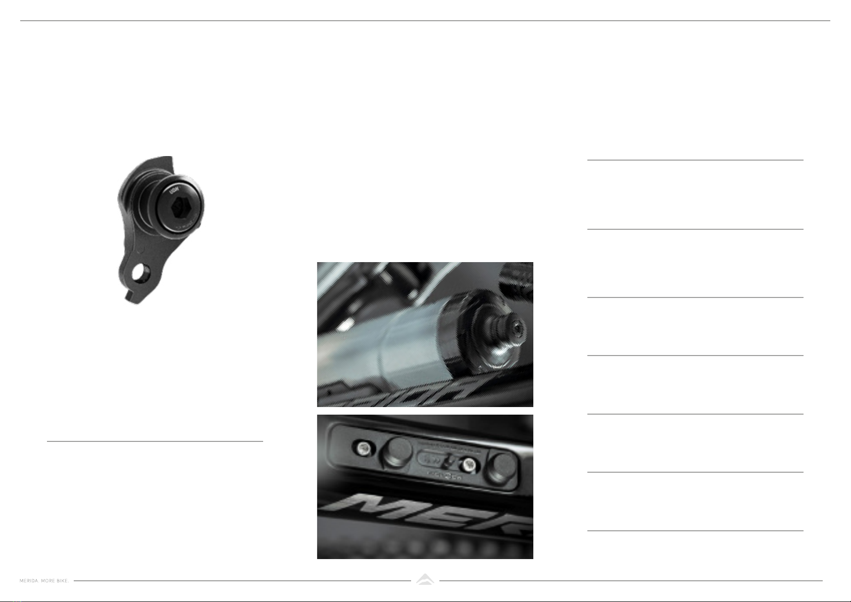
The SRAM universal derailleur hanger is
used across many bike brands. In the event
of a failure, this means that a replacement
hanger should be easily available in shops
worldwide.
The carbon frames have a recess for the
integrated FIDLOCK mount to give it a flush
finish. They also come as stock with the
integrated magnetic base. Aluminium models
can use the standard base.
If you don’t want to use the integrated base,
it’s possible to mount a standard bottle cage.
Some cages will not fit properly into the recess.
To fill that space, and allow all cages to be
fitted, we have designed a specific cover plate.
A bottle comes with the twist bottle
connector, but can be purchased without the
connector as well.
SRAM UNIVERSAL DERAILLEUR
HANGER (UDH)
SWIVEL MAGNETIC BOTTLE
EAN: 710845840135SRAM part number:
00.7918.089.000
SRAM UDH
SPARE PARTS
EAN: 4057094033212
EAN: 4057094033229
EAN: 4057094033236
EAN: 4057094033243
EAN: 4057094033250
EAN: TBA
EAN: 4057094033205
MERIDA SWIVEL bottle, transparent
MERIDA SWIVEL bottle, matt black
MERIDA SWIVEL bottle, transparent
MERIDA SWIVEL bottle, matt black
MERIDA SWIVEL bottle, matt black
MERIDA cover plate for SWIVEL ‘base up‘
0.6 l, with connector and
standard base
0.6 l, with connector
0.6 l, with connector
0.6 l
0.6 l
Fidlock part number:
F9617-000102(BLK)
MERIDA SWIVEL bottle, matt black
0.6 l, with connector and
standard base

13
ONE-SIXTY CF4 III
FS frame Size XShort Short Mid Long XLong
TS tyre Size 2 9 "/ 2 7. 5 " 2 9 "/ 2 7. 5 " 2 9 "/ 2 7. 5 " 29"/29" 29"/29"
ST seat tube [mm] 400 410 425 445 470
TT top tube [mm] 535 562 589 621 653
CS chain stay length [mm] 434 434 434 438 438
HTA head tube angle [°] 64 64 64 64 64
STA seat tube angle [°] 79 79 79 79 79
BD bottom bracket drop [mm] 7 7 7 2 7. 5 2 7. 5
HT head tube [mm] 95 95 95 105 120
FL fork length [mm] 581 581 581 581 581
Rreach [mm] 415 442 470 498 525
Sstack [mm] 615 615 615 625 638
WB wheel base [mm] 1188 1215 1242 1275 1308
SH stand over height [mm] 727 730 737 736 776
ONE-SIXTY LITE III
FS frame Size XShort Short Mid Long XLong
TS tyre Size 2 9 "/ 2 7. 5 " 2 9 "/ 2 7. 5 " 2 9 "/ 2 7. 5 " 29"/29" 29"/29"
ST seat tube [mm] 400 410 425 445 470
TT top tube [mm] 535 562 589 621 653
CS chain stay length [mm] 434 434 434 438 438
HTA head tube angle [°] 64 64 64 64 64
STA seat tube angle [°] 79 79 79 79 79
BD bottom bracket drop [mm] 7 7 7 2 7. 5 2 7. 5
HT head tube [mm] 95 95 95 105 120
FL fork length [mm] 581 581 581 581 581
Rreach [mm] 415 442 470 498 525
Sstack [mm] 615 615 615 625 638
WB wheel base [mm] 1188 1215 1242 1275 1308
SH stand over height [mm] 735 740 743 740 735
WB
CS
BD
S
ST SH
STA H TA
R
FL
HT
TT
ONE-FORTY CF4 III
FS frame Size XShort Short Mid Long XLong
TS tyre Size 29"/29" 29"/29" 29"/29" 29"/29" 29"/29"
ST seat tube [mm] 400 410 425 445 470
TT top tube [mm] 532 559 586 618 649
CS chain stay length [mm] 4 3 7. 5 4 3 7. 5 4 3 7. 5 4 3 7. 5 4 3 7. 5
HTA head tube angle [°] 65 65 65 65 65
STA seat tube angle [°] 80 80 80 80 80
BD bottom bracket drop [mm] 35 35 35 35 35
HT head tube [mm] 95 95 95 105 120
FL fork length [mm] 557 557 557 557 557
Rreach [mm] 426 453 480 509 535
Sstack [mm] 607 607 607 616 629
WB wheel base [mm] 1177 1204 1232 1265 1298
SH stand over height [mm] 722 725 732 731 771
ONE-FORTY LITE III
FS frame Size XShort Short Mid Long XLong
TS tyre Size 29"/29" 29"/29" 29"/29" 29"/29" 29"/29"
ST seat tube [mm] 400 410 425 445 470
TT top tube [mm] 532 559 586 618 649
CS chain stay length [mm] 4 3 7. 5 4 3 7. 5 4 3 7. 5 4 3 7. 5 4 3 7. 5
HTA head tube angle [°] 65 65 65 65 65
STA seat tube angle [°] 80 80 80 80 80
BD bottom bracket drop [mm] 35 35 35 35 35
HT head tube [mm] 95 95 95 105 120
FL fork length [mm] 557 557 557 557 557
Rreach [mm] 426 453 480 509 535
Sstack [mm] 607 607 607 616 629
WB wheel base [mm] 1177 1204 1232 1265 1298
SH stand over height [mm] 730 735 738 735 730
GEOMETRIES

14
* Frame weight only! Without axle, frame protectors, saddle clamp, hanger, steerer cups and cable guides
(weight is also depending on the frame color)
ONE-FORTY / ONE-SIXTY CF4 III LITE III
MA X. WHEELSIZE 29x2.5" 29x2.5"
MAX. CHAINRING 1x34T 1x34T
CHAINLINE 55mm 55mm
HEAD TUBE
1 1/2” & 1 1/2” • •
HEADSET
WIRE PORT IS • •
BRAKE STANDARD
DISC BRAKE ABOVE SEAT STAY (W CUSTOM ADAPTER) • •
POST MOUNT 200MM REAR BRAKE • •
MAX. REAR BRAKE ROTOR SIZE 220mm 220mm
BB-STANDARD
BSA 73MM (W 2.5MM ISCG05-PLATE) • •
SEATPOST DIAMETER
34.9 MM • •
REAR DROPOUT-STANDARD
THRU AXLE 12X148MM • •
CABLE ROUTING
INTERNAL SHIFTING CABLES • •
INTERNAL BRAKE CABLE • •
INTERNAL SEAT POST CABLE • •
ISCG 05 • •
FD-STANDARD 1x specific 1x specific
FRAME WEIGHT 2460g in size M +/- 3% 3660g in size M +/- 3%
RD HANGER SRAM UDH SRAM UDH
ONE-FORTY CF4 III LITE III
SHOCK
LENGTHXSTROKE (MM) 2 3 0 x 5 7. 5 2 3 0 x 5 7. 5
REAR TRIANGLE EYELET
PIN WIDTH (MM) W/O ANY BUSHING W/O ANY BUSHING
FRONT TRIANGLE EYELET
PIN WIDTH (MM) 30 30
PIN ID (MM) 10 10
COILSHOCK READY -- --
RECOMMENDED SAG 30% 30%
ONE-SIXTY CF4 III LITE III
SHOCK
LENGTHxSTROKE (MM) 230x65 230x65
REAR TRIANGLE EYELET
PIN WIDTH (MM) W/O ANY BUSHING W/O ANY BUSHING
FRONT TRIANGLE EYELET
PIN WIDTH (MM) 30 30
PIN ID (MM) 10 10
COILSHOCK READY -- --
RECOMMENDED SAG 30% 30%
FRAME INTERFACES SHOCK INTERFACES

15
910 11 12 12 11 10 9
14 15 10
10 15 14
11 11
19 18
17 16
26
33
34
11
23
24
20
3
4
7
8
13
41
41
41
42
45
45 45
44
40 39
37
36 35
38
44
46
43
25
25
30
28
6
27
32 29
5
5
1
2
22
21
30
29
32
47
47
47
47
48
49
49
50
51
31
A
A
B
C
C
B
D
D
EE
CARBON FRAME
EXPLODED VIEW
Can be purchased through your local
MERIDA dealer using the Item No.
No. Item No. Item Detail information Pieces Torque
Nm
1A2161000217 MOUNT for tube/accessories 1
2A2300000612 SCREW M8x1.25 L6mm 18~10
3A2300000471 BOLT M6x1 OD10mm L39mm 1 10~12
4A2294000196 WASHER for M6 sunkenhead screw OD16mm 1
5A2298000113 SCREW M6x1 L16mm 26~8
6A2292000102 WASHER OD19mm ID15mm H0.3mm 1
7A2300000608 SCREW M8x1 110~12
8A2036000025 MOUNT for shock without bushing 1
9A2300000611 SCREW M15x1 L18.5mm 213~15
10 A2221000033 BEARING 6803V-2RS OD26mm ID17mm W5mm 4
11 A2294000102 WASHER OD21mm ID17.1mm H3mm 5
12 A2302000082 NUT M15x1 flip chip 2
13 A2031000076 LINK 1
14 A2300000610 SCREW M15x1 L16mm 213~15
15 A2294000182 LOCK RING for bearing 2
16 A2300000475 BOLT M6x1 OD10/12mm L55mm 1 8~10
17 A2221000032 BEARING 6801V-2RS OD21mm ID12mm W5mm 1
18 A2221000034 BEARING 6800V-2RS OD19mm ID10mm W5mm 1
19 A2294000197 WASHER for M6 sunkenhead screw OD18.5mm 1
20 A2161000161 COVER for service opening 1
21 A2294000183 LOCK RING for protector screw 1
22 A2300000559 SCREW M5x0.8 L11mm 13~5
23 A2294000105 WASHER OD17mm ID12.1mm H2mm 1
24 A2294000085 WASHER OD15.5mm ID10.1mm H2mm 1
25 A2143000147 BLIND PLUG 2
26 A2294000016 WASHER OD19mm ID15.1mm H3mm 1
27 A2300000484 SCREW M4x0.7 L10mm 11,5~2
28 A2232000028 CHAIN GUIDE for 28T-36T 1
29 A2292000106 WASHER OD10mm ID6.2mm H0.5mm 2
30 A2298000224 SCREW M6x1 L16mm 26~8
31 A2232000042 MOUNT Mount for chain guide 1
32 A2292000008 WASHER OD10mm ID6.2mm H3mm 2
33 A2298000107 SCREW M6x1 L12mm 16~8
34 A2164000062 MOUNT ISCG-05 1
35 A2161000162 CABLE GUIDE 1
36 A2300000151 SCREW M4x0.7 L12mm 13~5
37 A2300000598 BOLT M6x1 OD15/17mm L55mm 18~10
38 A2221000040 BEARING 172607V-2RS OD26mm ID17mm W7mm 1
39 A2221000043 BEARING 3802V-2RS OD24mm ID15mm W7mm 1
40 A2300000609 SCREW M10x1 L15mm 18~10
41 A2300000318 SCREW M4x0.7 L12mm 33~5
42 A2116000239 PROTECTOR 1
43 A2158000078 PROTECTOR for chain stay 1
44 A2311000102 RD-HANGER UDH 1
45 A2298000223 SCREW M6x1 L12mm 36~8
46 A2136000076 MOUNT PM200 1
47 A2191000188 HEAD SET MERIDA/VP-8151 (MH-P16/MH-P16) 1
48 A2358000131 PROTECTOR for down tube 1
49 A2298000024 SCREW M5x0.8 L10mm 24~6
50 A2362000105 PROTECTOR for seat stay 1
51 A2002000135 THRU AXLE EXPERT TR; L=178.5mm M12x1
T L= 1 3 . 5 m m 1

16
17 8
718 18 7
817
10 98
8910
77
15 14
13 16
22 7
11
12
1
2
4
6
19
26 25
23
24
21 20
5
3
3
A
A
B
C
C
B
D
D
E
E
D
ALUMINIUM FRAME
SUSPENSION HARDWARE
Can be purchased through your local
MERIDA dealer using the Item No.
No. Item No. Item Detail information Pieces Torque
Nm
1A2300000471 BOLT M6x1 OD10mm L39mm 1 10~12
2A2294000196 WASHER for M6 sunkenhead screw OD16mm 1
3A2298000113 SCREW M6x1 L16mm 26~8
4A2300000608 SCREW M8x1 110~12
5A2292000102 WASHER OD19mm ID15mm H0.3mm 1
6A2036000025 MOUNT for shock without bushing 1
7A2294000102 WASHER OD21mm ID17.1mm H3mm 5
8A2221000033 BEARING 6803V-2RS OD26mm ID17mm W5mm 4
9A2294000182 LOCK RING for bearing 2
10 A2300000610 SCREW M15x1 L16mm 213~15
11 A2294000105 WASHER OD17mm ID12.1mm H2mm 1
12 A2294000085 WASHER OD15.5mm ID10.1mm H2mm 1
13 A2221000032 BEARING 6801V-2RS OD21mm ID12mm W5mm 1
14 A2221000034 BEARING 6800V-2RS OD19mm ID10mm W5mm 1
15 A2294000197 WASHER for M6 sunkenhead screw OD18.5mm 1
16 A2300000475 BOLT M6x1 OD10/12mm L55mm 1 8~10
17 A2300000611 SCREW M15x1 L18.5mm 213~15
18 A2302000082 NUT M15x1 flipchip 2
19 A2031000076 LINK 1
20 A2161000162 CABLE GUIDE 1
21 A2300000151 SCREW M4x0.7 L12mm 13~5
22 A2294000016 WASHER OD19mm ID15.1mm H3mm 1
23 A2300000598 BOLT M6x1 OD15/17mm L55mm 18~10
24 A2221000040 BEARING 172607V-2RS OD26mm ID17mm W7mm 1
25 A2221000043 BEARING 3802V-2RS OD24mm ID15mm W7mm 1
26 A2300000609 SCREW M10x1 L15mm 18~10
27 A2311000102 RD-HANGER UDH 1

17
27 27
4
5
15
14
18
1
2
3
3
19
17
17
17
16
6
7
13
13
10
11
8
8
12
12
20
20
20
20
9
21
22
23
3
3
24
26
25
20
ALUMINIUM FRAME
SMALL PARTS
Can be purchased through your local
MERIDA dealer using the Item No.
No. Item No. Item Detail information Pieces Torque
Nm
1A21610000211 CABLE GUIDE for headtube 1
2A2161000227 MOUNT for tube/accesoires 1
3A2298000004 SCREW M5x0.8 L15mm 48~10
4A2161000079 COVER for service opening 1
5A2300000231 SCREW M3x0.5 L8mm 1
6A2164000062 MOUNT ISCG-05 1
7A2298000107 SCREW M6x1 L12mm 16~8
8A2292000008 WASHER OD10mm ID6.2mm H3mm 2
9A2232000042 MOUNT Mount for chain guide 1
10 A2232000028 CHAIN GUIDE for 28T-36T 1
11 A2300000484 SCREW M4x0.7 L10mm 11,5~2
12 A2292000106 WASHER OD10mm ID6.2mm H0.5mm 2
13 A2298000224 SCREW M6x1 L16mm 26~8
14 A2116000239 PROTECTOR 1
15 A2300000318 SCREW M4x0.7 L12mm 33~5
16 A2136000076 MOUNT PM200 1
17 A2298000223 SCREW M6x1 L12mm 36~8
18 A2158000078 PROTECTOR for chain stay 1
19 A2258000079 CABLE PLUG for brake 1
20 A2191000185 HEAD SET MERIDA/VP-8158 (MH-P16/MH-P16) 1
21 A2358000131 PROTECTOR for down tube 1
22 A2358000132 PROTECTOR for down tube 1
23 A2362000121 PROTECTOR for seat stay 1
24 A2002000135 THRU AXLE EXPERT TR; L=178.5mm M12x1
T L= 1 3 . 5 m m 1
25 A2029000034 TUBE foam; ID5mm L600mm 2
26 A2029000042 TUBE foam; ID6mm L600mm 1
Other manuals for ONE 60
1
This manual suits for next models
1
Table of contents
Other Merida Bicycle manuals


Popular Bicycle manuals by other brands


Circe Cycles
Circe Cycles Helios owner's manual

Specialized
Specialized S-WORKS SL2 Instruction guide

Worksman
Worksman PORTOTRIKE PT, PORTOTRIKE PT2F, PORTOTRIKE PTCB, PORTOTRIKE PT2CB, PORTOTRIKE... owner's manual

Ariel Rider
Ariel Rider Ebikes X-Class manual

GT
GT Street Machine GT Service instructions

YBIKE
YBIKE SESSION owner's manual


