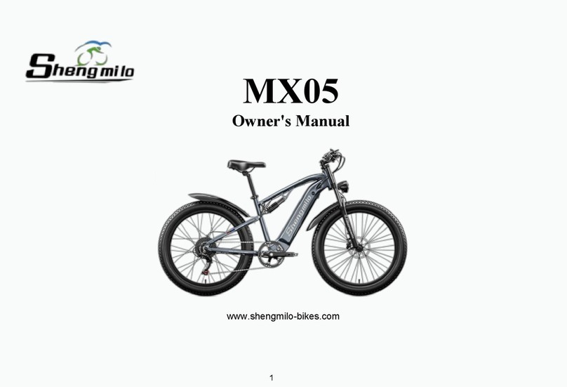
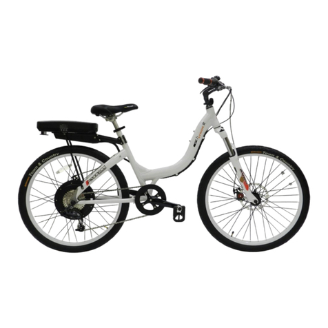
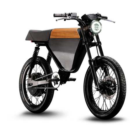
Merida PowerCycle User manual


MERIDA USERS MANUAL Page 1
Section 1 - INTRODUCTION
A. About This Manual . . . . . . . . . . . . . . . . . . . . . . . . . . 2
B. Important Notices . . . . . . . . . . . . . . . . . . . . . . . . . . . 2
C. General Warning’s . . . . . . . . . . . . . . . . . . . . . . . . . . . 2
D. A Special Note To Parents . . . . . . . . . . . . . . . . . . . . 2
Section 2 - BASIC INSTRUCTIONS
A. What it is called . . . . . . . . . . . . . . . . . . . . . . . . . . . . . 3
B. Bike Fit . . . . . . . . . . . . . . . . . . . . . . . . . . . . . . . . . . . . . . 3
C. Safety First . . . . . . . . . . . . . . . . . . . . . . . . . . . . . . . . . . 3
D. Mechanical Safety Check . . . . . . . . . . . . . . . . . . . . 4
E. Before Your First Ride . . . . . . . . . . . . . . . . . . . . . . . . 4
F. First Ride . . . . . . . . . . . . . . . . . . . . . . . . . . . . . . . . . . . . 4
G. Riding An Electric Bike . . . . . . . . . . . . . . . . . . . . . . 5
Section 3 - SAFETY
A. The Basics . . . . . . . . . . . . . . . . . . . . . . . . . . . . . . . . . . . 5
B. Riding Safety . . . . . . . . . . . . . . . . . . . . . . . . . . . . . . . . 5
C. Off Road Safety . . . . . . . . . . . . . . . . . . . . . . . . . . . . . 6
D. Wet Weather Riding . . . . . . . . . . . . . . . . . . . . . . . . . 6
E. Night Riding . . . . . . . . . . . . . . . . . . . . . . . . . . . . . . . . 6
F.
Changing Components or Adding Accessories . .
7
Section 4 - FIT
A. Standover Height . . . . . . . . . . . . . . . . . . . . . . . . . . . 7
B. Saddle Position . . . . . . . . . . . . . . . . . . . . . . . . . . . . . 7
C. Handlebar Height And Angle . . . . . . . . . . . . . . . . 8
D. Control Position Adjustments . . . . . . . . . . . . . . . . 8
E. Brake Reach . . . . . . . . . . . . . . . . . . . . . . . . . . . . . . . . . 8
Section 5 - HOWTHINGSWORK
A. Right Hand Controls . . . . . . . . . . . . . . . . . . . . . . . . . 9
B. Left Hand Controls . . . . . . . . . . . . . . . . . . . . . . . . . 10
C. Power Assist . . . . . . . . . . . . . . . . . . . . . . . . . . . . . . .10
D. Wheels . . . . . . . . . . . . . . . . . . . . . . . . . . . . . . . . . . . . . 10
E. Brakes . . . . . . . . . . . . . . . . . . . . . . . . . . . . . . . . . . . . .12
F. Seat Post Quick Release . . . . . . . . . . . . . . . . . . . . 14
G. Bicycle Suspension . . . . . . . . . . . . . . . . . . . . . . . . .15
H. Pedals . . . . . . . . . . . . . . . . . . . . . . . . . . . . . . . . . . . . .16
I. Tires and Tubes . . . . . . . . . . . . . . . . . . . . . . . . . . . . 16
J. Lighting System . . . . . . . . . . . . . . . . . . . . . . . . . . . . 17
Section 6 - BATTERY MANAGEMENT
A. Battery Warnings . . . . . . . . . . . . . . . . . . . . . . . . . . . 18
B. Prior To Charging . . . . . . . . . . . . . . . . . . . . . . . . . . . 18
C. Charging Instructions . . . . . . . . . . . . . . . . . . . . . . 19
D. Charger LED’s . . . . . . . . . . . . . . . . . . . . . . . . . . . . . . 19
E. Charge Times . . . . . . . . . . . . . . . . . . . . . . . . . . . . . .20
F. Power On/Off Key Switch . . . . . . . . . . . . . . . . . . . 20
G. Battery Level Indicator . . . . . . . . . . . . . . . . . . . . . 20
H. Battery Pack Installation And Removal . . . . . . 21
I. Battery Pack Storage . . . . . . . . . . . . . . . . . . . . . . . 22
J. Transporting Your Bike . . . . . . . . . . . . . . . . . . . . .22
K. Battery Care And Maintenance . . . . . . . . . . . . . 22
L. Battery Disposal . . . . . . . . . . . . . . . . . . . . . . . . . . . .23
M.Replacement Program . . . . . . . . . . . . . . . . . . . . . 23
Section 7 - BICYCLE CARE & MAINTAINANCE
A. Service Intervals . . . . . . . . . . . . . . . . . . . . . . . . . . . . 23
B. If Your Bicycle Sustains An Impact . . . . . . . . . . 24
C. Electric Components . . . . . . . . . . . . . . . . . . . . . . .24
D. Cleaning . . . . . . . . . . . . . . . . . . . . . . . . . . . . . . . . . . . 24
Section 8 - IMPORTANT STUFF
A. Contacting EWI . . . . . . . . . . . . . . . . . . . . . . . . . . . . 25
B. Limited Warranty . . . . . . . . . . . . . . . . . . . . . . . . . . . 25
C. Warranty Registration Card . . . . . . . . . . . . . . . . . 25
D. Recording Your Date of Purchase . . . . . . . . . . . 25
E. Recording Your Serial & Model Number . . . . . 25
F. Recording Your Key Number . . . . . . . . . . . . . . . . 26
G. Battery Exchange Program . . . . . . . . . . . . . . . . . 26
H. Recording Your Dealer Information . . . . . . . . . 26
I. Specifications . . . . . . . . . . . . . . . . . . . . . . . . . . . . . . 26
J. Notes . . . . . . . . . . . . . . . . . . . . . . . . . . . . . . . . . . . . . . 27
TableOf Contents
MERIDAPowerCycle™

Page 2 MERIDA USERS MANUAL
1.INTRODUCTION
Congratulations on the purchase of your new MERIDA
PowerCycle™. Your bicycle is a high quality, environmen-
tally friendly electric vehicle.This manual will provide you
with the information needed to operate, maintain and en-
joy it safely.Your new bicycle should provide you with years
of healthy enjoyment provided you follow these steps.
For technical questions or customer service please contact
Electric Wheels International at (408) 270-3724 or e-mail
1a.ABOUTTHIS MANUAL
To prevent serious injury to yourself and others,and to pre-
vent damage to the bike please read and understand these
instructions completely before operating your
PowerCycle™.Your new PowerCycle™ is a powerful,reliable
electric bicycle.You should use caution and care while get-
ting used to your bikes riding characteristics. The follow-
ing manual will provide basic instructions regarding your
bicycles care and maintenance, battery management, op-
erating procedures, and other important information.You
should read it thoroughly before riding your bike. If you
have questions that aren’t answered in this manual con-
tact your local authorized MERIDA dealer or call Electric
Wheels International at 408.270.3724.
1b.IMPORTANT NOTICES
•Make sure your bike is properly fitted to you as
described in section 2b.
•Perform the mechanical safety check described in
section 2d before each ride.
•Ensure the charger voltage switch, on the end of the
charger, is set to the correct position: 115V for U.S.A.
or 230V for most European countries.
•Please read the battery pack and charging instructions
before charging the battery pack.
•If you haven’t already done so, fully charge your
battery according to the charging instructions.
•Always fully recharge the battery pack after each ride.
•Always store the battery pack in a cool and dry place.
•During periods of prolonged storage,the battery pack
should be charged at least once every 2 months.
•Although your MERIDA PowerCycle™ can be ridden as
a standard bicycle, it is strongly recommended that
you do not ride without the battery pack in place as it
may affect performance.
1c.GENERALWARNING
Like any sport, bicycling involves risk of injury and damage.
By choosing to ride a bicycle, you assume the responsibility
for that risk, so you need to know — and to practice — the
rules of safe and responsible riding and of proper use and
maintenance. Proper use and maintenance of your bicycle
reduces risk of injury.
This Manual contains many “Warnings” and “Cautions”
concerning the consequences of failure to maintain or
inspect your bicycle and of failure to follow safe cycling
practices.
The word WARNING indicates a potentially hazardous
situation that, if not avoided, could result in serious
injury or death.
The word CAUTION indicates a potentially hazardous
situation, which, if not avoided, may result in minor or
moderate injury, serious, damage to the bicycle or the
voiding of your warranty or is an alert against unsafe
practices.
Many of the Warnings and Cautions say, “you may lose
control and fall.” Because any fall can result in serious
injury or even death, we do not always repeat the warn-
ing of possible injury or death. Because it is impossible
to anticipate every situation or condition that can oc-
cur while riding, this Manual makes no representation
about the safe use of the bicycle under all conditions.
There are risks associated with the use of any bicycle
which cannot be predicted or avoided, and which are
the sole responsibility of the rider.
1d.A SPECIAL NOTETO PARENTS
The MERIDA PowerCycle™ is intended for use by adult rid-
ers only. As a parent or guardian, you are responsible for
the activities and safety of your minor child.That includes,
making sure that your minor child can safely ride and con-
trol all of the operations of the bicycle, and fully under-
stands all warnings as indicated in this User Manual.
Please read on if you have determined that your minor child
can safely ride and control all of the operations of the bi-
cycle. That includes making sure that the bicycle is prop-
erly fitted to the child; that it is in good repair and safe op-
erating condition;that you and your child have learned and
understand the safe operation of the bicycle; and that you
and your child have learned,understand and obey not only
the applicable local motor vehicle, bicycle and traffic laws,
MERIDA PowerCycle™
OPERATIONAL INSTRUCTIONS

MERIDA USERS MANUAL Page 3
but also the common sense rules of safe and responsible
bicycling. As a parent or guardian, you should read and
understand this manual. Before letting any child ride the
PowerCycle™,review with them all warnings as well as the
information on the proper usage of your battery pack,
charger and bicycle.
WARNING: Make sure that your child always wears
an approved bicycle helmet when riding; but also make
sure that your child understands that a bicycle helmet is
for bicycling only,and must be removed when not riding.
A helmet must not be worn while playing, in play areas,
on playground equipment,while climbing trees,or at any
time while not riding a bicycle. Failure to follow this
warning could result in serious injury or death.
be able to adjust their angle and reach.See Section 4e and
5e for details.
6. Do you fully understand how to operate your new bi-
cycle? If not,before your first ride,have your dealer explain
any functions or features that you do not understand.
2c.SAFETY FIRST
1.Always wear an approved helmet when riding your bike,
and follow the helmet manufacturer’s instructions for fit,
use and care of your helmet.
2. Do you have all the other required and recommended
safety equipment? See Section 3. It’s your responsibility to
familiarize yourself with the laws of the areas where you
ride, and to comply with all applicable laws.
3. Do you know how to correctly operate your wheel axle
2b.BIKE FIT
1.Is your bike the right size? To check, see Section 4.If your
bicycle is too large or too small for you, you may lose con-
trol and fall. If your new bike is not the right size, ask your
dealer to exchange it before you ride it.
2. Is the saddle at the right height? To check, see Section
4b.If you adjust your saddle height,make sure that you fol-
low the Minimum Insertion instructions.
3. Are saddle and seat post securely clamped? A correctly
tightened saddle will allow no saddle movement in any
direction. See section 5f for details.
4.Are the stem and handlebars at the right height for you?
If not, see section 4c on what you can do about it.
5.Can you comfortably operate the brakes? If not,you may
Battery
Level
Indicator
Bell
Front
Chain
Ring
Rear Hub
Rear Cog
Rear Wheel Drive Chain
Tail Light
Fenders
Handle Bars
Stem
Head tube
Basket
(500 only)
Fork
Front Brake
Frame
Headlight
Support
Stand
Twist Shift Levers
Brake Levers
Grips,
Crank Arm Pedals Key Switch
Motor Housing Front Wheel
Saddle
Seat post
Seat
Post QR
Rear Rack
Battery
Pack
2.BASIC INSTRUCTIONS
2a.WHAT IT IS CALLED

Page 4 MERIDA USERS MANUAL
and handlebar stem are parallel to the bike’s center line
and clamped tight enough so that you can’t twist them out
of alignment. If not, align and tighten them.
6.Handlebar ends: Make sure the handlebar grips are se-
cure and in good condition.If not,replace them.Make sure
the handlebar ends and extensions are plugged.If not,plug
them before you ride. If the handlebars have bar end ex-
tensions,make sure they are clamped tight enough so you
can’t twist them. If not, tighten them.
7.BatteryPackAttachment:Ensure your battery pack is firmly
attached to your bicycle before riding. To test battery at-
tachment,pull up on the battery pack handle after battery
is locked in place. If attached properly you will be able to
lift the bike off the ground.If not,the battery pack will come
off the bike.
8. Generator Powered Light: Verify your front generator
mounting bolt is tight prior to riding to ensure light does
not interfere with your wheels.
WARNING: Loose or damaged handlebar grips or
extensions can cause you to lose control and fall.
Unplugged handlebars or extensions can cut your body,
and can cause serious injury in an otherwise minor
accident.
2e.BEFOREYOUR FIRST RIDE
Before your first ride study this manual. Then make sure
you fully charge your battery with the appropriate charger.
Be sure to firmly attach the battery to the bicycle. Lift the
bike off the ground by the battery handle to ensure proper
installation.
2f.FIRST RIDE
When you buckle on your helmet and go for your first fa-
miliarization ride on your new bicycle,be sure to pick a con-
trolled environment, away from cars, other cyclists, ob-
stacles or other hazards. Ride to become familiar with the
controls,features and performance of your new bike.
1. Familiarize yourself with the braking action of the bike.
Test the brakes at slow speed, putting your weight toward
the rear and gently applying the brakes, rear brake first.
Sudden or excessive application of the front brake could
pitch you over the handlebars. Applying brakes too hard
can lock up a wheel, which could cause you to lose control
and fall (see section 5e).
2. If your bicycle has toe clips or clipless pedals, practice
getting in and out of the pedals.
3.If your bike has suspension,familiarize yourself with how
the suspension responds to brake application and rider
weight shifts.
nuts? Check Section 5 to make sure.Riding with an improp-
erly adjusted wheel quick release or axle nut can cause the
wheel to wobble or disengage from the bicycle, and cause
serious injury or death.
5.Does your bike have suspension? Suspension can change
the way a bicycle performs. Follow the suspension
manufacturer’s instructions for use, adjustment and care.
6. Do you have “toe overlap”? On smaller framed bicycles
your toe or toe clip may be able to contact the front wheel
when a pedal is all the way forward and the wheel is turned.
2d.MECHANICAL SAFETY CHECK
Check the condition of your bicycle before every ride.
1.Nuts,boltsandstraps:Make sure nothing is loose. Lift the
front wheel off the ground by two or three inches then let
it bounce on the ground.Anything sound,feel or look loose?
Do a quick visual and tactile inspection of the whole bike.
Any loose parts or accessories? If so,secure them.If you’re
not sure, ask someone with experience to check.
2.TiresandWheels:Make sure tires are correctly inflated (see
section 5i). Check by putting one hand on the saddle, one
on the intersection of the handlebars and stem, then
bouncing your weight on the bike while looking at tire
deflection. Compare what you see with how it looks when
you know the tires are correctly inflated; and adjust if nec-
essary. Tires in good shape? Spin each wheel slowly and
look for cuts in the tread and sidewall. Replace damaged
tires before riding the bike.Wheels true? Spin each wheel
and check for brake clearance and side-to-side wobble.If a
wheel wobbles side to side even slightly, or rubs against or
hits the brake pads, take the bike to a qualified bike shop
to have the wheel trued.
CAUTION: Wheels must be true for the brakes to work
effectively. Wheel truing is a skill that requires special
tools and experience. Do not attempt to true a wheel
unless you have the knowledge, experience and tools
needed to do the job correctly.
3.Brakes: Check the brakes for proper operation. Squeeze
the brake levers. Are the brake quick-releases closed? All
control cables seated and securely engaged? Do the brake
pads touch the wheel rim within an inch of brake lever
movement? Can you apply full braking force at the levers
without having them touch the handlebar? If not, your
brakes need adjustment. Do not ride the bike until the
brakes are properly adjusted.
4.QuickReleases:Make sure seat post quick release is prop-
erly adjusted and in the locked position.
5.Handlebar and saddle alignment: Make sure the saddle

MERIDA USERS MANUAL Page 5
4.Practice shifting the gears.Remember to never move the
shifter while pedaling backward.
5. Check out the handling and response of the bike; and
check the comfort.
6. If you have any questions, or if you feel anything about
the bike is not as it should be, take the bike back to your
dealer for advice.
2g.RIDING AN ELECTRIC BIKE
Riding an electric bike is similar to riding a non-electric bike
but there are some differences to note. An electric bike is
heavier and requires more time to stop (see section 5e for
information on braking).Your bike is also equipped with a
powerful motor that provides a boost most noticeable
when starting from a stop,riding uphill or into a headwind.
The assist tapers off at approximately 15 mph.The boost is
exhilarating, but you must be comfortable with the sensa-
tion before riding in crowded or congested areas.To maxi-
mize battery life pedal faster, to maximize boost pedal
slower.Your battery is a finite resource and proper mainte-
nance will prolong its performance and usability.
CAUTION:The bike will accelerate rapidly from a stand
still. Also, the motor will continue to drive the bike for 3
seconds after you stop pedaling. Leave extra room for
all starts and stops.
3.SAFETY
3a.THE BASICS
1. Always wear a cycling helmet,
which meets the latest certification
standards. Follow the helmet
manufacturer’s instructions for fit,use
and care of your helmet.Most serious
bicycle injuries involve head injuries
that might have been avoided if the
rider had worn a helmet.
WARNING: Failure to wear a
helmet when riding may result in
serious injury or death.
2. Always do the Mechanical Safety Check (Section 2d)
before you get on a bike.
3. Be thoroughly familiar with the controls of your bicycle:
brakes (Section 5e), pedals (Section 5h) and shifting (Sec-
tion 5a)
4.Be careful to keep body parts and other objects away from
the sharp teeth of chainrings; the moving chain;the turning
pedals and cranks; and the spinning wheels of your bicycle.
5. Always wear:
•Shoes that will stay on your feet and will grip the ped-
als. Never ride barefoot or while wearing sandals.
•Bright,visible clothing that is not so loose that it can be
tangled in the bicycle or snagged by objects at the side
of the road or trail.
• Protective eyewear, to protect against airborne dirt, dust
and bugs — tinted when the sun is bright, clear when it’s
not.
6. Don’t jump with your bike.Jumping a bike,particularly a
BMX or mountain bike, can be fun; but it puts incredible
stress on everything from your spokes to your pedals. Rid-
ers who insist on jumping their bikes risk serious damage,
to their bicycles as well as to themselves.
7. Ride at a speed appropriate for conditions. Increased
speed means higher risk.
3b.RIDING SAFETY
1. Observe all local bicycle laws and regulations. Observe
regulations about licensing of bicycles,riding on sidewalks,
laws regulating bike path and trail use, and so on. Observe
helmet laws, child carrier laws and special bicycle traffic
laws. It’s your responsibility to know and obey the laws.
2.You are sharing the road or the path with others — mo-
torists, pedestrians and other cyclists. Respect their rights.
3. Ride defensively. Always assume that others do not see
you.
4. Look ahead, and be ready to avoid:
•Vehicles slowing or turning, entering the road or your
lane ahead of you, or coming up behind you.
•Parked car doors opening.
•Pedestrians stepping out.
•Children or pets playing near the road.
•Pot holes,sewer grating,railroad tracks,expansion joints,
road or sidewalk construction,debris and other obstruc-
tions that could cause you to swerve into traffic, catch
your wheel or otherwise cause you to lose control and
have an accident.
•The many other hazards and distractions which can
occur on a bicycle ride.
5. Ride in designated bike lanes,on designated bike paths
or as close to the edge of the road as possible.
6. Stop at stop signs and traffic lights; slow down and look
both ways at street intersections.Remember that a bicycle
always loses in a collision with a motor vehicle; so be pre-
pared to yield even if you have the right of way.
7. Use approved hand signals for turning and stopping.
8. Never ride with headphones. They mask traffic sounds
and emergency vehicle sirens, distract you from concen-

Page 6 MERIDA USERS MANUAL
trating on what’s going on around you,and their wires can
tangle in the moving parts of the bicycle, causing you to
lose control.
9.Never carry a passenger, unless it is a small child wearing
an approved helmet and secured in a correctly mounted
child carrier or a child-carrying trailer.
10.Never carry anything which obstructs your vision or your
complete control of the bicycle, or which could become
entangled in the moving parts of the bicycle.
11. Never hitch a ride by holding on to another vehicle.
12. Don’t do stunts, wheelies or jumps.They can cause you
injury and damage your bike.
13. Don’t weave through traffic or make any moves that
may surprise people with whom you are sharing the road.
14. Observe and yield the right of way.
15. Never ride your bicycle while under the influence of al-
cohol or drugs.
16. If possible, avoid riding in bad weather, when visibility
is obscured,at dusk or in the dark,or when extremely tired.
Each of these conditions increases the risk of accident.
3c.OFF ROAD SAFETY
WARNING: This bike is not designed for off road use.
3d.WETWEATHER RIDING
Under wet conditions, the stopping power of your brakes
(as well as the brakes of other vehicles sharing the road) is
dramatically reduced and your tires don’t grip nearly as well.
This makes it harder to control speed and easier to lose
control. To make sure that you can slow down and stop
safely in wet conditions, ride more slowly and apply your
brakes earlier and more gradually than you would under
normal, dry conditions (see section 5e).
WARNING: Wet weather impairs traction, braking and
visibility, both for the bicyclist and for other vehicles
sharing the road. The risk of an accident is dramatically
increased in wet conditions.
3e.NIGHT RIDING
Riding a bicycle at night is many times more dangerous than
riding during the day. A bicyclist is very difficult for motor-
ists and pedestrians to see.Therefore,children should never
ride at dawn, at dusk or at night. Adults should not ride at
dawn, at dusk or at night unless it is absolutely necessary.
Bicycle reflectors are designed to pick up and reflect
streetlights and car lights in a way that may help you
to beseen and recognized as a moving bicyclist.
WARNING: Reflectors are not a substitute for required
lights.Riding at dawn, at dusk,at night or at other times
of poor visibility without an adequate bicycle lighting
system and without reflectors is dangerous and may
result in serious injury or death.
CAUTION: Check reflectors and their mounting
brackets regularly to make sure that they are clean,
straight, unbroken and securely mounted. Have your
dealer replace damaged reflectors and straighten or
tighten any that are bent or loose.
WARNING: Do not remove the front or rear reflectors
or reflector brackets from your bicycle. They are an
integral part of the bicycle’s safety system.
WARNING: Removing the reflectors may reduce your
visibility to others using the roadway. Being struck by
other vehicles may result in serious injury or death.
WARNING: The reflector brackets may protect you
from the brake straddle cable catching on the tire in the
event of brake cable failure. If a brake straddle cable
catches on the tire, it can cause the wheel to stop
suddenly, causing you to loose control and fall.
If you must ride under conditions of poor visibility, check
and be sure you comply with all local laws about night
riding, and take the following strongly recommended ad-
ditional precautions:
•Make sure that your bicycle is equipped with correctly
positioned and securely mounted reflectors.
•Make sure that your generator powered head and tail-
lights meet all regulatory requirements and provide ad-
equate visibility.
•Wear light colored, reflective clothing and accessories,
such as a reflective vest, reflective arm and leg bands,
reflective stripes on your helmet, flashing lights ... any
reflective device or light source that moves will help you
get the attention of approaching motorists, pedestri-
ans and other traffic.
•Make sure your clothing or anything you may be carry-
ing on the bicycle does not obstruct a reflector or light.
While riding at dawn, at dusk or at night:
•Ride slowly.
•Avoid dark areas and areas of heavy or fast-moving
traffic.
•Avoid road hazards.
•If possible, ride on familiar routes.

MERIDA USERS MANUAL Page 7
3f.CHANGING COMPONENTS OR ADDING
ACCESSORIES
There are many components and accessories available to
enhance the comfort,performance and appearance of your
bicycle.However, if you change components or add acces-
sories, you do so at your own risk. The bicycle’s manufac-
turer may not have tested that component or accessory
for compatibility, reliability or safety on your bicycle. Be-
fore installing any component or accessory,including a dif-
ferent size tire, make sure that it is compatible with your
bicycle by checking with your dealer. Be sure to read, un-
derstand and follow the instructions that accompany the
products you purchase for your bicycle.
WARNING: Failure to confirm compatibility, properly
install, operate and maintain any component or
accessory can result in serious injury or death.
CAUTION: Changing the
components on your bike may void
the warranty. Refer to your
warranty, and check with your
dealer before changing the
components on your bike.
4.FIT
Make sure the bike fits. A
bike that’s too big or too
small is harder to control
and can be uncomfort-
able.
NOTE:
Correct fit is an essential element of bicycling safety, per-
formance and comfort.Making the adjustments to your bi-
cycle that results in correct fit for your body and riding con-
ditions requires experience, skill and special tools. Always
have your dealer make the adjustments on your bicycle;or,
if you have the experience,skill and tools, have your dealer
check your work before riding.
WARNING: If your bicycle does not fit properly, you
may lose control and fall.If your new bike doesn’t fit,ask
your dealer to exchange it before you ride it.
4a.STAND OVER HEIGHT
Stand over height is the basic element of bike fit.
It is the distance from the ground to the top of the bicycle’s
imaginary top tube at that point where your crotch would
be if you were straddling the bike and standing half way
between the saddle and the handlebars.To check for cor-
rect stand over height,straddle the bike while wearing the
kind of shoes in which you’ll be riding, and bounce vigor-
ously on your heels. If your crotch appears to touch the
imaginary top tube, the bike is too big for you. Don’t even
ride the bike around the block.A bike that you ride only on
paved surfaces and never take off-road should give you a
minimum stand over height clearance of five centimeters.
A bike that you’ll ride on unpaved surfaces should give you
a minimum of seven and a half centimeters of stand over
height clearance.
4b.SADDLE
POSITION
Correct saddle adjust-
ment is an important
factor in getting the most
performance and comfort
from your bicycle. If the saddle
position is not comfortable for you,see
your dealer,who has the tools and skill to
change it.
The saddle can be adjusted in three direc-
tions (figure 1):
1. Up and down adjustment (Figure 1A). To check for cor-
rect saddle height:
•Sit on the saddle
•Place one heel on a pedal
•Rotate the crank until the pedal with your heel on it is
in the down position and the crank arm is parallel to the
seat tube.
If your leg is not completely straight and
just touching the center of the pedal,
your saddle height needs to be ad-
justed.If your hips must rock for
the heel to reach the pedal,
the saddle is too high. If
your leg is bent at the
knee with your heel on
the pedal, the saddle is
too low.
Once the saddle is at the correct
height, make sure that the seat
post does not project from the
frame beyond its“Minimum In-
sertion” or “Maximum Exten-
sion” mark. If you can read the
markings on the seat post - go
see your MERIDA Dealer.
Figure 1B
Figure 1C
Figure 1A

Page 8 MERIDA USERS MANUAL
WARNING: If your seat post projects from the frame
beyond the Minimum Insertion or Maximum Extension
mark,the seat post may break,which could cause you to
lose control and fall.
2. Front and back adjustment (Figure 1B). The saddle can
be adjusted forward or back to help you get the optimal
position on the bike. Ask your dealer to set the saddle for
your optimal riding position and to show you how to make
further adjustments.
3. Saddle angle adjustment (Figure 1C). Most people pre-
fer a horizontal saddle;but some riders like the saddle nose
angled up or down just a little.Your dealer can adjust saddle
angle or teach you how to do it.
Small changes in saddle position can have a substantial
effect on performance and comfort. Only one directional
change at a time,and only a small change at a time, should
be made to your saddle position.
WARNING: After any saddle adjustment, be sure that
the saddle adjusting mechanism is properly tightened
before riding. A loose saddle clamp or seat post binder
can cause damage to the seat post, or can cause you to
lose control and fall. A correctly tightened saddle
adjusting mechanism will allow no saddle movement in
any direction. Periodically check to make sure that the
saddle adjusting mechanism is properly tightened.
If, in spite of carefully adjusting the saddle height,tilt and
fore-and-aft position, your saddle is still uncomfortable,
you may need a different saddle design. Saddles, like
people, come in many different shapes, sizes and resil-
ience. Your dealer can help you select a saddle which,
when correctly adjusted for your body and riding style,
will be comfortable.
WARNING: Some people have claimed that extended
riding with a saddle which is incorrectly adjusted or
which does not support your pelvic area correctly can
cause short-term or long-term injury to nerves and blood
vessels, or even impotence. If your saddle causes you
pain, numbness or other discomfort, see your dealer.
4c.HANDLEBAR HEIGHT AND ANGLE
Your bike is equipped either with a “threadless” stem (550
LTD), which clamps on to the outside of the steerer tube, or
with a“quill”stem (500/550),which clamps inside the steerer
tube by way of an expanding binder bolt.If you aren’t abso-
lutely sure which type of stem your bike has,ask your dealer.
If your bike has a“threadless”stem, your dealer may be able
to change handlebar height by adjusting the stem angle or
moving height adjustment spacers from below the stem to
above the stem, or vice versa. Consult your dealer. Do not
attempt to do this yourself,as it requires special knowledge.
If your bike has a “quill” stem, you can ask your dealer to
adjust the handlebar height a bit by adjusting the stem
angle or stem height. Consult your dealer. Do not attempt
to do this yourself, as it requires special knowledge.
A quill stem has an etched or stamped mark on its shaft which
designates the stem’s “Minimum Insertion” or “Maximum
extension”. This mark must not be visible above the headset.
Your dealer can also change the angle of the handlebar or
add bar end extensions. If these adjustments do not help,
you’ll have to get a stem of different length or rise.
WARNING: On some bicycles, changing the stem or
stem height can affect the tension of the front brake
cable, locking the front brake or creating excess cable
slack that can make the front brake inoperable. If the
front brake pads move in towards the wheel rim or out
away from the wheel rim when the stem or stem height
is changed,the brakes must be correctly adjusted before
you ride the bicycle.
WARNING: The stem’s Minimum Insertion Mark must
not be visible above the top of the headset. If the stem is
extended beyond the Minimum Insertion Mark the stem
may break or damage the fork’s steerer tube,which could
cause you to lose control and fall.
WARNING: An insufficiently tightened stem binder
bolt, handlebar binder bolt or bar end extension
clamping bolt may compromise steering action, which
could cause you to lose control and fall. Place the front
wheel of the bicycle between your legs and attempt to
twist the handlebar/stem assembly. If you can twist the
stem in relation to the front wheel, turn the handlebars
in relation to the stem, or turn the bar end extensions in
relation to the handlebar, the bolts are insufficiently
tightened.
4d.CONTROL POSITION ADJUSTMENTS
The angle of the controls and their position on the handle-
bars can be changed. Ask your dealer to make the adjust-
ments for you.
4e.BRAKE REACH
Your PowerCycle™ has brake levers that can be adjusted
for reach. If you have small hands or find it difficult to
squeeze the brake levers, your dealer can either adjust the
reach or fit shorter reach brake levers.
WARNING: The shorter the brake lever reach, the
more critical it is to have correctly adjusted brakes, so
that full braking power can be applied within available
brake lever travel. Brake lever travel insufficient to apply
full braking power can result in loss of control,which may
result in serious injury or death.

MERIDA USERS MANUAL Page 9
5.HOWTHINGSWORK
5a.RIGHT HAND CONTROLS
Rear brake
Squeezing the right brake lever (figure 2A) actuates the rear
brake. See the braking section of this manual for impor-
tant information on brake usage before riding your bike.
Twist grip gear selector
The PowerCycle™ uses a Shimano Nexus twist grip (figure
2B & 3B) to shift gears. The 4 speed gears are part of the
rear internal gear hub. The indicator on the shifter body
(figure 2C & 3C) points to the selected gear.
How an internal gear hub drivetrain works:
Your bicycle has an internal gear hub drivetrain, the gear
changing mechanism will consist of:
•4speed internal gear hub
•One twist grip shifter
•One control cable
•One front chainring
•Adrive chain
•Arear cog
Shifting internal gear hub gears
Shifting with an internal gear hub drivetrain is simply a mat-
ter of moving the shifter to the indicated position for the
desired gear. After you have moved the shifter to the gear
position of your choice,ease the pressure on the pedals for
an instant to allow the hub to complete the shift.
Which gear should I be in?
The numerically lowest gear (1) is for the steepest hills.
The numerically largest gear (4) is for the greatest speed.
Shifting from an easier,“slower” gear (like 1) to a harder,
“faster”gear (like 2 or 3) is called an upshift. Shifting from
a harder,“faster”gear to an easier,“slower” gear is called a
downshift. It is not necessary to shift gears in sequence.
Instead,find the“starting gear”for the conditions — a gear
which is hard enough for quick acceleration but easy
enough to let you start from a stop without wobbling —
and experiment with upshifting and downshifting to get
a feel for the different gears.At first,practice shifting where
there are no obstacles,hazards or other traffic,until you’ve
built up your confidence.If you have difficulties with shift-
ing, the problem could be mechanical adjustment. See
your dealer for help.
To shift to a higher gear, twist the shifter rearward (coun-
terclockwise when viewed from the right side).To shift to
a lower gear, twist the shifter forward (clockwise when
viewed from the right side.) For example, you can down-
shift to a lower gear to make pedaling easier on a hill.
On the other hand,you may up shift to a higher gear
when you wish to go faster. When downshifting,
stop pedaling, operate the shifter to select the
desired gear, and then resume pedaling. The Nexus
system on your PowerCycle™ downshifts only if you are
not pedaling.
When you are going uphill you will need to stop pedaling
and pause 2-3 seconds (allowing the motor to cut out) be-
fore shifting the gears. In general, on flat ground, use 2nd
or 3rd gear when starting from a complete stop. Shift to
3rd or 4th gear to increase your speed on flat ground. Use
4th gear when going downhill. When starting uphill, shift
the bike into 1st gear to avoid undue stress on the motor.
For more information on the shift mechanism,please study
the Shimano brochure that came with your bike, contact
your PowerCycle™ dealer or call Shimano American Cor-
poration @ 949-951-5003 (M-F, 8:00 am– 5:00 pm).
CAUTION: Starting uphill in any gear other then 1st
gear will put tremendous stress on the motor and battery
causing excessive battery drain and potential damage.
Recommended gear usage:
•1st gear – for starting uphill and climbing hills
Figure 2
Figure 3
A
B
C
E
F
D
D - Front Brake Lever
E- Bell
F - Bell Thumb Hammer
A - Rear Brake Lever
B - Twist Grip Shifter
C - Gear Selector
B
C

Page 10 MERIDA USERS MANUAL
5d.WHEELS
It is sometimes necessary to remove either your front or
rear wheel for storage or to change a tire & tube.
WARNING: Riding with improperly adjusted wheel
retention nuts can allow the wheel to wobble or
disengage from the bicycle, causing serious injury or
death to the rider. Therefore, it is essential that you:
1. Ask your dealer to help you make sure you know how
to install and remove your wheels safely.
2. Understand and apply the correct technique for
securing your wheel in place with axle nuts.
3. Each time, before you ride the bike, check that the
wheel is securely clamped.
Removing a bolt on front wheel
1. Release the front brake as described in section 5E.
2. With a 15-mm box wrench,loosen the two axle nuts (fig-
ure 5A & 5B).
3. If your front fork has a clip-on type secondary retention
device,disengage it and go to the next step.If your front
fork has an integral secondary retention device,loosen
the axle nuts enough to allow wheel removal; then go
to the next step.
4. Raise the front wheel a few inches off the ground and
tap the top of the wheel with the palm of your hand to
knock the wheel out of the fork ends.
Installing a bolt on front wheel
1. With the steering fork facing forward, insert the wheel
between the fork blades so that the axle seats firmly at
the top of the slots,which are at the tips of the fork blades.
The axle nut washers should be on the outside,between
the fork blade and the axle nut.If your bike has a clip-on
type secondary retention device,engage it.
2. While pushing the wheel firmly to the top of the slots
in the fork dropouts, and at the same time centering
the wheel rim in the fork, use a 15-mm box wrench
to tighten the axle nuts as tight as you can. (figure 5A
& 5B).
•2nd gear – for starting on flat terrain or riding into a
headwind
•3rd gear – for normal everyday riding
•4th gear – for flat terrain and riding downhill
•3rd & 4th gear - not recommended for going uphill.
5b.LEFT HAND CONTROLS
Front brake
Squeezing the left brake lever (figure 2D) actuates the front
brake. See the braking section of this manual for impor-
tant information on brake usage before riding your bike.
Bell
Use the bell (figure 2E) to alert people who may not see
you.Press down on the thumb hammer and release.Note:
the thumb hammer (figure 2F) rotates to allow position-
ing it for your comfort.
5c.POWER ASSIST
Your PowerCycle™ is a pedal assist bike.That is, the motor
supplies additional power to the rear wheel while you are
pedaling.A computerized sensor measures both speed and
torque to determine the amount of assist to provide. The
assist is most noticeable when starting from a stop, riding
into a headwind or climbing hills.
The motor automatically shuts off when: your speed ex-
ceeds approximately 15 mph, your pedaling cadence ex-
ceeds 62 rpm,(2-3 seconds) after you stop pedaling or bat-
tery voltage is low. The Battery must be fully charged with
the Key Switch set to “ON” for the Electric Power Assist to
function.
To engage Electric Power Assist
1. Install a fully charged battery.
2. Leave plenty of room for take
off.
3. Turn the Power Mode Switch
to the“ON”position (figure 4).
4. Climb onto your MERIDA
PowerCycle™
5. As you begin pedaling, Electric Power Assist will auto-
matically engage.You will hear the motor turn on and
feel a sudden surge as if someone is pushing you along.
6. To attain higher or lower speeds, shift the rear hub into
a lower or higher gear as described in the “Right Hand
Controls Section”.
7. To maintain power assist pedal below 15 mph and/or
62 rpm.
8. To maximize range turn off battery pack or pedal above
15 mph and/or 62 rpm.
FIGURE 4
A
B
FIGURE 5

MERIDA USERS MANUAL Page 11
3. Re-engage the front brake as described in section 5E to
restore correct brake pad-to-rim clearance; spin the
wheel to make sure that it is centered in the frame and
clears the brake pads;then squeeze the brake lever and
make sure that the brakes are operating correctly.
Removing a bolt on rear wheel
1. Stabilize the bike using its support stand.
2. Shift the PowerCycle™ into (#1) first gear.
3. With a #2 Philips screwdriver and 8-mm box wrench,
loosen and remove the rear brake arm retainer screw
and nut (figure 6,A).
4. With a 15-mm box wrench, loosen the axle nut (figure
7A) on each side of the bike, and pull the silver washer
(figure 7B) and each retainer washer (figure 7C) out from
the dropout.
5. Push the wheel forward until the axle comes out of the
rear dropouts. If necessary, deflate the tire slightly so it
will not hit the frame cross member behind the bottom
bracket.
6. Remove the shifter cable from the retainer (figure 6B)
on the inside of the right chain stay.
7. Note how the shift cable is routed through the guides
on the shift arm (Figure 8B). The cable will have to be
rerouted along the same path during assembly.
8. Rotate the shift arm (figure 8C) counterclockwise until
it stops.
Figure 6
Figure 7
Figure 8
A
A B C
C
D
E
Figure 9A Figure 9B
9. Use needle nose pliers to pull the inner cable fixing bolt
assembly (figure 8D) down past the flats of the shift arm
linkage and disconnect the pinch bolt assembly from
the shift arm.
10. Remove the chain from the rear sprocket (figure 8E).
11. With a 17-mm box wrench, loosen the brake housing
retainer nut (figure 9A),remove the nut and brake hous-
ing from the axle.(figure 9B)
12. Remove the wheel from the frame.If necessary, deflate
the tire completely so it will not hit the frame cross mem-
ber behind the bottom bracket.
Installing a bolt on rear wheel
1. Stabilize the bike using its support stand.
2. Fit the wheel into place between the chain stays.
3. Put the brake housing onto the hub and chain on the
rear sprocket. If necessary, deflate the tire completely
so it will not hit the frame cross member behind the
bottom bracket.
4. Replace the 17-mm brake housing retainer nut (figure
9A) and tighten with a box wrench.
5. Rotate the shift arm counterclockwise until it stops.
A B C CA
CB
B
A
B

Page 12 MERIDA USERS MANUAL
6. Turn the cable fixing bolt assembly so the flats on the
cable-fixing bolt align with the flats on the shift arm link-
age, and press the cable fixing bolt assembly up into
the linkage. (figure 8D)
7. Be sure the shift cable is properly routed through the
shift arm guides, (figure 8B) and release the shift arm.
8. Pull the rear wheel rearward so the axle slides into the
rear dropouts.Each retainer washer (figure 7C) must sit
between the axle nut and frame, and the tab on each
washer must engage the inside of its dropout (figure
6C).The black washer goes on the right (drive side) and
the gray washer (figure 6C) goes on the left (non- drive)
side of the frame.
9. Replace the silver washer (figure 7B) on the drive side.
10.Replace the two-axel nuts (figure 7A) and rotate several
turns by hand.
11. Pull the wheel rearward until the chain is taut. Center
the wheel between the two stays. Use a 15mm wrench
to tighten each axle nut to 350-500 kg-cm (25-36 ft.-
lb.).Alternate between left and right side as you tighten
the nuts to assure proper alignment.
12. Press the shift cable (figure 6B) into its retainer on the
right chain stay.
13. Attach the rear brake arm and replace the retainer arm
screw and nut (figure 6A).Tighten the screw with a #2
Phillips screwdriver while holding the nut with a 8mm
box wrench.
14. Spin the wheel. Be sure the wheel is centered in the
frame and that it clears the stay.
15.Test the function of the rear brake and gear shifter be-
fore riding the bike.
How brakes work
It’s important to your safety that you instinctively know
which brake lever controls, which brake. On your
PowerCycle™ the left brake lever controls the front brake.
The right brake lever controls the rear brake.
The braking action of a PowerCycle™ is a function in the
rear of the rollers on the disc or in the front of the brake
pads and the wheel rim.To make sure that you have maxi-
mum friction available: In the front you must keep your
wheel rim and brake pads clean and free of lubricants,
waxes or polishes. In the rear you must keep your brake
properly lubricated. See your MERIDA Dealer for more in-
formation on rear brake lubrication.
Make sure that your hands can reach and squeeze the brake
levers comfortably. If your hands are too small to operate
the levers comfortably, consult your dealer before riding
the PowerCycle™.The lever reach is adjustable (see section
on brake lever reach adjustment).
Brakes are designed to control your speed,not just to stop
the PowerCycle™. Maximum braking force for each wheel
occurs at the point just before the wheel locks up (stops
rotating) and starts to skid.Once the tire skids,you actually
lose most of your stopping force and all steering control.
You need to practice slowing and stopping smoothly with-
out locking up a wheel.The technique is called progressive
brake modulation.Instead of jerking the brake lever to the
position where you think you will generate appropriate
braking force, squeeze the lever, progressively increasing
the braking force. If you feel the wheel begin to lock up,
release pressure just a little to keep the wheel rotating just
short of lockup. It is important to develop a feel for the
amount of brake lever pressure required for each wheel at
different speeds and on different surfaces.To better under-
stand this,experiment a little by walking your PowerCycle™
and applying different amounts of pressure to each brake
lever until the wheel locks.
When you apply one or both brakes, the PowerCycle™
begins to slow, but your body wants to continue at the
speed at which it was going. This causes a transfer of
weight to the front wheel (or, under heavy braking,
around the front wheel hub, which could send you fly-
ing over the handlebars).
A wheel with more weight on it will accept greater brake
pressure before lockup; a wheel with less weight will lock
up with less brake pressure. So, as you apply brakes and
your weight shifts forward, you need to shift your body to-
ward the rear of the PowerCycle™, to transfer weight back
onto the rear wheel. At the same time, you need to both
5e.BRAKES
For most effective brak-
ing, use both brakes and
apply them simulta-
neously.
WARNING: Sudden or
excessive application of
the front brake may
pitch the rider over the
handle-bars, causing
serious injury or death.
CAUTION: PowerCycle™ brakes, such as direct pull
brakes(figure 10) and roller brakes(figure 11), are
extremely powerful. You should take extra care in
becoming familiar with these brakes and exercise
particular care when using them.
Figure 10

MERIDA USERS MANUAL Page 13
decrease rear braking and increase front braking force.This
is even more important on steep descents, because de-
scents shift weight forward.
Two keys to effective speed control and safe stopping are
controlling wheel lockup and weight transfer. This weight
transfer is even more pronounced if your bike has a front
suspension fork (550 LTD). Front suspension “dips” under
braking,increasing the weight transfer.Practice braking and
weight transfer techniques where there is no traffic or other
hazards and distractions.
Everything changes when you ride on loose surfaces or in
wet weather.Tire adhesion is reduced, so the wheels have
less cornering and braking traction and can lock up with
less brake force.Moisture or dirt on the brake pads reduces
their ability to grip. The way to maintain control on loose
or wet surfaces is to go more slowly to begin with.
Rear brake
Your PowerCycle™ is equipped with a Shimano Inter-M
Roller Brake (figure 11).You received a set of service instruc-
tions for the brake.Please refer to document #SI-4R35A for
detailed information regarding this brake.
In the case of #1 and #2, the cause might be not enough
brake grease, so ask your MERIDA Dealer to grease the
mechanism with special Shimano roller brake grease.
Brake cable free play adjustment (Rear
Roller Brake)
If the right brake lever fails the mechanical safety check,
restore brake lever travel by adjusting the brake lever free
play as described below.
1. Pull the brake lever to simulate a panic stop, and then
release the brake lever. Repeat this at least ten times.
This assures that all components are properly seated.
2. Pull the brake lever until it stops (Figure 12B).
3. The amount of lever travel from A to B should be 15
mm / 0.59 in. (figure 12).
Figure 11
WARNING: Hard-braking operation will cause the
internal brake parts to become very hot, and this may
weaken braking performance. It may also cause a
reduction in the amount of brake grease inside the brake,
and this can lead to problems such as abnormally sudden
braking.
If any of the following occur while using the brakes, stop
riding immediately and ask your MERIDA Dealer to carry
out inspection and repairs.
1. If abnormal noise is heard when the brakes are applied.
2. If braking force is abnormally strong.
3. If braking force is abnormally weak.
4. Loosen the adjuster locknut (figure 13, A), and turn
the barrel adjuster (figure 13, B) as necessary to adjust
clearance to within specification.(Turning the adjuster
out tightens the inner wire;turning the adjuster in loos-
ens the wire.) When the brake lever is within specifica-
tion, tighten the adjuster locknut.
Front brake release
The brake pads of the V-brakes can be quickly opened so
the pads can clear the tire when the wheel is removed or
installed.To open the front brake pads,perform the follow-
ing:
Figure 13
A B
Figure 12
15 mm A
B

Page 14 MERIDA USERS MANUAL
4. Loosen the adjuster locknut, (figure 13A) and turn the
barrel adjuster (figure 13B) as necessary to adjust clear-
ance to within specification. (Turning the adjuster out
tightens the inner wire; turning the adjuster in loosens
the wire.) When the brake lever is within specification,
tighten the adjuster locknut.
5. Squeeze the caliper arms together (figure 14A),and re-
move the cable guide from the bracket on the left cali-
per arm (figure 14B). The brake lever free play is prop-
erly adjusted if the cable guide can be easily removed
from the bracket.
6. If you cannot easily release the cable guide from the
bracket, perform the following:
a. Turn the adjusting barrel at the brake lever in (clock-
wise) one full turn.Try to remove the cable guide again.
b. If you still cannot release the cable guide, turn the ad-
justing barrel in an additional turn.
c. If the cable guide still does not release,loosen the pinch
bolt (figure 14C) and release 2-3 mm (0.079 - 0.118 in.)
of inner wire from the pinch mechanism.
d. Tighten pinch bolt (figure 14C).
e. Repeat the adjusting procedure.
5f.SEAT POST QUICK RELEASE
PowerCycle's™ are equipped with a quick-release seat post
binder. While a quick release looks like a long bolt with a
lever on one end and a nut on the other, the quick release
uses a cam action to firmly clamp the seat post (figure 16).
1. Squeeze the caliper arms together (figure 14A).
2. Disconnect the cable guide on the brake cable from the
bracket on the left caliper arm (figure 14D).
Once the wheel is reinstalled, close the brake pads by per-
forming the following:
1. Squeeze the caliper arms together (figure 14A).
2. Connect the cable guide to the bracket on the left cali-
per arm (figure 14B).
3. Test brake function before riding bike.
Brake cable free play adjustment (Front
Brake)
If the left brake lever fails the mechanical safety check, re-
store brake lever travel by adjusting the brake lever free
play as described below.
1. Pull the brake lever to simulate a panic stop, and then
release the brake lever. Repeat this at least ten times.
This assures that all components are properly seated.
2. Pull the brake lever until the brake pads just touch the
rim. Note lever position (Figure 15B).
3. The amount of lever travel from A to B should be 25
mm / 0.98 in. (figure 15).
Figure 14DFigure 14
Figure 15
WARNING: Riding with an improperly tightened seat
post can allow the saddle to turn or move and cause you
to lose control and fall. Therefore:
1. Ask your dealer to help you make sure you know how
to correctly clamp your seat post.
2. Understand and apply the correct technique for
clamping your seat post quick release.
3. Before you ride the bike, first check that the seat post
is securely clamped.
A B C
A
25 mm
D
Figure 16
Closed Position
A
B

MERIDA USERS MANUAL Page 15
Figure 17
Adjusting the seat post quick release
mechanism
The action of the quick release cam squeezes the seat col-
lar around the seat post to hold the seat post securely in
place. The tension-adjusting nut controls the amount of
clamping force.Turning the tension-adjusting nut clockwise
while keeping the cam lever from rotating increases clamp-
ing force, turning it counterclockwise while keeping the
cam lever from rotating reduces clamping force. Less than
half a turn of the tension-adjusting nut can make the dif-
ference between safe and unsafe clamping force.
WARNING: The full force of the cam action is needed
to clamp the seat post securely.Holding the nut with one
hand and turning the lever like a wing nut with the other
hand until everything is as tight as you can get it will not
clamp the seat post safely.
WARNING: If you can fully close the quick release
without wrapping your fingers around a frame tube for
leverage, and the lever does not leave a clear imprint in
the palm of your hand, the tension is insufficient. Open
the lever; turn the tension-adjusting nut clockwise a
quarter turn; then try again. Repeat until tight.
5g.BICYCLE SUSPENSION
Your bicycle has a suspension
system including a seat post (fig-
ure 18) & fork (550 LTD Only) (fig-
ure 17). Be sure to read and fol-
low the suspension manu-
facturer’s setup and service in-
structions regarding care and
maintenance. If you do not have
the manufacturer’s instructions,
see your dealer or contact EWI di-
rectly.
WARNING: Failure to maintain, check and properly
adjust the suspension system may result in suspension
malfunction, which may cause you to lose control and
fall.If your bike has suspension,the increased speed you
may develop also increases your risk of injury. For
example, when braking, the front of a suspended bike
dips. You could lose control and fall if you do not have
experience with this system. Learn to handle your
suspension system safely.
WARNING: Changing suspension adjustment can
change the handling and braking characteristics of your
bicycle.Never change suspension adjustment unless you
are thoroughly familiar with the suspension system
manufacturer’s instructions and recommendations,and
always check for changes in the handling and braking
characteristics of the bicycle after a suspension
adjustment by taking a careful test ride in a hazard-free
area.
Suspension can increase control and comfort by allowing
the wheels to better follow the terrain. This enhanced ca-
pability may allow you to ride faster;but you must not con-
fuse the enhanced capabilities of the bicycle with your own
capabilities as a rider. Increasing your skill will take time
and practice. Proceed carefully until you have learned to
handle the full capabilities of your bike.
CAUTION: Not all bicycles can be safely retrofitted
with some types of suspension systems. Before
retrofitting a bicycle with any suspension,check with the
bicycle’s manufacturer to make sure that what you want
to do is compatible with the bicycle’s design.
SUSPENSION SEAT POST
Your PowerCycle™ comes equipped with a suspension seat
post to maximize your comfort. You will find several Allen
bolts(figure 18, A, B … C) that can be used for fine adjust-
ments.
Seat post adjustments
1. To adjust the seat post’s spring tension (preload):
a. Mark the seat height on the post with a felt tip pen or
piece of tape.
b. Release the QR Binder
and remove the seat
post from the frame.
c. Use a 6mm Allen wrench
to turn the preload ad-
juster at the bottom of
the seat post.Bolt A (fig-
ure 18A).
d. Turn the adjuster coun-
terclockwise to decrease
the preload, which soft-
ens the suspension or
turn the adjuster clock-
wise to increase the
preload, which hardens
the suspension.
e. Insert the seat post into the frame,adjust the seat height
and tighten the Quick Release Binder as described in
section 5f.
Figure 18
Figure 17
A
CB

Page 16 MERIDA USERS MANUAL
2. To adjust the seat angle, or fore and aft positioning.
a. Using a 6 MM Allen Wrench – turn Bolt B counterclock-
wise to loosen the saddle clamping mechanism (do not
remove the bolt).
b. Once the bolt is loose you may slide the seat fore and
aft and/or tilt it up and down to your desired position.
Slide the seat on its rails inside the clamp.
c. Hold the seat in place & tighten bolt B by turning it clock-
wise until tight.
d. Push up and down on the seat to confirm that the clamp
is tight.
3. To lockout the suspension (no flex), turn the two 4 MM
Allen Bolts* clockwise until tight. *Bolts C (figure 18C).
WARNING: After any saddle adjustments,be sure that
the saddle adjusting mechanism is properly tightened
before riding. A loose saddle clamp or seat post binder
can cause damage to the seat post, or can cause you to
lose control and fall. A correctly tightened saddle
adjusting mechnism will allow no saddle movement in
any direction. Periodically check to make sure that the
saddle adjusting mechanism is properly tightened.
WARNING: If your seat post projects from the frame
beyond the Minimum Insertion or Maximum Extension
mark,the seat post may break,which could cause you to
lose control and fall.
CAUTION: Some people have claimed that extended
riding with a saddle which is incorrectly adjusted or
which does not support your pelvic areas correctly can
cause a short-term or long term injury to nerve and blood
vessels, or even impotence. If your saddle causes you
pain, numbness or other discomfort, see your dealer.
WARNING: Keep seat post bolts properly tightened at
all times.
WARNING:Riding with an improperly tightened seat
post quick-release binder can allow the saddle to turn
or move and cause you to lose control and fall.
Therefore:
1. Ask your dealer to help you make sure you know how
to correctly clamp your seat post.
2. Understand and apply the correct technique for
clamping your seat post quick release.
3. Before you ride the PowerCycle™, first check that the
seat post is securely clamped.
SUSPENSION FORK (550 LTD Only)
Your PowerCycle™ (550 LTD
Only) comes equipped
with a suspension fork to
maximize your comfort.
Your dealer gave you a
small plastic tool (figure 21) and instruction sheet for
the fork.
The tool is used to adjust the forks dampening rate. See
the instruction sheet for additional information.
5h.PEDALS
1.Toe Overlap (figure 22)
is when your toe can
touch the front wheel
when you turn the
handlebars to steer
while a pedal is in the
forward most position.
This is common on
small-framed bicycles,
and is avoided by keep-
ing the inside pedal up and the outside pedal down when
turning.
WARNING: Toe Overlap could cause you to lose
control and fall. If you have toe overlap, exercise extra
care when turning.
5i.TIRES ANDTUBES
Tires
Bicycle tires are available in many designs and specifica-
tions, ranging from general-purpose designs to tires de-
signed to perform best under very specific weather or ter-
rain conditions.If,once you’ve gained experience with your
new bike,you feel that a different tire might better suit your
riding needs; your dealer can help you select the most ap-
propriate design.
The size,pressure rating,
and on some high-per-
formance tires the spe-
cific recommended use,
are marked on the
sidewall of the tire (fig.
23).The part of this infor-
mation, which is most
important to you, is Tire
Pressure.
Figure 21
Figure 23
Figure 22

MERIDA USERS MANUAL Page 17
WARNING: Never inflate a tire beyond the maximum
pressure marked on the tire’s sidewall. Exceeding the
recommended maximum pressure may blow the tire off
the rim,which could cause damage to the bike and injury
to the rider and bystanders.
The best and safest way to inflate a bicycle tire to the cor-
rect pressure is with a bicycle pump that has a built-in pres-
sure gauge.
WARNING: There is a safety risk in using gas station
air hoses or other air compressors. They are not made
for bicycle tires. They move a large volume of air very
rapidly, and will raise the pressure in your tire very
rapidly, which could cause the tube to explode.
Tire pressure is given either as maximum pressure or as a
pressure range. How a tire performs under different ter-
rain or weather conditions depends largely on tire pres-
sure.Inflating the tire to near its maximum recommended
pressure gives the lowest rolling resistance; but also pro-
duces the harshest ride. High pressures work best on
smooth, dry pavement.
Very low pressures, at the bottom of the recommended
pressure range,give the best performance on smooth,slick
terrain such as hard-packed clay, and on deep, loose sur-
faces such as deep, dry sand.
Tire pressure that is too low for your weight and the riding
conditions can cause a puncture of the tube by allowing
the tire to deform sufficiently to pinch the inner tube be-
tween the rim and the riding surface.
CAUTION: Pencil type automotive tire gauges can be
inaccurate and should not be relied upon for consistent,
accurate pressure readings. Instead, use a high quality
dial gauge.
Ask your dealer to recommend the best tire pressure for
the kind of riding you will most often do, and have the
dealer inflate your tires to that pressure.Then, check infla-
tion as described in Section 1.C so you’ll know how cor-
rectly inflated tires should look and feel. Some tires may
need to be brought up to pressure every week or two.Some
special high-performance tires have unidirectional treads:
their tread pattern is designed to work better in one direc-
tion than in the other. The sidewall marking of a unidirec-
tional tire will have an arrow showing the correct rotation
direction. If your bike has unidirectional tires, be sure that
they are mounted to rotate in the correct direction.
Tire valves
There are primarily two kinds of bicycle tube valves: The
SchraederValve and the Presta Valve.The bicycle pump you
use must have the fitting appropriate to the valve stems
on your bicycle.Your bike uses Schraeder valves.
The Schraeder valve
(figure 24A) is like
the valve on a car
tire. To inflate a
Schraeder valve
tube, remove the
valve cap and
clamp the pump fitting onto the end of the valve stem.To
let air out of a Schraeder valve, depress the pin in the end
of the valve stem with the end of a key or other appropri-
ate object.
The Presta valve (fig. 24B) has a narrower diameter and is
only found on bicycle tires. To inflate a Presta valve tube
using a Presta headed bicycle pump,remove the valve cap;
unscrew (counterclockwise) the valve stem lock nut; and
push down on the valve stem to free it up. Then push the
pump head on to the valve head, and inflate. To inflate a
Presta valve with a Schraeder pump fitting, you’ll need a
Presta adapter (available at your bike shop) which screws
on to the valve stem once you’ve freed up the valve. The
adapter fits into the Schraeder pump fitting. Close the valve
after inflation. To let air out of a Presta valve, open up the
valve stem lock nut and depress the valve stem.
WARNING: Patching a tube is an emergency repair. If
you do not apply the patch correctly or apply several
patches, the tube can fail, resulting in possible tube
failure, which could cause you to loose control and fall.
Replace a patched tube as soon as possible.
5j.LIGHTING SYSTEM
Your PowerCycle™ comes equipped with a generator-pow-
ered headlight and taillight.To use the lighting system press
down on the bull’s eye (figure
25A) molded into the top of
the generator’s housing. The
generator will flip into the
wheel and contact the
sidewall of the tire (figure
26A).As the wheel rotates,the
dynamo spins, generating
power for the lights. When
done riding pull the housing
away from the wheel until it
Figure 24
Figure 25
AB
A
B

Page 18 MERIDA USERS MANUAL
snaps into place (figures 25B & 27A). Battery, use only the manufacturer supplied NiMH
charger. Use of different chargers may cause serious
injury to you and may damage the battery pack.
WARNING: Charge only MERIDA Battery Packs with
MERIDA Charger. Other types of batteries may burst
causing personal injury and damage.
WARNING: Do not charge MERIDA Battery Packs with
any other charger.Other types of chargers may cause the
battery pack to burst causing personal injury and
damage.
CAUTION: Do not touch charger while charging is
taking place as charger can reach temperatures up to
104°F/40°C.
CAUTION: Do not attempt to charge a MERIDA
PowerCycle’s™ battery in temperatures below 32ºF/0ºC
or above 104ºF/40ºC.
CAUTION: For continued protection against risk of fire,
replace fuse with same type and rating of installed fuse.
Fuse specifications can be found on the charger.
6b.PRIORTO CHARGING
1. Charging area should be non-flammable,dry,level,with
good ventilation,and in an area that cannot be reached
by children or animals.Do not place battery and charger
in direct sunlight, near a heat source (water heater, fur-
nace, fireplace, etc.), or in contact with moisture while
charging.
2. Be sure the charger cooling fan vents are unrestricted
when charging to prevent the charger from overheat-
ing.
3. For the NiMH battery pack,be sure the cooling fan vents
(on bottom of battery pack) are unrestricted when
charging to provide good ventilation.
4. Make sure the power cord; battery cable and battery
terminals are in good condition.
5. Do not attempt to charge PowerCycle’s™ battery in tem-
peratures below 32ºF/0 ºC or above 104ºF/40 ºC.
6. Do not plug into outlets with multiple sockets with
other power cords inserted.
7. Do not use any power source other than 110V - 115V
North America or 220V – 230V most European coun-
tries.
8. For safety reasons, we highly recommend that you use
only GFCI outlets,or use an adapter to convert standard
outlets to GFCI. These adapters are available at most
hardware stores.
From time to time you may need to adjust the headlight’s
beam path.To do so,simply grasp the headlight and pull it
up or press it down until you achieve your desired beam
placement. You may need to adjust the nut and bolt
(figure 27C) before and after moving the headlight.This is
done with two 10mm box wrenches.
You may also need to adjust the generator’s contact patch.
The dynamo needs to contact the tire as shown (figure 26A).
To adjust, simply grasp the housing and pull it up or press
it down until you achieve the proper positioning.You may
need to adjust the nut and bolt before and after moving
the generator.This is done with two 10mm box wrenches.
(figure 27B).
WARNING: Never make adjustments to your lights
while riding. Keep bolts properly tightened at all times.
6.BATTERY MANAGEMENT
•Your PowerCycle™ utilizes a Lead Acid (LA) or Nickel
Metal Hydride (NiMH) battery. Please read the instruc-
tions below to maximize your battery’s life and perfor-
mance.
•Always fully charge your battery pack after each ride.It
is best to let the battery pack cool to room temperature
before charging.
•During long periods of storage,your battery pack should
be charged at least once every 2 months.
6a.BATTERYWARNINGS & CAUTIONS
WARNING: Risk of electrical shock. The charger is
intended for indoor, dry location use only.
WARNING: With Lead Acid Battery, use only the
manufacturer supplied Lead Acid charger. With NiMH
Figure 26 Figure 27
A
A
CB

MERIDA USERS MANUAL Page 19
9. Do not cover the battery while charging.
10. Always place charger and battery/bike on a non-flam-
mable dry surface for charging.
11. If you notice a strange smell, vapors or smoke - unplug
charging cord immediately! Take your battery pack and
charger to your Authorized Merida Dealer for service.
6c.CHARGING INSTRUCTIONS
1. Stabilize the bike using its support stand. Make certain
that the stand is locked in place on flat,solid,dry ground.
2. Remove the battery pack as described in section 6h and
place the battery pack on its back (figure 28, A) in the
charging area described in section 6b.
7. Plug the wall cord into the charger (figure 28D & 29C),
and then plug the other end into an electrical outlet.
8. Turn the charger switch to I (ON) (figure 29, A). The red
LED,The green / yellow or orange LED and the cooling
fan (figure 29D, E & F) will turn on.
CAUTION: The charger fan should always be on when
the yellow/orange LED is on to prevent the charger from
overheating. If the cooling fan does not operate within
10 seconds after it is turned on, immediately turn the
charger off and unplug the cord from the electrical
socket. Contact your MERIDA dealer for service.
NOTE:
When the yellow LED turns to green (after
approximately 2.5 hours / NiMH or 4 hours / LA for an
empty battery), the battery charge level is about
90%. Continuing to trickle charge the battery for (4.5
hours / NiMH or 6 hours / LA) will increase the charge
level to 100%.Do not charge the battery for more than
10 hours.
9. Once the battery is fully charged,turn the charger switch
to O (OFF), and disconnect the charger cords from the
electrical socket and the battery pack.
10. Install the battery into the PowerCycle™ as described
in section 6h.
6d.CHARGER LED’s
The two LED’s (figure 29, D … E) on the end of the charger
provide important information.
1. The Power LED (D) provides information about the
charger. It glows RED when the charger is turned ON.
This LED indicates that the charger is powered up and
ready to charge your battery.
2.The Charge LED (E) provides information about the bat-
tery. This light will change color as the batteries charge
condition changes.
• YELLOW (NiMH) / ORANGE (LA) - the battery is charging.
• GREEN - the battery is 90% charged once it turns green.
• GRAY – the plug is disconnected from the battery pack.
LEDTROUBLESHOOTINGTIPS
•Power LED (D) is off
(Dark Red when off.Illuminated when on):
1. Check to make sure the chargers electrical cord is
plugged in properly.
3. Be sure the charger switch is turned to O (OFF)
(figure 29, A).
4. Be sure the charger voltage selector (figure 29,B) is set
to the proper output (115V for U.S.A.and 230V for most
European countries).
5. Slide the cover (figure 28, B) away from the battery
charge port on the left side of the battery pack.
6. Plug the charger output plug (figure 28, C) into the
charge port on the battery pack.
Figure 29
Figure 28
B C
A
D
A
E
D
E
D
F
F
BC
C
NiMH LA
NiMH LA
Table of contents
Other Merida Bicycle manuals


